light YAMAHA WR 450F 2006 User Guide
[x] Cancel search | Manufacturer: YAMAHA, Model Year: 2006, Model line: WR 450F, Model: YAMAHA WR 450F 2006Pages: 786, PDF Size: 22.49 MB
Page 106 of 786

SPEC
2 - 17
NOTE:
- marked portion shall be checked for torque tightening after break-in or before each race. Multi-function display mounting M5 × 0.8 2 4 0.4 2.9
Plate 1 and protector M5 × 0.8 2 4 0.4 2.9
Plate 2 and protector—2 0.5 0.05 0.36
Speed sensor lead holder and headlight stay
(lower)M6 × 1.0 1 7 0.7 5.1
Headlight stay (lower) and under bracket M8 × 1.25 2 15 1.5 11
Headlight body and headlight unit M6 × 1.0 2 7 0.7 5.1
Headlight mounting (left and right) M6 × 1.0 2 7 0.7 5.1
Headlight mounting (lower) M6 × 1.0 1 7 0.7 5.1
Taillight mounting M6 × 1.0 3 4 0.4 2.9
Taillight lead clamp and rear fender—2 0.5 0.05 0.36
Coolant reservoir tank mounting M6 × 1.0 2 7 0.7 5.1
Sidestand bracket mounting M10 × 1.25 2 66 6.6 48
Drive chain stopper and sidestand bracket M6 × 1.0 1 7 0.7 5.1
Sidestand mounting M8 × 1.25 1 20 2.0 14 Part to be tightened Thread size Q’tyTightening torque
Nm m·kg ft·lb
MAINTENANCE SPECIFICATIONS
Page 107 of 786

SPEC
2 - 18
EC212300
ELECTRICAL
Item Standard Limit
Ignition system:
Advancer type Electrical ----
C.D.I.:
Pickup coil resistance (color) 248 ~ 372 Ω at 20 °C (68 °F)
(White – Red)----
CDI unit-model/manufacturer 5TJ-B0/YAMAHA (For USA)
5TJ-C0/YAMAHA
(Except for USA)----
----
Ignition coil:
Model/manufacturer 5TA-10/DENSO ----
Minimum spark gap 6 mm (0.24 in) ----
Primary winding resistance 0.08 ~ 0.10 Ω at 20 °C (68 °F) ----
Secondary winding resistance 4.6 ~ 6.8 kΩ at 20 °C (68 °F) ----
Charging system:
System type AC magneto ----
Model (stator)/manufacturer 5TJ 30/YAMAHA ----
Normal output 14 V/120 W at 5,000 r/min ----
Charging coil resistance (color) 0.288 ~ 0.432 Ω at 20 °C (68 °F)
(White – Ground)----
Lighting coil resistance (color) 0.224 ~ 0.336 Ω at 20 °C (68 °F)
(Yellow – Ground)----
Rectifier/regulator:
Regulator type Semiconductor short circuit ----
Model/manufacture SH712AC/SHINDENGEN ----
Regulated voltage (AC) 13.0 ~ 14.0 V ----
Regulated voltage (DC) 14.1 ~ 14.9 V ----
Rectifier capacity (AC) 12 A ----
Rectifier capacity (DC) 8 A ----
Electric starting system:
Type Constant mesh ----
Starter motor:
Model/manufacturer 5TJ10/YAMAHA ----
Operation voltage 12 V ----
Output 0.48 kW ----
Armature coil resistance 0.0117 ~ 0.0143 Ω at 20 °C
(68 °F)----
Brush overall length 7 mm (0.28 in) 3.5 mm
(0.14 in)
Brash quantity 2 pcs. ----
Spring force 3.92 ~ 5.88 N
(400 ~ 600 g, 14.1 ~ 21.2 oz)----
Commutator diameter 17.6 mm (0.69 in) 16.6 mm
(0.65 in)
Mica undercut (depth) 1.5 mm (0.06 in) ----
MAINTENANCE SPECIFICATIONS
Page 180 of 786

2 - 26
SPECCABLE ROUTING DIAGRAM
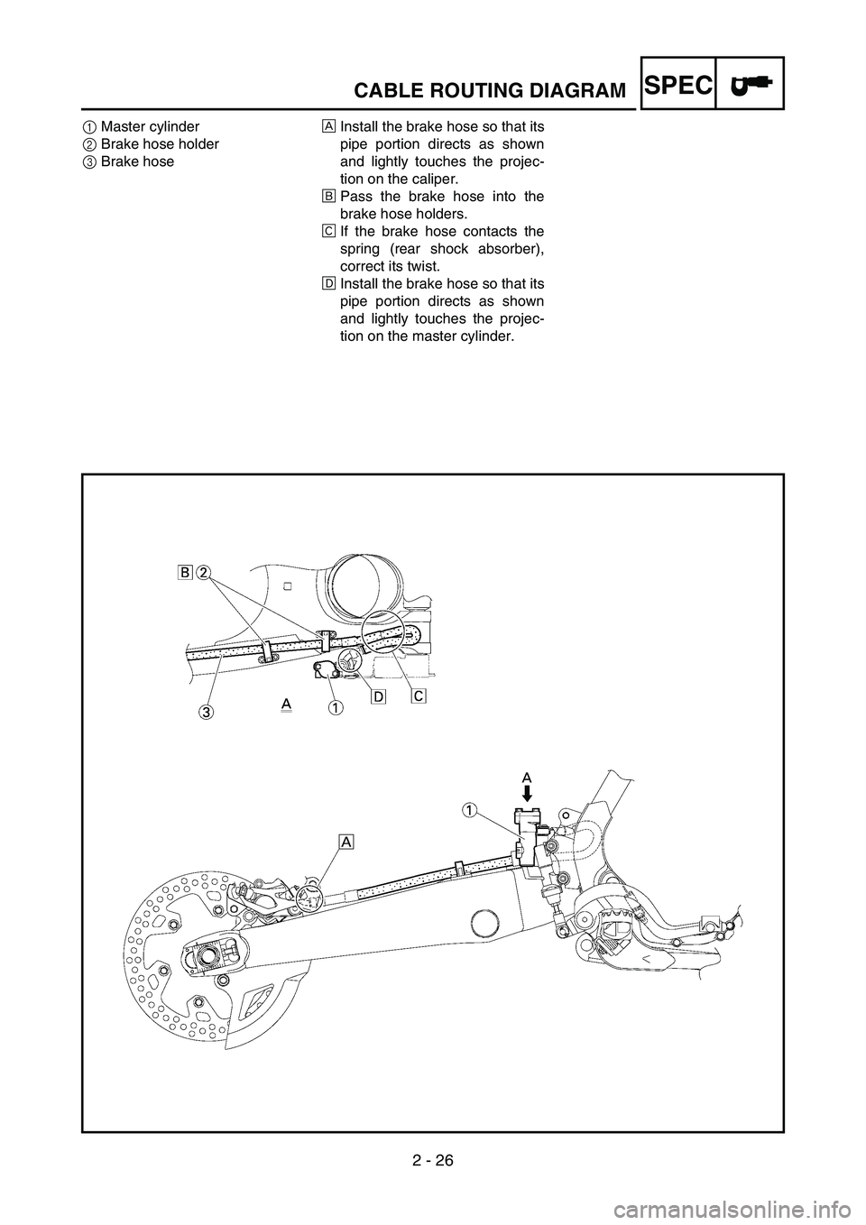
1Master cylinder
2Brake hose holder
3Brake hoseÈInstall the brake hose so that its
pipe portion directs as shown
and lightly touches the projec-
tion on the caliper.
ÉPass the brake hose into the
brake hose holders.
ÊIf the brake hose contacts the
spring (rear shock absorber),
correct its twist.
ËInstall the brake hose so that its
pipe portion directs as shown
and lightly touches the projec-
tion on the master cylinder.
Page 182 of 786

2 - 27
SPECCABLE ROUTING DIAGRAM
1Starter motor lead
2Negative battery lead
3Wire harness
4Clamp
5Taillight lead
6Coolant reservoir tank breather
hose
7Coolant reservoir hose
8Positive battery lead
9Starting circuit cut-off relay
0BatteryÈPosition the starter motor lead,
negative battery lead and wire
harness in the tank damper slit.
ÉFasten the wire harness to the
frame with a plastic locking tie
and cut off the tie end.
ÊFasten the coolant reservoir
tank breather hose and coolant
reservoir hose to the frame with
a plastic locking tie.
ËDo not allow the taillight lead to
slacken.
ÌPass the starter motor lead and
negative battery lead over the
carburetor.
ÍFasten the coolant reservoir
tank breather hose and coolant
reservoir hose to the frame with
a plastic band.ÎPass the coolant reservoir hose
on the outside of the coolant
reservoir tank breather hose.
7Ì4
Í
5
Ë
4
Ê
7
6
È3
2
1
4
É
4
Í4
Í
Î 0
968
213
Zero ~ 10 mm
(Zero ~ 0.39 in)
Page 222 of 786

3 - 14
INSP
ADJ
ENGINE OIL LEVEL INSPECTION
ENGINE OIL LEVEL INSPECTION
1. Stand the machine on a level surface.
NOTE:
When checking the oil level make sure that
the machine is upright.
Place the machine on a suitable stand.
WARNING
Never remove the oil tank cap just after
high speed operation. The heated oil could
spurt out. causing danger. Wait until the oil
cools down to approximately 70 °C (158 °F).
2. Idle the engine more than 3 minutes while
keeping the machine upright. Then stop the
engine and inspect the oil level.
3. Remove:
Oil tank cap 1
1
4. Inspect:
Oil level
Oil level should be between maximum a
and minimum b marks.
Oil level low → Add oil to proper level.
NOTE:
When inspecting the oil level, do not screw the
oil level gauge into the oil tank.
Insert the gauge lightly.
a
b
Page 230 of 786

3 - 18
INSP
ADJ
IDLE SPEED ADJUSTMENT
10. Install:
Oil filler plug
11. Inspect:
Engine (for oil leaks)
Oil level
Refer to “ENGINE OIL LEVEL INSPEC-
TION”.
12. Check:
Oil pressure
EC35M021
IDLE SPEED ADJUSTMENT
1. Start the engine and thoroughly warm it up.
2. Adjust:
Idle speed Checking steps:
Slightly loosen the oil gallery bolt 1.
Start the engine and keep it idling until oil
starts to seep from the oil gallery bolt. If no
oil comes out after one minute, turn the
engine off so it will not seize.
Check oil passages, oil filter and oil pump
for damage or leakage.
Start the engine after solving the prob-
lem(s) and recheck the oil pressure.
Tighten the oil gallery bolt to specification.
T R..
Oil gallery bolt:
10 Nm (1.0 m kg, 7.2 ft lb)
Adjustment steps:
Turn the throttle stop screw 1 until the
specified engine idling speed.
NOTE:
Using a digital engine tachometer for idle
speed adjustment, detect the engine idling
speed by bringing the sensing element c of
the engine tachometer close to the ignition
coil 2.
To increase idle speed
→
Turn the throttle stop screw
1 in
a.
To decrease idle speed
→
Turn the throttle stop screw
1 out
b.
Engine idling speed:
1,700 ~ 1,900 r/min
c2
Page 244 of 786

3 - 24
INSP
ADJ
SPARK ARRESTER CLEANING (For USA)
WARNING
Be sure the exhaust pipe and silencer are
cool before cleaning the spark arrester.
Do not start the engine when cleaning the
exhaust system.
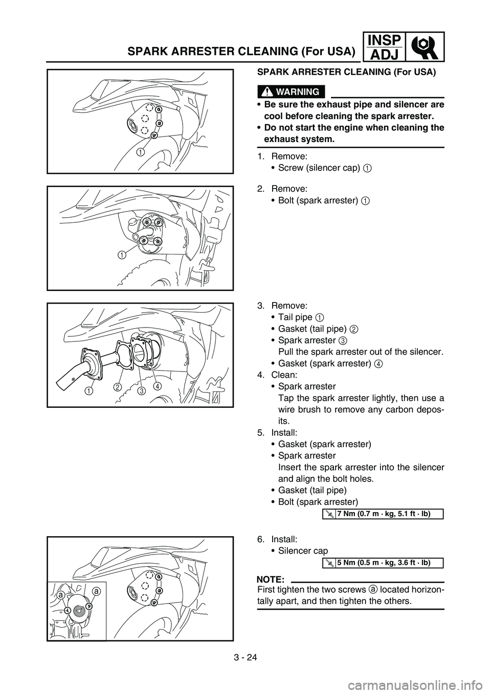
1. Remove:
Screw (silencer cap) 1
1
2. Remove:
Bolt (spark arrester) 1
1
3. Remove:
Tail pipe 1
Gasket (tail pipe) 2
Spark arrester 3
Pull the spark arrester out of the silencer.
Gasket (spark arrester) 4
4. Clean:
Spark arrester
Tap the spark arrester lightly, then use a
wire brush to remove any carbon depos-
its.
5. Install:
Gasket (spark arrester)
Spark arrester
Insert the spark arrester into the silencer
and align the bolt holes.
Gasket (tail pipe)
Bolt (spark arrester)
12
34
T R..7 Nm (0.7 m · kg, 5.1 ft · lb)
6. Install:
Silencer cap
NOTE:
First tighten the two screws a located horizon-
tally apart, and then tighten the others.aa
T R..5 Nm (0.5 m · kg, 3.6 ft · lb)
SPARK ARRESTER CLEANING (For USA)
Page 284 of 786

3 - 44
INSP
ADJ
STEERING HEAD INSPECTION AND ADJUSTMENT
2. Inspect:
Bearing free play
Exist play → Replace.
STEERING HEAD INSPECTION AND
ADJUSTMENT
1. Elevate the front wheel by placing a suit-
able stand under the engine.
2. Check:
Steering shaft
Grasp the bottom of the forks and gently
rock the fork assembly back and forth.
Free play → Adjust steering head.
3. Check:
Steering smooth action
Turn the handlebar lock to lock.
Unsmooth action → Adjust steering ring
nut.
4. Adjust:
Steering ring nut
Steering ring nut adjustment steps:
Remove the headlight.
Remove the handlebar and handle crown.
Loosen the ring nut 1 using the ring nut
wrench 2.
Ring nut wrench:
YU-33975/90890-01403
Page 286 of 786

3 - 45
INSP
ADJ
STEERING HEAD INSPECTION AND ADJUSTMENT
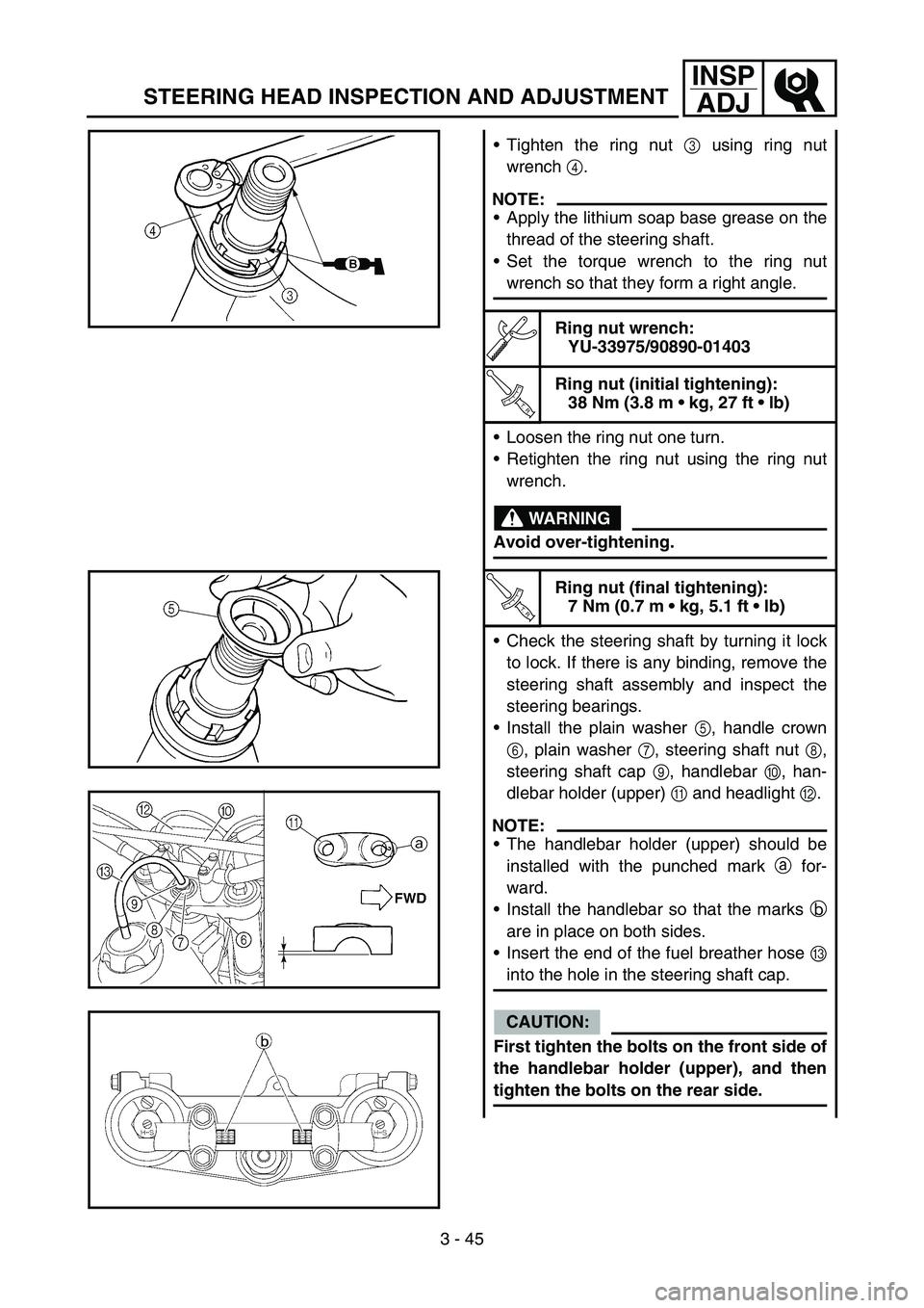
Tighten the ring nut 3 using ring nut
wrench 4.
NOTE:
Apply the lithium soap base grease on the
thread of the steering shaft.
Set the torque wrench to the ring nut
wrench so that they form a right angle.
Ring nut wrench:
YU-33975/90890-01403
T R..
Ring nut (initial tightening):
38 Nm (3.8 m kg, 27 ft lb)
Loosen the ring nut one turn.
Retighten the ring nut using the ring nut
wrench.
WARNING
Avoid over-tightening.
T R..
Ring nut (final tightening):
7 Nm (0.7 m kg, 5.1 ft lb)
Check the steering shaft by turning it lock
to lock. If there is any binding, remove the
steering shaft assembly and inspect the
steering bearings.
Install the plain washer 5, handle crown
6, plain washer 7, steering shaft nut 8,
steering shaft cap 9, handlebar 0, han-
dlebar holder (upper) A and headlight B.
NOTE:
The handlebar holder (upper) should be
installed with the punched mark a for-
ward.
Install the handlebar so that the marks b
are in place on both sides.
Insert the end of the fuel breather hose C
into the hole in the steering shaft cap.
CAUTION:
First tighten the bolts on the front side of
the handlebar holder (upper), and then
tighten the bolts on the rear side.
Page 288 of 786

3 - 46
INSP
ADJ
T R..
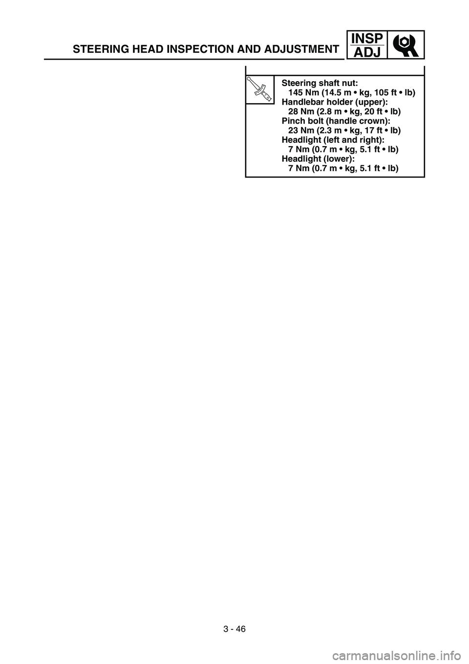
Steering shaft nut:
145 Nm (14.5 m kg, 105 ft lb)
Handlebar holder (upper):
28 Nm (2.8 m kg, 20 ft lb)
Pinch bolt (handle crown):
23 Nm (2.3 m kg, 17 ft lb)
Headlight (left and right):
7 Nm (0.7 m kg, 5.1 ft lb)
Headlight (lower):
7 Nm (0.7 m kg, 5.1 ft lb)
STEERING HEAD INSPECTION AND ADJUSTMENT