check engine YAMAHA WR 450F 2008 Owners Manual
[x] Cancel search | Manufacturer: YAMAHA, Model Year: 2008, Model line: WR 450F, Model: YAMAHA WR 450F 2008Pages: 224, PDF Size: 13.7 MB
Page 6 of 224
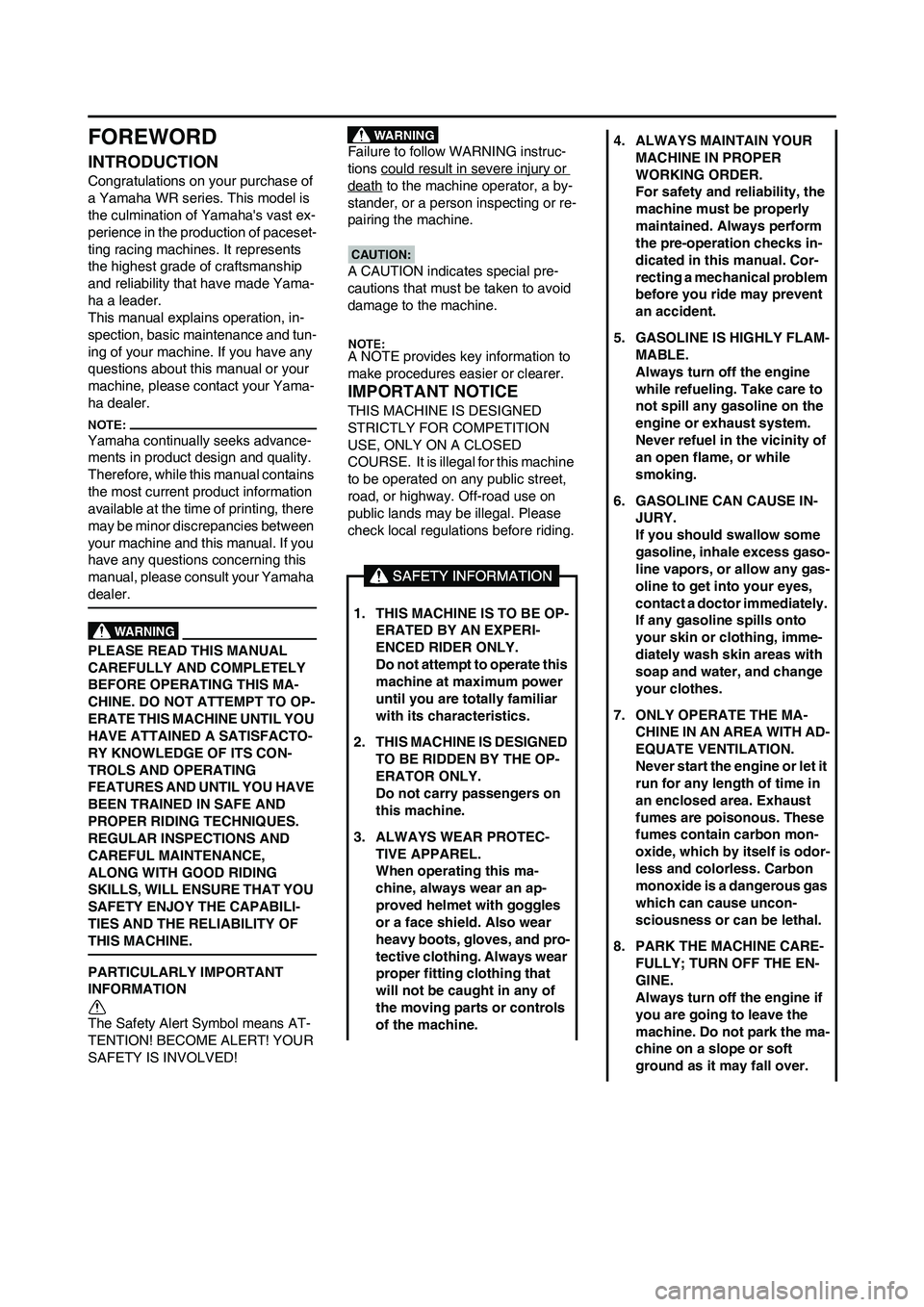
FOREWORD
INTRODUCTION
Congratulations on your purchase of
a Yamaha WR series. This model is
the culmination of Yamaha's vast ex-
perience in the production of paceset-
ting racing machines. It represents
the highest grade of craftsmanship
and reliability that have made Yama-
ha a leader.
This manual explains operation, in-
spection, basic maintenance and tun-
ing of your machine. If you have any
questions about this manual or your
machine, please contact your Yama-
ha dealer.
Yamaha continually seeks advance-
ments in product design and quality.
Therefore, while this manual contains
the most current product information
available at the time of printing, there
may be minor discrepancies between
your machine and this manual. If you
have any questions concerning this
manual, please consult your Yamaha
dealer.
PLEASE READ THIS MANUAL
CAREFULLY AND COMPLETELY
BEFORE OPERATING THIS MA-
CHINE. DO NOT ATTEMPT TO OP-
ERATE THIS MACHINE UNTIL YOU
HAVE ATTAINED A SATISFACTO-
RY KNOWLEDGE OF ITS CON-
TROLS AND OPERATING
FEATURES AND UNTIL YOU HAVE
BEEN TRAINED IN SAFE AND
PROPER RIDING TECHNIQUES.
REGULAR INSPECTIONS AND
CAREFUL MAINTENANCE,
ALONG WITH GOOD RIDING
SKILLS, WILL ENSURE THAT YOU
SAFETY ENJOY THE CAPABILI-
TIES AND THE RELIABILITY OF
THIS MACHINE.
PARTICULARLY IMPORTANT
INFORMATION
The Safety Alert Symbol means AT-
TENTION! BECOME ALERT! YOUR
SAFETY IS INVOLVED!Failure to follow WARNING instruc-
tions could result in severe injury or
death to the machine operator, a by-
stander, or a person inspecting or re-
pairing the machine.
A CAUTION indicates special pre-
cautions that must be taken to avoid
damage to the machine.
A NOTE provides key information to
make procedures easier or clearer.
IMPORTANT NOTICE
THIS MACHINE IS DESIGNED
STRICTLY FOR COMPETITION
USE, ONLY ON A CLOSED
COURSE. It is illegal for this machine
to be operated on any public street,
road, or highway. Off-road use on
public lands may be illegal. Please
check local regulations before riding.
1. THIS MACHINE IS TO BE OP-
ERATED BY AN EXPERI-
ENCED RIDER ONLY.
Do not attempt to operate this
machine at maximum power
until you are totally familiar
with its characteristics.
2. THIS MACHINE IS DESIGNED
TO BE RIDDEN BY THE OP-
ERATOR ONLY.
Do not carry passengers on
this machine.
3. ALWAYS WEAR PROTEC-
TIVE APPAREL.
When operating this ma-
chine, always wear an ap-
proved helmet with goggles
or a face shield. Also wear
heavy boots, gloves, and pro-
tective clothing. Always wear
proper fitting clothing that
will not be caught in any of
the moving parts or controls
of the machine.
4. ALWAYS MAINTAIN YOUR
MACHINE IN PROPER
WORKING ORDER.
For safety and reliability, the
machine must be properly
maintained. Always perform
the pre-operation checks in-
dicated in this manual. Cor-
recting a mechanical problem
before you ride may prevent
an accident.
5. GASOLINE IS HIGHLY FLAM-
MABLE.
Always turn off the engine
while refueling. Take care to
not spill any gasoline on the
engine or exhaust system.
Never refuel in the vicinity of
an open flame, or while
smoking.
6. GASOLINE CAN CAUSE IN-
JURY.
If you should swallow some
gasoline, inhale excess gaso-
line vapors, or allow any gas-
oline to get into your eyes,
contact a doctor immediately.
If any gasoline spills onto
your skin or clothing, imme-
diately wash skin areas with
soap and water, and change
your clothes.
7. ONLY OPERATE THE MA-
CHINE IN AN AREA WITH AD-
EQUATE VENTILATION.
Never start the engine or let it
run for any length of time in
an enclosed area. Exhaust
fumes are poisonous. These
fumes contain carbon mon-
oxide, which by itself is odor-
less and colorless. Carbon
monoxide is a dangerous gas
which can cause uncon-
sciousness or can be lethal.
8. PARK THE MACHINE CARE-
FULLY; TURN OFF THE EN-
GINE.
Always turn off the engine if
you are going to leave the
machine. Do not park the ma-
chine on a slope or soft
ground as it may fall over.
Page 10 of 224
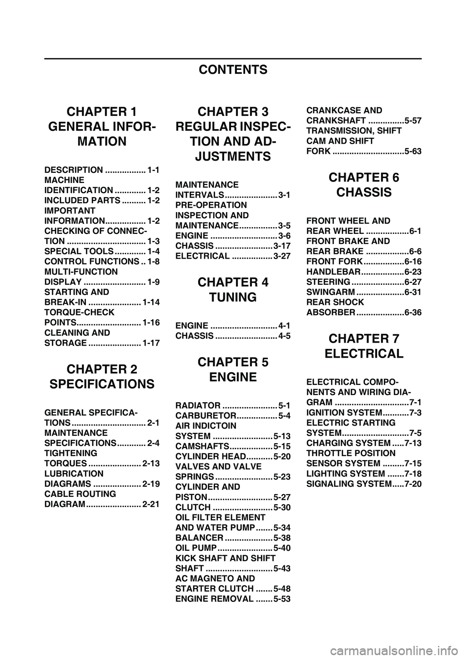
CONTENTS
CHAPTER 1
GENERAL INFOR-
MATION
DESCRIPTION ................. 1-1
MACHINE
IDENTIFICATION ............. 1-2
INCLUDED PARTS .......... 1-2
IMPORTANT
INFORMATION................. 1-2
CHECKING OF CONNEC-
TION ................................. 1-3
SPECIAL TOOLS ............. 1-4
CONTROL FUNCTIONS .. 1-8
MULTI-FUNCTION
DISPLAY .......................... 1-9
STARTING AND
BREAK-IN ...................... 1-14
TORQUE-CHECK
POINTS........................... 1-16
CLEANING AND
STORAGE ...................... 1-17
CHAPTER 2
SPECIFICATIONS
GENERAL SPECIFICA-
TIONS ............................... 2-1
MAINTENANCE
SPECIFICATIONS ............ 2-4
TIGHTENING
TORQUES ...................... 2-13
LUBRICATION
DIAGRAMS .................... 2-19
CABLE ROUTING
DIAGRAM ....................... 2-21
CHAPTER 3
REGULAR INSPEC-
TION AND AD-
JUSTMENTS
MAINTENANCE
INTERVALS ...................... 3-1
PRE-OPERATION
INSPECTION AND
MAINTENANCE................ 3-5
ENGINE ............................ 3-6
CHASSIS ........................ 3-17
ELECTRICAL ................. 3-27
CHAPTER 4
TUNING
ENGINE ............................ 4-1
CHASSIS .......................... 4-5
CHAPTER 5
ENGINE
RADIATOR ....................... 5-1
CARBURETOR................. 5-4
AIR INDICTOIN
SYSTEM ......................... 5-13
CAMSHAFTS.................. 5-15
CYLINDER HEAD........... 5-20
VALVES AND VALVE
SPRINGS ........................ 5-23
CYLINDER AND
PISTON ........................... 5-27
CLUTCH ......................... 5-30
OIL FILTER ELEMENT
AND WATER PUMP ....... 5-34
BALANCER .................... 5-38
OIL PUMP ....................... 5-40
KICK SHAFT AND SHIFT
SHAFT ............................ 5-43
AC MAGNETO AND
STARTER CLUTCH ....... 5-48
ENGINE REMOVAL ....... 5-53CRANKCASE AND
CRANKSHAFT ...............5-57
TRANSMISSION, SHIFT
CAM AND SHIFT
FORK ..............................5-63
CHAPTER 6
CHASSIS
FRONT WHEEL AND
REAR WHEEL ..................6-1
FRONT BRAKE AND
REAR BRAKE ..................6-6
FRONT FORK .................6-16
HANDLEBAR..................6-23
STEERING ......................6-27
SWINGARM ....................6-31
REAR SHOCK
ABSORBER ....................6-36
CHAPTER 7
ELECTRICAL
ELECTRICAL COMPO-
NENTS AND WIRING DIA-
GRAM ...............................7-1
IGNITION SYSTEM...........7-3
ELECTRIC STARTING
SYSTEM............................7-5
CHARGING SYSTEM .....7-13
THROTTLE POSITION
SENSOR SYSTEM .........7-15
LIGHTING SYSTEM .......7-18
SIGNALING SYSTEM.....7-20
Page 24 of 224
1-14
STARTING AND BREAK-IN
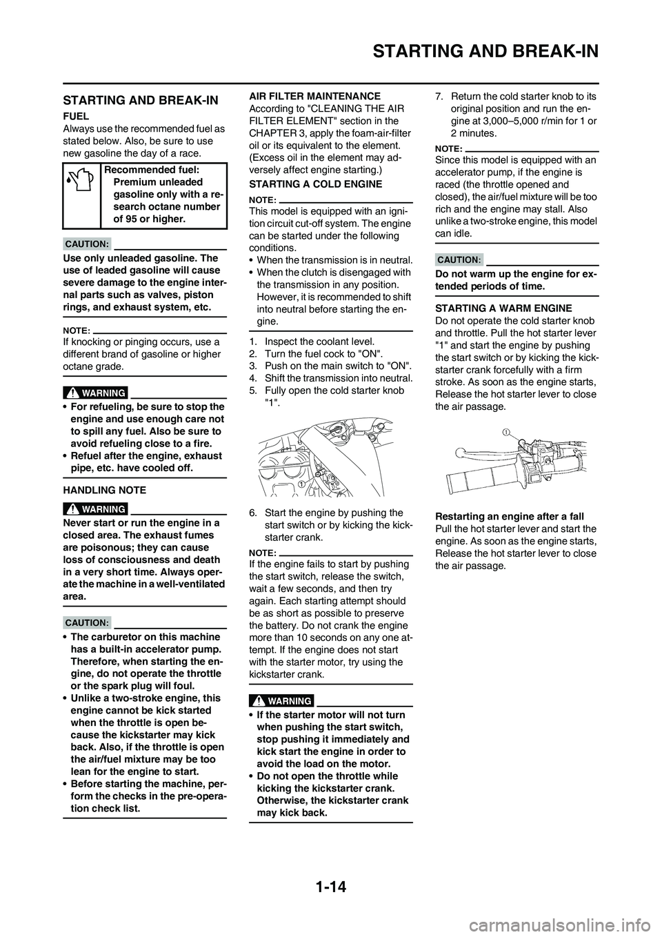
STARTING AND BREAK-IN
FUEL
Always use the recommended fuel as
stated below. Also, be sure to use
new gasoline the day of a race.
Use only unleaded gasoline. The
use of leaded gasoline will cause
severe damage to the engine inter-
nal parts such as valves, piston
rings, and exhaust system, etc.
If knocking or pinging occurs, use a
different brand of gasoline or higher
octane grade.
• For refueling, be sure to stop the
engine and use enough care not
to spill any fuel. Also be sure to
avoid refueling close to a fire.
• Refuel after the engine, exhaust
pipe, etc. have cooled off.
HANDLING NOTE
Never start or run the engine in a
closed area. The exhaust fumes
are poisonous; they can cause
loss of consciousness and death
in a very short time. Always oper-
ate the machine in a well-ventilated
area.
• The carburetor on this machine
has a built-in accelerator pump.
Therefore, when starting the en-
gine, do not operate the throttle
or the spark plug will foul.
• Unlike a two-stroke engine, this
engine cannot be kick started
when the throttle is open be-
cause the kickstarter may kick
back. Also, if the throttle is open
the air/fuel mixture may be too
lean for the engine to start.
• Before starting the machine, per-
form the checks in the pre-opera-
tion check list.
AIR FILTER MAINTENANCE
According to "CLEANING THE AIR
FILTER ELEMENT" section in the
CHAPTER 3, apply the foam-air-filter
oil or its equivalent to the element.
(Excess oil in the element may ad-
versely affect engine starting.)
STARTING A COLD ENGINE
This model is equipped with an igni-
tion circuit cut-off system. The engine
can be started under the following
conditions.
• When the transmission is in neutral.
• When the clutch is disengaged with
the transmission in any position.
However, it is recommended to shift
into neutral before starting the en-
gine.
1. Inspect the coolant level.
2. Turn the fuel cock to "ON".
3. Push on the main switch to "ON".
4. Shift the transmission into neutral.
5. Fully open the cold starter knob
"1".
6. Start the engine by pushing the
start switch or by kicking the kick-
starter crank.
If the engine fails to start by pushing
the start switch, release the switch,
wait a few seconds, and then try
again. Each starting attempt should
be as short as possible to preserve
the battery. Do not crank the engine
more than 10 seconds on any one at-
tempt. If the engine does not start
with the starter motor, try using the
kickstarter crank.
• If the starter motor will not turn
when pushing the start switch,
stop pushing it immediately and
kick start the engine in order to
avoid the load on the motor.
• Do not open the throttle while
kicking the kickstarter crank.
Otherwise, the kickstarter crank
may kick back.
7. Return the cold starter knob to its
original position and run the en-
gine at 3,000–5,000 r/min for 1 or
2 minutes.
Since this model is equipped with an
accelerator pump, if the engine is
raced (the throttle opened and
closed), the air/fuel mixture will be too
rich and the engine may stall. Also
unlike a two-stroke engine, this model
can idle.
Do not warm up the engine for ex-
tended periods of time.
STARTING A WARM ENGINE
Do not operate the cold starter knob
and throttle. Pull the hot starter lever
"1" and start the engine by pushing
the start switch or by kicking the kick-
starter crank forcefully with a firm
stroke. As soon as the engine starts,
Release the hot starter lever to close
the air passage.
Restarting an engine after a fall
Pull the hot starter lever and start the
engine. As soon as the engine starts,
Release the hot starter lever to close
the air passage. Recommended fuel:
Premium unleaded
gasoline only with a re-
search octane number
of 95 or higher.
Page 25 of 224

1-15
STARTING AND BREAK-IN
The engine fails to start
Pull the hot starter lever all the way
out and while holding the lever, kick
the kickstarter crank 10 to 20 times to
clear the engine. Then, restart the en-
gine. Refer to "Restarting an engine
after a fall".
Observe the following break-in
procedures during initial operation
to ensure optimum performance
and avoid engine damage.
BREAK-IN PROCEDURES
1. Before starting the engine, fill the
fuel tank with the fuel.
2. Perform the pre-operation checks
on the machine.
3. Start and warm up the engine.
Check the idle speed, and check
the operation of the controls and
the engine stop switch. Then, re-
start the engine and check its op-
eration within no more than 5
minutes after it is restarted.4. Operate the machine in the lower
gears at moderate throttle open-
ings for five to eight minutes.
5. Check how the engine runs when
the machine is ridden with the
throttle 1/4 to 1/2 open (low to me-
dium speed) for about one hour.
6. Restart the engine and check the
operation of the machine through-
out its entire operating range. Re-
start the machine and operate it
for about 10 to 15 more minutes.
The machine will now be ready to
race.
• After the break-in or before each
race, you must check the entire
machine for loose fittings and
fasteners as per "TORQUE-
CHECK POINTS". Tighten all
such fasteners as required.
• When any of the following parts
have been replaced, they must
be broken in.
CYLINDER AND CRANKSHAFT:
About one hour of break-in oper-
ation is necessary.
PISTON, RING, VALVES, CAM-
SHAFTS AND GEARS:
These parts require about 30
minutes of break-in operation at
half-throttle or less. Observe the
condition of the engine carefully
during operation.
Thro
ttle
grip
op-
era-
tion*Cold
start-
er
knobHot
start-
er le-
ver
St
ar
ti
n
g
a
c
ol
d
e
n
gi
n
eAir tempera-
ture = less
than 5 °C (41
°F)Ope
n 3
or 4
time
sON OFF
Air tempera-
ture = more
than 5 °C (41
°F)Non
eON OFF
Air tempera-
ture (normal
temperature)
= between 5
°C (41 °F)
and 25 °C
(77 °F)Non
eON/
OFFOFF
Air tempera-
ture = more
than 25 °C
(77 °F)Non
eOFF OFF
Starting an en-
gine after a long
period of timeNon
eON OFF
Restarting a
warm engineNon
eOFF ON
Restarting an en-
gine after a fallNon
eOFF ON
* Operate the throttle grip before kick
starting.
Page 26 of 224
1-16
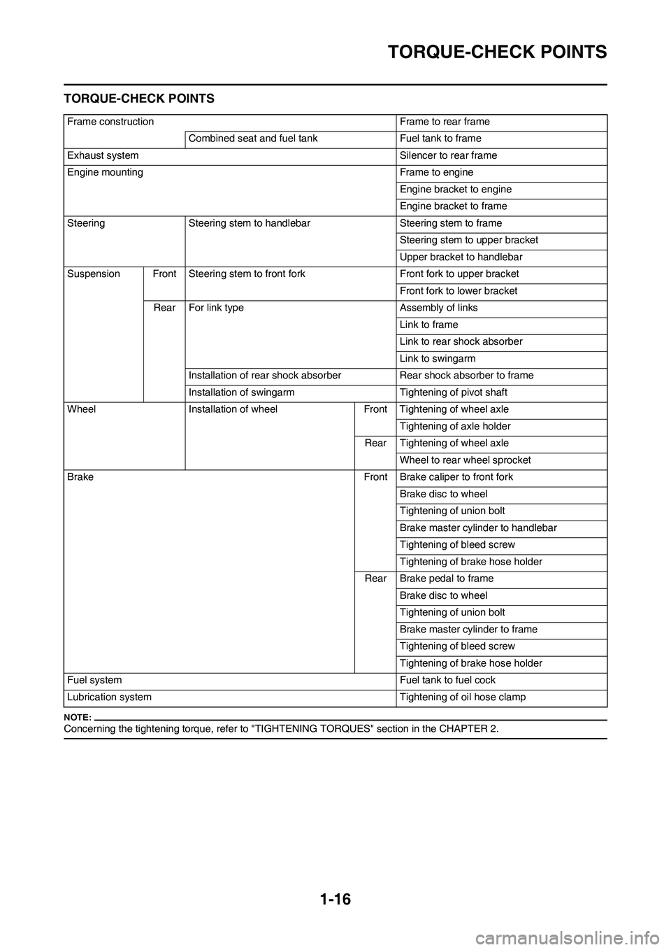
TORQUE-CHECK POINTS
TORQUE-CHECK POINTS
Concerning the tightening torque, refer to "TIGHTENING TORQUES" section in the CHAPTER 2.
Frame construction Frame to rear frame
Combined seat and fuel tank Fuel tank to frame
Exhaust system Silencer to rear frame
Engine mounting Frame to engine
Engine bracket to engine
Engine bracket to frame
Steering Steering stem to handlebar Steering stem to frame
Steering stem to upper bracket
Upper bracket to handlebar
Suspension Front Steering stem to front fork Front fork to upper bracket
Front fork to lower bracket
Rear For link type Assembly of links
Link to frame
Link to rear shock absorber
Link to swingarm
Installation of rear shock absorber Rear shock absorber to frame
Installation of swingarm Tightening of pivot shaft
Wheel Installation of wheel Front Tightening of wheel axle
Tightening of axle holder
Rear Tightening of wheel axle
Wheel to rear wheel sprocket
Brake Front Brake caliper to front fork
Brake disc to wheel
Tightening of union bolt
Brake master cylinder to handlebar
Tightening of bleed screw
Tightening of brake hose holder
Rear Brake pedal to frame
Brake disc to wheel
Tightening of union bolt
Brake master cylinder to frame
Tightening of bleed screw
Tightening of brake hose holder
Fuel system Fuel tank to fuel cock
Lubrication system Tightening of oil hose clamp
Page 40 of 224
2-13
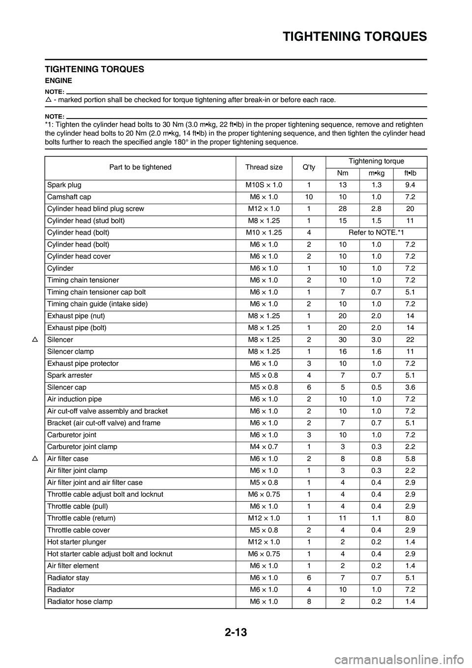
TIGHTENING TORQUES
TIGHTENING TORQUES
ENGINE
△- marked portion shall be checked for torque tightening after break-in or before each race.
*1: Tighten the cylinder head bolts to 30 Nm (3.0 m•kg, 22 ft•lb) in the proper tightening sequence, remove and retighten
the cylinder head bolts to 20 Nm (2.0 m•kg, 14 ft•lb) in the proper tightening sequence, and then tighten the cylinder head
bolts further to reach the specified angle 180° in the proper tightening sequence.
Part to be tightened Thread size Q'tyTightening torque
Nm m•kg ft•lb
Spark plug M10S × 1.0 1 13 1.3 9.4
Camshaft cap M6 × 1.0 10 10 1.0 7.2
Cylinder head blind plug screw M12 × 1.0 1 28 2.8 20
Cylinder head (stud bolt) M8 × 1.25 1 15 1.5 11
Cylinder head (bolt) M10 × 1.25 4 Refer to NOTE.*1
Cylinder head (bolt) M6 × 1.0 2 10 1.0 7.2
Cylinder head cover M6 × 1.0 2 10 1.0 7.2
Cylinder M6 × 1.0 1 10 1.0 7.2
Timing chain tensioner M6 × 1.0 2 10 1.0 7.2
Timing chain tensioner cap bolt M6 × 1.0 1 7 0.7 5.1
Timing chain guide (intake side) M6 × 1.0 2 10 1.0 7.2
Exhaust pipe (nut) M8 × 1.25 1 20 2.0 14
Exhaust pipe (bolt) M8 × 1.25 1 20 2.0 14
△Silencer M8 × 1.25 2 30 3.0 22
Silencer clamp M8 × 1.25 1 16 1.6 11
Exhaust pipe protector M6 × 1.0 3 10 1.0 7.2
Spark arrester M5 × 0.8 4 7 0.7 5.1
Silencer cap M5 × 0.8 6 5 0.5 3.6
Air induction pipe M6 × 1.0 2 10 1.0 7.2
Air cut-off valve assembly and bracket M6 × 1.0 2 10 1.0 7.2
Bracket (air cut-off valve) and frame M6 × 1.0 2 7 0.7 5.1
Carburetor joint M6 × 1.0 3 10 1.0 7.2
Carburetor joint clamp M4 × 0.7 1 3 0.3 2.2
△Air filter case M6 × 1.0 2 8 0.8 5.8
Air filter joint clamp M6 × 1.0 1 3 0.3 2.2
Air filter joint and air filter case M5 × 0.8 1 4 0.4 2.9
Throttle cable adjust bolt and locknut M6 × 0.75 1 4 0.4 2.9
Throttle cable (pull) M6 × 1.0 1 4 0.4 2.9
Throttle cable (return) M12 × 1.0 1 11 1.1 8.0
Throttle cable cover M5 × 0.8 2 4 0.4 2.9
Hot starter plunger M12 × 1.0 1 2 0.2 1.4
Hot starter cable adjust bolt and locknut M6 × 0.75 1 4 0.4 2.9
Air filter element M6 × 1.0 1 2 0.2 1.4
Radiator stay M6 × 1.0 6 7 0.7 5.1
Radiator M6 × 1.0 4 10 1.0 7.2
Radiator hose clamp M6 × 1.0 8 2 0.2 1.4
Page 41 of 224
2-14
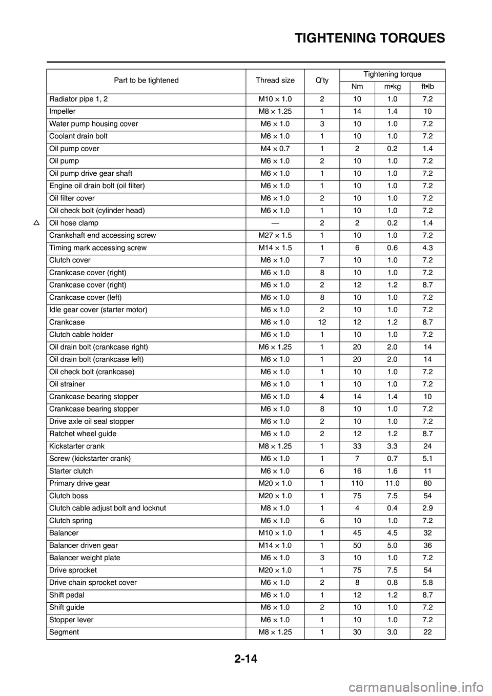
TIGHTENING TORQUES
Radiator pipe 1, 2 M10 × 1.0 2 10 1.0 7.2
Impeller M8 × 1.25 1 14 1.4 10
Water pump housing cover M6 × 1.0 3 10 1.0 7.2
Coolant drain bolt M6 × 1.0 1 10 1.0 7.2
Oil pump cover M4 × 0.7 1 2 0.2 1.4
Oil pump M6 × 1.0 2 10 1.0 7.2
Oil pump drive gear shaft M6 × 1.0 1 10 1.0 7.2
Engine oil drain bolt (oil filter) M6 × 1.0 1 10 1.0 7.2
Oil filter cover M6 × 1.0 2 10 1.0 7.2
Oil check bolt (cylinder head) M6 × 1.0 1 10 1.0 7.2
△Oil hose clamp — 2 2 0.2 1.4
Crankshaft end accessing screw M27 × 1.5 1 10 1.0 7.2
Timing mark accessing screw M14 × 1.5 1 6 0.6 4.3
Clutch cover M6 × 1.0 7 10 1.0 7.2
Crankcase cover (right) M6 × 1.0 8 10 1.0 7.2
Crankcase cover (right) M6 × 1.0 2 12 1.2 8.7
Crankcase cover (left) M6 × 1.0 8 10 1.0 7.2
Idle gear cover (starter motor) M6 × 1.0 2 10 1.0 7.2
Crankcase M6 × 1.0 12 12 1.2 8.7
Clutch cable holder M6 × 1.0 1 10 1.0 7.2
Oil drain bolt (crankcase right) M6 × 1.25 1 20 2.0 14
Oil drain bolt (crankcase left) M6 × 1.0 1 20 2.0 14
Oil check bolt (crankcase) M6 × 1.0 1 10 1.0 7.2
Oil strainer M6 × 1.0 1 10 1.0 7.2
Crankcase bearing stopper M6 × 1.0 4 14 1.4 10
Crankcase bearing stopper M6 × 1.0 8 10 1.0 7.2
Drive axle oil seal stopper M6 × 1.0 2 10 1.0 7.2
Ratchet wheel guide M6 × 1.0 2 12 1.2 8.7
Kickstarter crank M8 × 1.25 1 33 3.3 24
Screw (kickstarter crank) M6 × 1.0 1 7 0.7 5.1
Starter clutch M6 × 1.0 6 16 1.6 11
Primary drive gear M20 × 1.0 1 110 11.0 80
Clutch boss M20 × 1.0 1 75 7.5 54
Clutch cable adjust bolt and locknut M8 × 1.0 1 4 0.4 2.9
Clutch spring M6 × 1.0 6 10 1.0 7.2
Balancer M10 × 1.0 1 45 4.5 32
Balancer driven gear M14 × 1.0 1 50 5.0 36
Balancer weight plate M6 × 1.0 3 10 1.0 7.2
Drive sprocket M20 × 1.0 1 75 7.5 54
Drive chain sprocket cover M6 × 1.0 2 8 0.8 5.8
Shift pedal M6 × 1.0 1 12 1.2 8.7
Shift guide M6 × 1.0 2 10 1.0 7.2
Stopper lever M6 × 1.0 1 10 1.0 7.2
Segment M8 × 1.25 1 30 3.0 22Part to be tightened Thread size Q'tyTightening torque
Nm m•kg ft•lb
Page 56 of 224
3-1
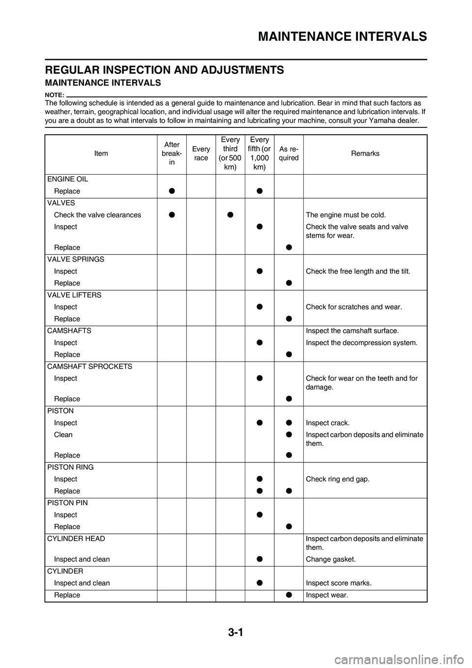
MAINTENANCE INTERVALS
REGULAR INSPECTION AND ADJUSTMENTS
MAINTENANCE INTERVALS
The following schedule is intended as a general guide to maintenance and lubrication. Bear in mind that such factors as
weather, terrain, geographical location, and individual usage will alter the required maintenance and lubrication intervals. If
you are a doubt as to what intervals to follow in maintaining and lubricating your machine, consult your Yamaha dealer.
ItemAfter
break-
inEvery
race
Every
third
(or 500
km)Every
fifth (or
1,000
km)
As re-
quiredRemarks
ENGINE OIL
Replace●●
VALVES
Check the valve clearances●●The engine must be cold.
Inspect●Check the valve seats and valve
stems for wear.
Replace●
VALVE SPRINGS
Inspect●Check the free length and the tilt.
Replace●
VALVE LIFTERS
Inspect●Check for scratches and wear.
Replace●
CAMSHAFTS Inspect the camshaft surface.
Inspect●Inspect the decompression system.
Replace●
CAMSHAFT SPROCKETS
Inspect●Check for wear on the teeth and for
damage.
Replace●
PISTON
Inspect●●Inspect crack.
Clean●Inspect carbon deposits and eliminate
them.
Replace●
PISTON RING
Inspect●Check ring end gap.
Replace●●
PISTON PIN
Inspect●
Replace●
CYLINDER HEAD Inspect carbon deposits and eliminate
them.
Inspect and clean●Change gasket.
CYLINDER
Inspect and clean●Inspect score marks.
Replace●Inspect wear.
Page 60 of 224
3-5
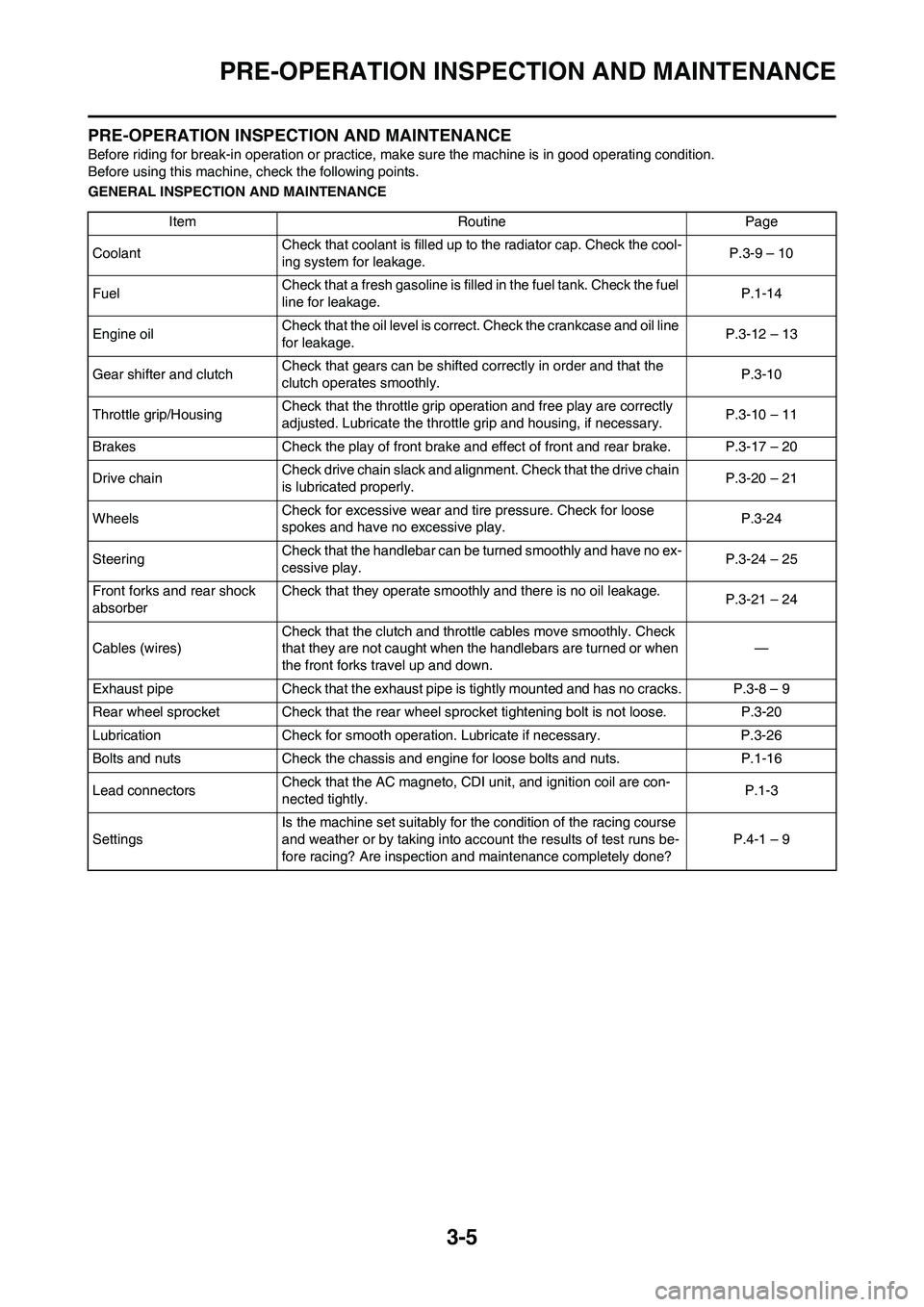
PRE-OPERATION INSPECTION AND MAINTENANCE
PRE-OPERATION INSPECTION AND MAINTENANCE
Before riding for break-in operation or practice, make sure the machine is in good operating condition.
Before using this machine, check the following points.
GENERAL INSPECTION AND MAINTENANCE
Item Routine Page
CoolantCheck that coolant is filled up to the radiator cap. Check the cool-
ing system for leakage.P.3-9 – 10
FuelCheck that a fresh gasoline is filled in the fuel tank. Check the fuel
line for leakage.P.1-14
Engine oilCheck that the oil level is correct. Check the crankcase and oil line
for leakage.P.3-12 – 13
Gear shifter and clutchCheck that gears can be shifted correctly in order and that the
clutch operates smoothly.P.3-10
Throttle grip/HousingCheck that the throttle grip operation and free play are correctly
adjusted. Lubricate the throttle grip and housing, if necessary.P.3-10 – 11
Brakes Check the play of front brake and effect of front and rear brake. P.3-17 – 20
Drive chainCheck drive chain slack and alignment. Check that the drive chain
is lubricated properly.P.3-20 – 21
WheelsCheck for excessive wear and tire pressure. Check for loose
spokes and have no excessive play.P.3-24
SteeringCheck that the handlebar can be turned smoothly and have no ex-
cessive play.P.3-24 – 25
Front forks and rear shock
absorberCheck that they operate smoothly and there is no oil leakage.
P.3-21 – 24
Cables (wires)Check that the clutch and throttle cables move smoothly. Check
that they are not caught when the handlebars are turned or when
the front forks travel up and down.—
Exhaust pipe Check that the exhaust pipe is tightly mounted and has no cracks. P.3-8 – 9
Rear wheel sprocket Check that the rear wheel sprocket tightening bolt is not loose. P.3-20
Lubrication Check for smooth operation. Lubricate if necessary. P.3-26
Bolts and nuts Check the chassis and engine for loose bolts and nuts. P.1-16
Lead connectorsCheck that the AC magneto, CDI unit, and ignition coil are con-
nected tightly.P.1-3
SettingsIs the machine set suitably for the condition of the racing course
and weather or by taking into account the results of test runs be-
fore racing? Are inspection and maintenance completely done?P.4-1 – 9
Page 64 of 224
3-9
ENGINE
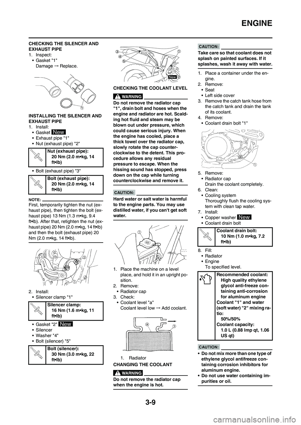
CHECKING THE SILENCER AND
EXHAUST PIPE
1. Inspect:
• Gasket "1"
Damage→Replace.
INSTALLING THE SILENCER AND
EXHAUST PIPE
1. Install:
• Gasket
• Exhaust pipe "1"
• Nut (exhaust pipe) "2"
• Bolt (exhaust pipe) "3"
First, temporarily tighten the nut (ex-
haust pipe), then tighten the bolt (ex-
haust pipe) 13 Nm (1.3 m•kg, 9.4
ft•lb). After that, retighten the nut (ex-
haust pipe) 20 Nm (2.0 m•kg, 14 ft•lb)
and then the bolt (exhaust pipe) 20
Nm (2.0 m•kg, 14 ft•lb).
2. Install:
• Silencer clamp "1"
• Gasket "2"
• Silencer
• Washer "4"
• Bolt (silencer) "5"CHECKING THE COOLANT LEVEL
Do not remove the radiator cap
"1", drain bolt and hoses when the
engine and radiator are hot. Scald-
ing hot fluid and steam may be
blown out under pressure, which
could cause serious injury. When
the engine has cooled, place a
thick towel over the radiator cap,
slowly rotate the cap counter-
clockwise to the detent. This pro-
cedure allows any residual
pressure to escape. When the
hissing sound has stopped, press
down on the cap while turning
counterclockwise and remove it.
Hard water or salt water is harmful
to the engine parts. You may use
distilled water, if you can't get soft
water.
1. Place the machine on a level
place, and hold it in an upright po-
sition.
2. Remove:
• Radiator cap
3. Check:
• Coolant level "a"
Coolant level low→Add coolant.
1. Radiator
CHANGING THE COOLANT
Do not remove the radiator cap
when the engine is hot.
Take care so that coolant does not
splash on painted surfaces. If it
splashes, wash it away with water.
1. Place a container under the en-
gine.
2. Remove:
• Seat
• Left side cover
3. Remove the catch tank hose from
the catch tank and drain the tank
of its coolant.
4. Remove:
• Coolant drain bolt "1"
5. Remove:
• Radiator cap
Drain the coolant completely.
6. Clean:
• Cooling system
Thoroughly flush the cooling sys-
tem with clean tap water.
7. Install:
• Copper washer
• Coolant drain bolt
8. Fill:
•Radiator
• Engine
To specified level.
• Do not mix more than one type of
ethylene glycol antifreeze con-
taining corrosion inhibitors for
aluminum engine.
• Do not use water containing im-
purities or oil.
Nut (exhaust pipe):
20 Nm (2.0 m•kg, 14
ft•lb)
Bolt (exhaust pipe):
20 Nm (2.0 m•kg, 14
ft•lb)
Silencer clamp:
16 Nm (1.6 m•kg, 11
ft•lb)
Bolt (silencer):
30 Nm (3.0 m•kg, 22
ft•lb)
Coolant drain bolt:
10 Nm (1.0 m•kg, 7.2
ft•lb)
Recommended coolant:
High quality ethylene
glycol anti-freeze con-
taining anti-corrosion
for aluminum engine
Coolant "1" and water
(soft water) "2" mixing ra-
tio:
50%/50%
Coolant capacity:
1.0 L (0.88 Imp qt, 1.06
US qt)