engine oil YAMAHA WR 450F 2008 Owners Manual
[x] Cancel search | Manufacturer: YAMAHA, Model Year: 2008, Model line: WR 450F, Model: YAMAHA WR 450F 2008Pages: 224, PDF Size: 13.7 MB
Page 7 of 224
TO THE NEW OWNER
This manual will provide you with a
good basic understanding of fea-
tures, operation, and basic mainte-
nance and inspection items of this
machine. Please read this manual
carefully and completely before oper-
ating your new machine. If you have
any questions regarding the opera-
tion or maintenance of your machine,
please consult your Yamaha dealer.
This manual should be considered a
permanent part of this machine and
should remain with it even if the ma-
chine is subsequently sold.
NOTICE
Some data in this manual may be-
come outdated due to improve-
ments made to this model in the
future. If there is any question you
have regarding this manual or your
machine, please consult your
Yamaha dealer.
F.I.M. MACHINE WEIGHTS
Weights of machines without fuel
The minimum weights for motocross
machines are:
for the class 125 cc:
minimum 88 kg (194 lb)
for the class 250 cc:
minimum 98 kg (216 lb)
for the class 500 cc:
minimum 102 kg (225 lb)
In modifying your machine (e.g., for
weight reduction), take note of the
above limits of weight.
HOW TO USE THIS MANUAL
FINDING THE REQUIRED PAGE
1. This manual consists of seven
chapters; "General Information",
"Specifications", "Regular inspec-
tion and adjustments", "Tuning",
"Engine", "Chassis" and "Electri-
cal".
2. The table of contents is at the be-
ginning of the manual. Look over
the general layout of the book be-
fore finding then required chapter
and item.
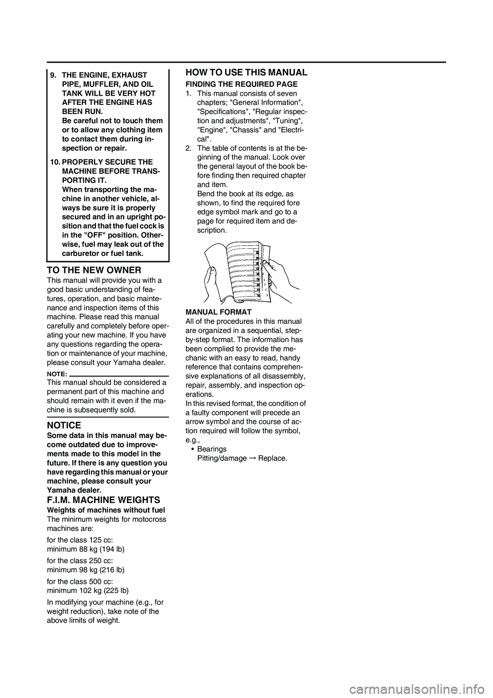
Bend the book at its edge, as
shown, to find the required fore
edge symbol mark and go to a
page for required item and de-
scription.
MANUAL FORMAT
All of the procedures in this manual
are organized in a sequential, step-
by-step format. The information has
been complied to provide the me-
chanic with an easy to read, handy
reference that contains comprehen-
sive explanations of all disassembly,
repair, assembly, and inspection op-
erations.
In this revised format, the condition of
a faulty component will precede an
arrow symbol and the course of ac-
tion required will follow the symbol,
e.g.,
•Bearings
Pitting/damage→Replace. 9. THE ENGINE, EXHAUST
PIPE, MUFFLER, AND OIL
TANK WILL BE VERY HOT
AFTER THE ENGINE HAS
BEEN RUN.
Be careful not to touch them
or to allow any clothing item
to contact them during in-
spection or repair.
10. PROPERLY SECURE THE
MACHINE BEFORE TRANS-
PORTING IT.
When transporting the ma-
chine in another vehicle, al-
ways be sure it is properly
secured and in an upright po-
sition and that the fuel cock is
in the "OFF" position. Other-
wise, fuel may leak out of the
carburetor or fuel tank.
Page 8 of 224
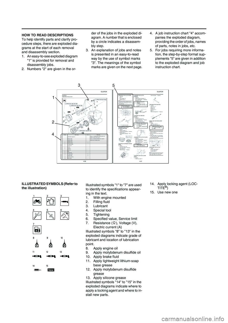
HOW TO READ DESCRIPTIONS
To help identify parts and clarify pro-
cedure steps, there are exploded dia-
grams at the start of each removal
and disassembly section.
1. An easy-to-see exploded diagram
"1" is provided for removal and
disassembly jobs.
2. Numbers "2" are given in the or-der of the jobs in the exploded di-
agram. A number that is enclosed
by a circle indicates a disassem-
bly step.
3. An explanation of jobs and notes
is presented in an easy-to-read
way by the use of symbol marks
"3". The meanings of the symbol
marks are given on the next page.4. A job instruction chart "4" accom-
panies the exploded diagram,
providing the order of jobs, names
of parts, notes in jobs, etc.
5. For jobs requiring more informa-
tion, the step-by-step format sup-
plements "5" are given in addition
to the exploded diagram and job
instruction chart.
ILLUSTRATED SYMBOLS (Refer to
the illustration)Illustrated symbols "1" to "7" are used
to identify the specifications appear-
ing in the text.
1. With engine mounted
2. Filling fluid
3. Lubricant
4. Special tool
5. Tightening
6. Specified value, Service limit
7. Resistance (Ω), Voltage (V),
Electric current (A)
Illustrated symbols "8" to "13" in the
exploded diagrams indicate grade of
lubricant and location of lubrication
point.
8. Apply engine oil
9. Apply molybdenum disulfide oil
10. Apply brake fluid
11. Apply lightweight lithium-soap
base grease
12. Apply molybdenum disulfide
grease
13. Apply silicone grease
Illustrated symbols "14" to "15" in the
exploded diagrams indicate where to
apply a locking agent and where to in-
stall new parts.14. Apply locking agent (LOC-
TITE
®)
15. Use new one
1
23
45
Page 10 of 224
CONTENTS
CHAPTER 1
GENERAL INFOR-
MATION
DESCRIPTION ................. 1-1
MACHINE
IDENTIFICATION ............. 1-2
INCLUDED PARTS .......... 1-2
IMPORTANT
INFORMATION................. 1-2
CHECKING OF CONNEC-
TION ................................. 1-3
SPECIAL TOOLS ............. 1-4
CONTROL FUNCTIONS .. 1-8
MULTI-FUNCTION
DISPLAY .......................... 1-9
STARTING AND
BREAK-IN ...................... 1-14
TORQUE-CHECK
POINTS........................... 1-16
CLEANING AND
STORAGE ...................... 1-17
CHAPTER 2
SPECIFICATIONS
GENERAL SPECIFICA-
TIONS ............................... 2-1
MAINTENANCE
SPECIFICATIONS ............ 2-4
TIGHTENING
TORQUES ...................... 2-13
LUBRICATION
DIAGRAMS .................... 2-19
CABLE ROUTING
DIAGRAM ....................... 2-21
CHAPTER 3
REGULAR INSPEC-
TION AND AD-
JUSTMENTS
MAINTENANCE
INTERVALS ...................... 3-1
PRE-OPERATION
INSPECTION AND
MAINTENANCE................ 3-5
ENGINE ............................ 3-6
CHASSIS ........................ 3-17
ELECTRICAL ................. 3-27
CHAPTER 4
TUNING
ENGINE ............................ 4-1
CHASSIS .......................... 4-5
CHAPTER 5
ENGINE
RADIATOR ....................... 5-1
CARBURETOR................. 5-4
AIR INDICTOIN
SYSTEM ......................... 5-13
CAMSHAFTS.................. 5-15
CYLINDER HEAD........... 5-20
VALVES AND VALVE
SPRINGS ........................ 5-23
CYLINDER AND
PISTON ........................... 5-27
CLUTCH ......................... 5-30
OIL FILTER ELEMENT
AND WATER PUMP ....... 5-34
BALANCER .................... 5-38
OIL PUMP ....................... 5-40
KICK SHAFT AND SHIFT
SHAFT ............................ 5-43
AC MAGNETO AND
STARTER CLUTCH ....... 5-48
ENGINE REMOVAL ....... 5-53CRANKCASE AND
CRANKSHAFT ...............5-57
TRANSMISSION, SHIFT
CAM AND SHIFT
FORK ..............................5-63
CHAPTER 6
CHASSIS
FRONT WHEEL AND
REAR WHEEL ..................6-1
FRONT BRAKE AND
REAR BRAKE ..................6-6
FRONT FORK .................6-16
HANDLEBAR..................6-23
STEERING ......................6-27
SWINGARM ....................6-31
REAR SHOCK
ABSORBER ....................6-36
CHAPTER 7
ELECTRICAL
ELECTRICAL COMPO-
NENTS AND WIRING DIA-
GRAM ...............................7-1
IGNITION SYSTEM...........7-3
ELECTRIC STARTING
SYSTEM............................7-5
CHARGING SYSTEM .....7-13
THROTTLE POSITION
SENSOR SYSTEM .........7-15
LIGHTING SYSTEM .......7-18
SIGNALING SYSTEM.....7-20
Page 11 of 224

1-1
DESCRIPTION
GENERAL INFORMATION
DESCRIPTION
• The machine you have purchased may differ slightly from those shown in the following.
• Designs and specifications are subject to change without notice.
1. Clutch lever
2. Hot starter lever
3. Engine stop switch
4. Multi-function display
5. Main switch
6. Start switch
7. Front brake lever
8. Throttle grip
9. Radiator cap
10. Fuel tank cap
11. Taillight
12. Kickstarter crank
13. Fuel tank14. Headlight
15. Radiator
16. Coolant drain bolt
17. Rear brake pedal
18. Valve joint
19. Fuel cock
20. Cold starter knob
21. Air cleaner
22. Catch tank
23. Drive chain
24. Shift pedal
25. Oil dipstick
26. Front fork
1
Page 24 of 224
1-14
STARTING AND BREAK-IN
STARTING AND BREAK-IN
FUEL
Always use the recommended fuel as
stated below. Also, be sure to use
new gasoline the day of a race.
Use only unleaded gasoline. The
use of leaded gasoline will cause
severe damage to the engine inter-
nal parts such as valves, piston
rings, and exhaust system, etc.
If knocking or pinging occurs, use a
different brand of gasoline or higher
octane grade.
• For refueling, be sure to stop the
engine and use enough care not
to spill any fuel. Also be sure to
avoid refueling close to a fire.
• Refuel after the engine, exhaust
pipe, etc. have cooled off.
HANDLING NOTE
Never start or run the engine in a
closed area. The exhaust fumes
are poisonous; they can cause
loss of consciousness and death
in a very short time. Always oper-
ate the machine in a well-ventilated
area.
• The carburetor on this machine
has a built-in accelerator pump.
Therefore, when starting the en-
gine, do not operate the throttle
or the spark plug will foul.
• Unlike a two-stroke engine, this
engine cannot be kick started
when the throttle is open be-
cause the kickstarter may kick
back. Also, if the throttle is open
the air/fuel mixture may be too
lean for the engine to start.
• Before starting the machine, per-
form the checks in the pre-opera-
tion check list.
AIR FILTER MAINTENANCE
According to "CLEANING THE AIR
FILTER ELEMENT" section in the
CHAPTER 3, apply the foam-air-filter
oil or its equivalent to the element.
(Excess oil in the element may ad-
versely affect engine starting.)
STARTING A COLD ENGINE
This model is equipped with an igni-
tion circuit cut-off system. The engine
can be started under the following
conditions.
• When the transmission is in neutral.
• When the clutch is disengaged with
the transmission in any position.
However, it is recommended to shift
into neutral before starting the en-
gine.
1. Inspect the coolant level.
2. Turn the fuel cock to "ON".
3. Push on the main switch to "ON".
4. Shift the transmission into neutral.
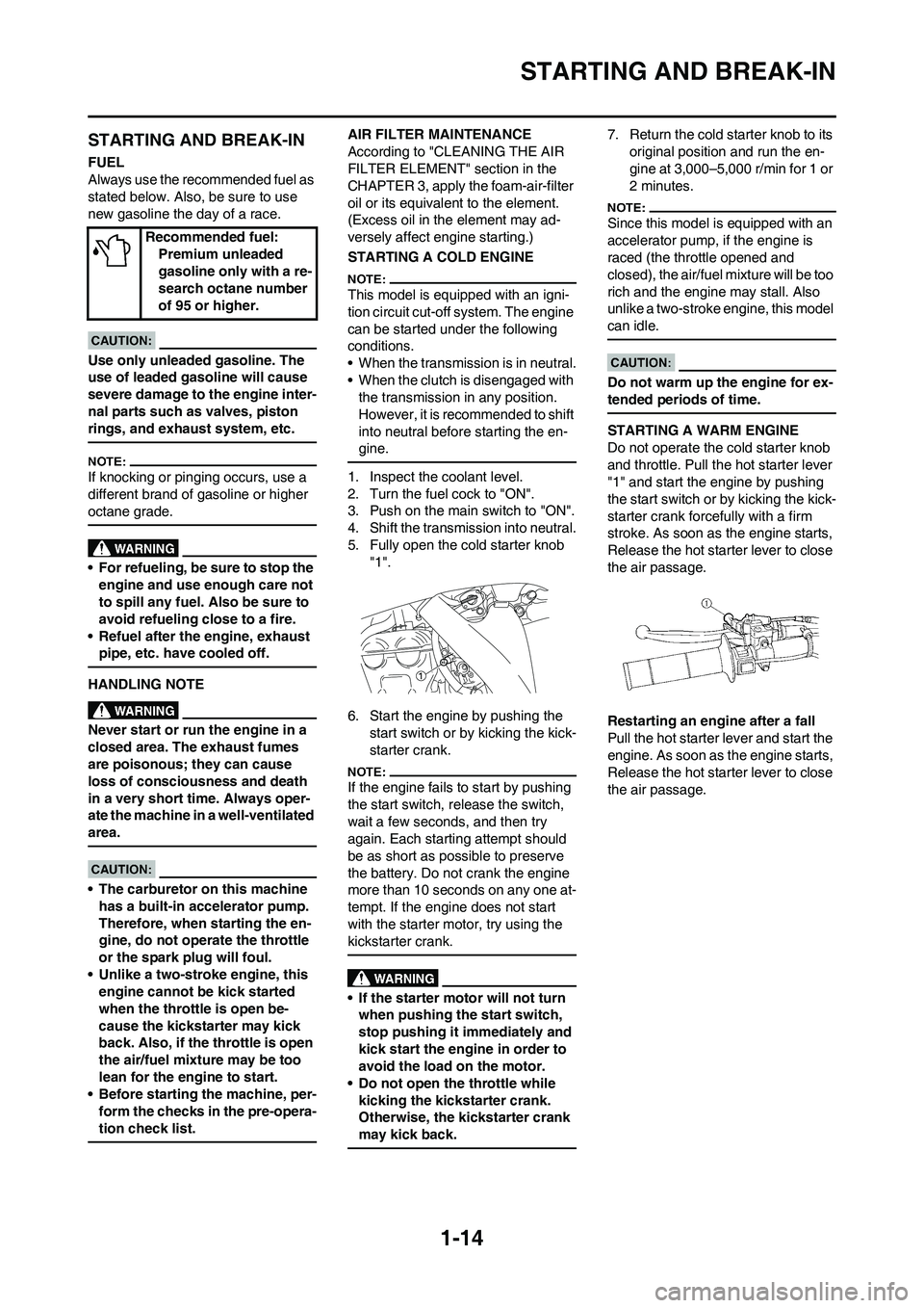
5. Fully open the cold starter knob
"1".
6. Start the engine by pushing the
start switch or by kicking the kick-
starter crank.
If the engine fails to start by pushing
the start switch, release the switch,
wait a few seconds, and then try
again. Each starting attempt should
be as short as possible to preserve
the battery. Do not crank the engine
more than 10 seconds on any one at-
tempt. If the engine does not start
with the starter motor, try using the
kickstarter crank.
• If the starter motor will not turn
when pushing the start switch,
stop pushing it immediately and
kick start the engine in order to
avoid the load on the motor.
• Do not open the throttle while
kicking the kickstarter crank.
Otherwise, the kickstarter crank
may kick back.
7. Return the cold starter knob to its
original position and run the en-
gine at 3,000–5,000 r/min for 1 or
2 minutes.
Since this model is equipped with an
accelerator pump, if the engine is
raced (the throttle opened and
closed), the air/fuel mixture will be too
rich and the engine may stall. Also
unlike a two-stroke engine, this model
can idle.
Do not warm up the engine for ex-
tended periods of time.
STARTING A WARM ENGINE
Do not operate the cold starter knob
and throttle. Pull the hot starter lever
"1" and start the engine by pushing
the start switch or by kicking the kick-
starter crank forcefully with a firm
stroke. As soon as the engine starts,
Release the hot starter lever to close
the air passage.
Restarting an engine after a fall
Pull the hot starter lever and start the
engine. As soon as the engine starts,
Release the hot starter lever to close
the air passage. Recommended fuel:
Premium unleaded
gasoline only with a re-
search octane number
of 95 or higher.
Page 26 of 224
1-16
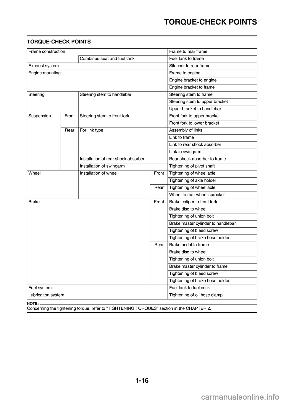
TORQUE-CHECK POINTS
TORQUE-CHECK POINTS
Concerning the tightening torque, refer to "TIGHTENING TORQUES" section in the CHAPTER 2.
Frame construction Frame to rear frame
Combined seat and fuel tank Fuel tank to frame
Exhaust system Silencer to rear frame
Engine mounting Frame to engine
Engine bracket to engine
Engine bracket to frame
Steering Steering stem to handlebar Steering stem to frame
Steering stem to upper bracket
Upper bracket to handlebar
Suspension Front Steering stem to front fork Front fork to upper bracket
Front fork to lower bracket
Rear For link type Assembly of links
Link to frame
Link to rear shock absorber
Link to swingarm
Installation of rear shock absorber Rear shock absorber to frame
Installation of swingarm Tightening of pivot shaft
Wheel Installation of wheel Front Tightening of wheel axle
Tightening of axle holder
Rear Tightening of wheel axle
Wheel to rear wheel sprocket
Brake Front Brake caliper to front fork
Brake disc to wheel
Tightening of union bolt
Brake master cylinder to handlebar
Tightening of bleed screw
Tightening of brake hose holder
Rear Brake pedal to frame
Brake disc to wheel
Tightening of union bolt
Brake master cylinder to frame
Tightening of bleed screw
Tightening of brake hose holder
Fuel system Fuel tank to fuel cock
Lubrication system Tightening of oil hose clamp
Page 27 of 224

1-17
CLEANING AND STORAGE
CLEANING AND STORAGE
CLEANING
Frequent cleaning of your machine
will enhance its appearance, maintain
good overall performance, and ex-
tend the life of many components.
1. Before washing the machine,
block off the end of the exhaust
pipe to prevent water from enter-
ing. A plastic bag secured with a
rubber band may be used for this
purpose.
2. If the engine is excessively
greasy, apply some degreaser to
it with a paint brush. Do not apply
degreaser to the chain, sprockets,
or wheel axles.
3. Rinse the dirt and degreaser off
with a garden hose; use only
enough pressure to do the job.
Excessive hose pressure may
cause water seepage and contami-
nation of wheel bearings, front
forks, brakes and transmission
seals. Many expensive repair bills
have resulted from improper high
pressure detergent applications
such as those available in coin-op-
erated car washers.
4. After the majority of the dirt has
been hosed off, wash all surfaces
with warm water and a mild deter-
gent. Use an old toothbrush to
clean hard-to-reach places.
5. Rinse the machine off immediate-
ly with clean water, and dry all
surfaces with a soft towel or cloth.
6. Immediately after washing, re-
move excess water from the
chain with a paper towel and lubri-
cate the chain to prevent rust.
7. Clean the seat with a vinyl uphol-
stery cleaner to keep the cover
pliable and glossy.
8. Automotive wax may be applied
to all painted or chromed surfac-
es. Avoid combination cleaner-
waxes, as they may contain abra-
sives.
9. After completing the above, start
the engine and allow it to idle for
several minutes.STORAGE
If your machine is to be stored for 60
days or more, some preventive mea-
sures must be taken to avoid deterio-
ration. After cleaning the machine
thoroughly, prepare it for storage as
follows:
1. Drain the fuel tank, fuel lines, and
the carburetor float bowl.
2. Remove the spark plug, pour a ta-
blespoon of SAE 10W-30 motor
oil in the spark plug hole, and re-
install the plug. With the engine
stop switch pushed in, kick the en-
gine over several times to coat the
cylinder walls with oil.
3. Remove the drive chain, clean it
thoroughly with solvent, and lubri-
cate it. Reinstall the chain or store
it in a plastic bag tied to the frame.
4. Lubricate all control cables.
5. Block the frame up to raise the
wheels off the ground.
6. Tie a plastic bag over the exhaust
pipe outlet to prevent moisture
from entering.
7. If the machine is to be stored in a
humid or salt-air environment,
coat all exposed metal surfaces
with a film of light oil. Do not apply
oil to rubber parts or the seat cov-
er.
Make any necessary repairs before
the machine is stored.
Page 28 of 224

2-1
GENERAL SPECIFICATIONS
SPECIFICATIONS
GENERAL SPECIFICATIONS
Model name: WR450FX (CDN, AUS, NZ)
WR450F (EUROPE, ZA)
Model code number: 5TJK (CDN)
5TJL (EUROPE)
5TJM (AUS, NZ, ZA)
Dimensions: CDN, ZA AUS, NZ EUROPE
Overall length 2,175 mm (85.63
in) 2,190 mm (86.22
in)2,200 mm (86.61
in)
Overall width 825 mm (32.48 in)←←
Overall height 1,295 mm (50.98
in)1,300 mm (51.18
in)1,305 mm (51.38
in)
Seat height 980 mm (38.58 in) 990 mm (38.98 in)←
Wheelbase 1,485 mm (58.46
in)←1,500 mm (59.06
in)
Minimum ground clearance 365 mm (14.37 in) 370 mm (14.57 in) 375 mm (14.76 in)
Dry weight:
Without oil and fuel 112.5 kg (248.0 lb)
Engine:
Engine type Liquid cooled 4-stroke, DOHC
Cylinder arrangement Single cylinder, forward inclined
Displacement 449 cm
3 (15.8 Imp oz, 15.2 US oz)
Bore × stroke 95.0 × 63.4 mm (3.74 × 2.50 in)
Compression ratio 12.3 : 1
Starting system Kick and electric starter
Lubrication system: Dry sump
Oil type or grade:
Engine oil (For CDN)
Yamalube 4, SAE10W30 or SAE20W40
Yamalube 4-R, SAE10W50
API service SG type or higher,
JASO standard MA
Page 29 of 224
2-2
GENERAL SPECIFICATIONS
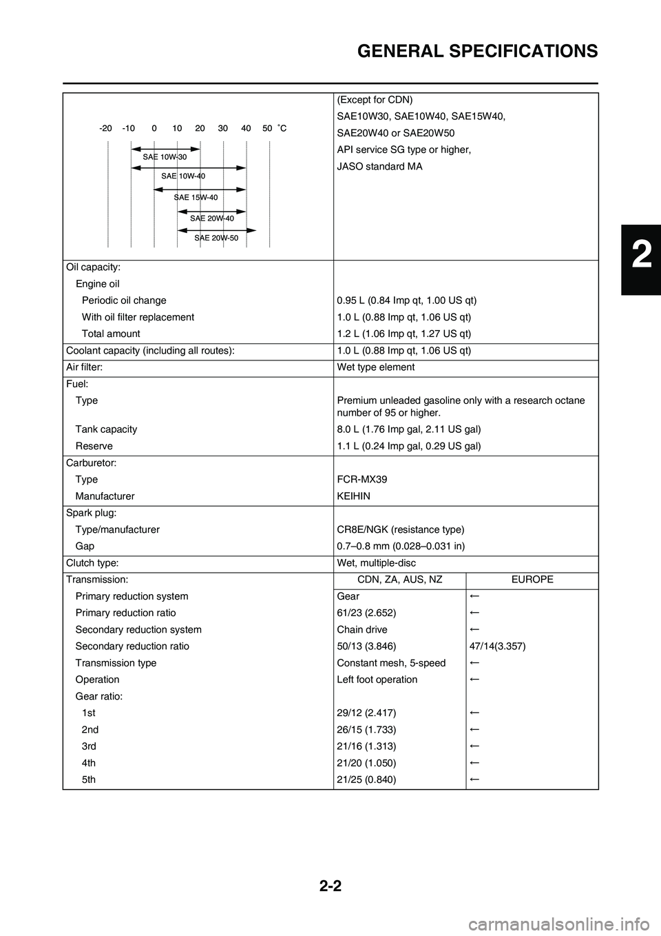
(Except for CDN)
SAE10W30, SAE10W40, SAE15W40,
SAE20W40 or SAE20W50
API service SG type or higher,
JASO standard MA
Oil capacity:
Engine oil
Periodic oil change 0.95 L (0.84 Imp qt, 1.00 US qt)
With oil filter replacement 1.0 L (0.88 Imp qt, 1.06 US qt)
Total amount 1.2 L (1.06 Imp qt, 1.27 US qt)
Coolant capacity (including all routes): 1.0 L (0.88 Imp qt, 1.06 US qt)
Air filter: Wet type element
Fuel:
Type Premium unleaded gasoline only with a research octane
number of 95 or higher.
Tank capacity 8.0 L (1.76 Imp gal, 2.11 US gal)
Reserve 1.1 L (0.24 Imp gal, 0.29 US gal)
Carburetor:
Type FCR-MX39
Manufacturer KEIHIN
Spark plug:
Type/manufacturer CR8E/NGK (resistance type)
Gap 0.7–0.8 mm (0.028–0.031 in)
Clutch type: Wet, multiple-disc
Transmission: CDN, ZA, AUS, NZ EUROPE
Primary reduction system Gear←
Primary reduction ratio 61/23 (2.652)←
Secondary reduction system Chain drive←
Secondary reduction ratio 50/13 (3.846) 47/14(3.357)
Transmission type Constant mesh, 5-speed←
Operation Left foot operation←
Gear ratio:
1st 29/12 (2.417)←
2nd 26/15 (1.733)←
3rd 21/16 (1.313)←
4th 21/20 (1.050)←
5th 21/25 (0.840)←
2
Page 41 of 224
2-14
TIGHTENING TORQUES
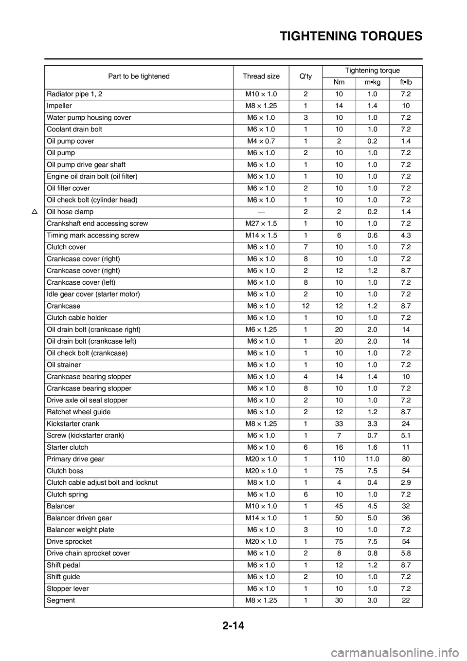
Radiator pipe 1, 2 M10 × 1.0 2 10 1.0 7.2
Impeller M8 × 1.25 1 14 1.4 10
Water pump housing cover M6 × 1.0 3 10 1.0 7.2
Coolant drain bolt M6 × 1.0 1 10 1.0 7.2
Oil pump cover M4 × 0.7 1 2 0.2 1.4
Oil pump M6 × 1.0 2 10 1.0 7.2
Oil pump drive gear shaft M6 × 1.0 1 10 1.0 7.2
Engine oil drain bolt (oil filter) M6 × 1.0 1 10 1.0 7.2
Oil filter cover M6 × 1.0 2 10 1.0 7.2
Oil check bolt (cylinder head) M6 × 1.0 1 10 1.0 7.2
△Oil hose clamp — 2 2 0.2 1.4
Crankshaft end accessing screw M27 × 1.5 1 10 1.0 7.2
Timing mark accessing screw M14 × 1.5 1 6 0.6 4.3
Clutch cover M6 × 1.0 7 10 1.0 7.2
Crankcase cover (right) M6 × 1.0 8 10 1.0 7.2
Crankcase cover (right) M6 × 1.0 2 12 1.2 8.7
Crankcase cover (left) M6 × 1.0 8 10 1.0 7.2
Idle gear cover (starter motor) M6 × 1.0 2 10 1.0 7.2
Crankcase M6 × 1.0 12 12 1.2 8.7
Clutch cable holder M6 × 1.0 1 10 1.0 7.2
Oil drain bolt (crankcase right) M6 × 1.25 1 20 2.0 14
Oil drain bolt (crankcase left) M6 × 1.0 1 20 2.0 14
Oil check bolt (crankcase) M6 × 1.0 1 10 1.0 7.2
Oil strainer M6 × 1.0 1 10 1.0 7.2
Crankcase bearing stopper M6 × 1.0 4 14 1.4 10
Crankcase bearing stopper M6 × 1.0 8 10 1.0 7.2
Drive axle oil seal stopper M6 × 1.0 2 10 1.0 7.2
Ratchet wheel guide M6 × 1.0 2 12 1.2 8.7
Kickstarter crank M8 × 1.25 1 33 3.3 24
Screw (kickstarter crank) M6 × 1.0 1 7 0.7 5.1
Starter clutch M6 × 1.0 6 16 1.6 11
Primary drive gear M20 × 1.0 1 110 11.0 80
Clutch boss M20 × 1.0 1 75 7.5 54
Clutch cable adjust bolt and locknut M8 × 1.0 1 4 0.4 2.9
Clutch spring M6 × 1.0 6 10 1.0 7.2
Balancer M10 × 1.0 1 45 4.5 32
Balancer driven gear M14 × 1.0 1 50 5.0 36
Balancer weight plate M6 × 1.0 3 10 1.0 7.2
Drive sprocket M20 × 1.0 1 75 7.5 54
Drive chain sprocket cover M6 × 1.0 2 8 0.8 5.8
Shift pedal M6 × 1.0 1 12 1.2 8.7
Shift guide M6 × 1.0 2 10 1.0 7.2
Stopper lever M6 × 1.0 1 10 1.0 7.2
Segment M8 × 1.25 1 30 3.0 22Part to be tightened Thread size Q'tyTightening torque
Nm m•kg ft•lb