YAMAHA WR 450F 2008 Owners Manual
Manufacturer: YAMAHA, Model Year: 2008, Model line: WR 450F, Model: YAMAHA WR 450F 2008Pages: 224, PDF Size: 13.7 MB
Page 101 of 224
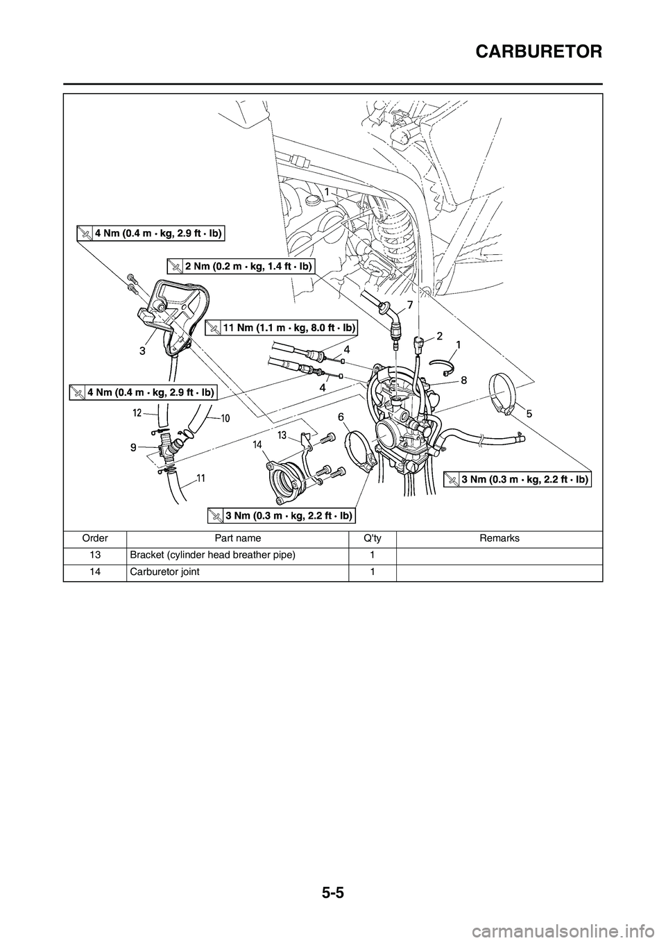
5-5
CARBURETOR
13 Bracket (cylinder head breather pipe) 1
14 Carburetor joint 1 Order Part name Q'ty Remarks
Page 102 of 224
5-6
CARBURETOR
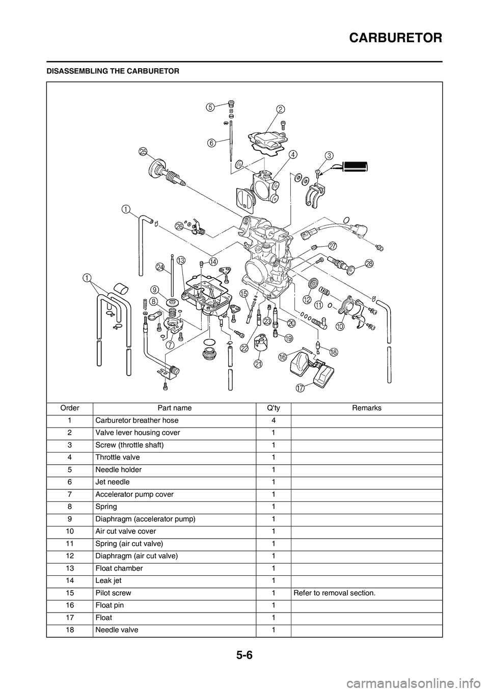
DISASSEMBLING THE CARBURETOR
Order Part name Q'ty Remarks
1 Carburetor breather hose 4
2 Valve lever housing cover 1
3 Screw (throttle shaft) 1
4 Throttle valve 1
5 Needle holder 1
6 Jet needle 1
7 Accelerator pump cover 1
8Spring 1
9 Diaphragm (accelerator pump) 1
10 Air cut valve cover 1
11 Spring (air cut valve) 1
12 Diaphragm (air cut valve) 1
13 Float chamber 1
14 Leak jet 1
15 Pilot screw 1 Refer to removal section.
16 Float pin 1
17 Float 1
18 Needle valve 1
Page 103 of 224
5-7
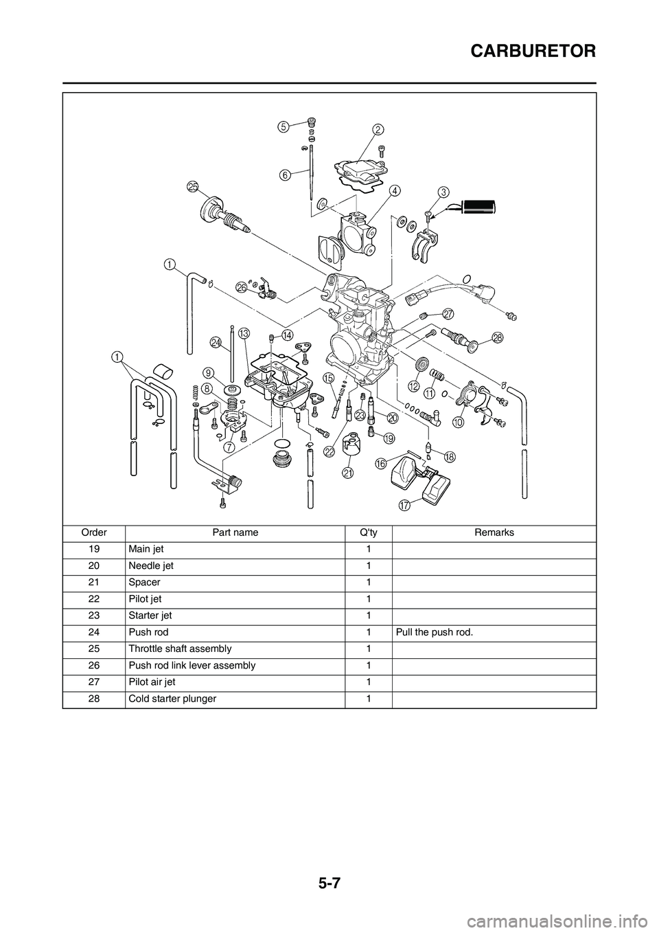
CARBURETOR
19 Main jet 1
20 Needle jet 1
21 Spacer 1
22 Pilot jet 1
23 Starter jet 1
24 Push rod 1 Pull the push rod.
25 Throttle shaft assembly 1
26 Push rod link lever assembly 1
27 Pilot air jet 1
28 Cold starter plunger 1 Order Part name Q'ty Remarks
Page 104 of 224
5-8
CARBURETOR
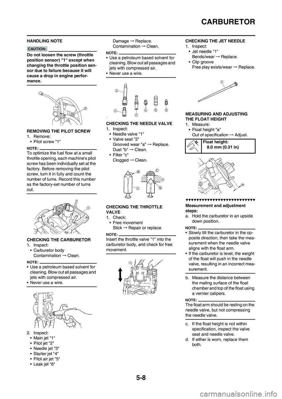
HANDLING NOTE
Do not loosen the screw (throttle
position sensor) "1" except when
changing the throttle position sen-
sor due to failure because it will
cause a drop in engine perfor-
mance.
REMOVING THE PILOT SCREW
1. Remove:
• Pilot screw "1"
To optimize the fuel flow at a small
throttle opening, each machine's pilot
screw has been individually set at the
factory. Before removing the pilot
screw, turn it in fully and count the
number of turns. Record this number
as the factory-set number of turns
out.
CHECKING THE CARBURETOR
1. Inspect:
• Carburetor body
Contamination→Clean.
• Use a petroleum based solvent for
cleaning. Blow out all passages and
jets with compressed air.
• Never use a wire.
2. Inspect:
•Main jet "1"
• Pilot jet "2"
• Needle jet "3"
• Starter jet "4"
• Pilot air jet "5"
• Leak jet "6"Damage→Replace.
Contamination→Clean.
• Use a petroleum based solvent for
cleaning. Blow out all passages and
jets with compressed air.
• Never use a wire.
CHECKING THE NEEDLE VALVE
1. Inspect:
• Needle valve "1"
• Valve seat "2"
Grooved wear "a" →Replace.
Dust "b" →Clean.
• Filter "c"
Clogged→Clean.
CHECKING THE THROTTLE
VALVE
1. Check:
• Free movement
Stick→Repair or replace.
Insert the throttle valve "1" into the
carburetor body, and check for free
movement.
CHECKING THE JET NEEDLE
1. Inspect:
• Jet needle "1"
Bends/wear→Replace.
• Clip groove
Free play exists/wear→Replace.
MEASURING AND ADJUSTING
THE FLOAT HEIGHT
1. Measure:
• Float height "a"
Out of specification→Adjust.
Measurement and adjustment
steps:
a. Hold the carburetor in an upside
down position.
• Slowly tilt the carburetor in the op-
posite direction, then take the mea-
surement when the needle valve
aligns with the float arm.
• If the carburetor is level, the weight
of the float will push in the needle
valve, resulting in an incorrect mea-
surement.
b. Measure the distance between
the mating surface of the float
chamber and top of the float using
a vernier calipers.
The float arm should be resting on the
needle valve, but not compressing
the needle valve.
c. If the float height is not within
specification, inspect the valve
seat and needle valve.
d. If either is worn, replace them
both.
Float height:
8.0 mm (0.31 in)
Page 105 of 224

5-9
CARBURETOR
e. If both are fine, adjust the float
height by bending the float tab "b"
on the float.
f. Recheck the float height.
CHECKING THE FLOAT
1. Inspect:
• Float "1"
Damage→Replace.
CHECKING THE STARTER
PLUNGER
1. Inspect:
• Cold starter plunger "1"
• Hot starter plunger "2"
Wear/damage→Replace.
CHECKING THE ACCELERATOR
PUMP
1. Inspect:
• Diaphragm (accelerator pump)
"1"
• Spring (accelerator pump) "2"
• Accelerator pump cover "3"
• O-ring "4"
• Push rod "5"
Tears (diaphragm)/damage→Re-
place.
Dirt→Clean.2. Inspect:
• Throttle shaft "1"
• Spring "2"
• Lever 1 "3"
• Spring 1 "4"
• Lever 2 "5"
• Spring 2 "6"
Dirt→Clean.
CHECKING THE AIR CUT VALVE
1. Inspect:
• Diaphragm (air cut valve) "1"
• Spring (air cut valve) "2"
• Air cut valve cover "3"
• O-ring "4"
Tears (diaphragm)/damage→Re-
place.
ASSEMBLING THE CARBURETOR
1. Install:
• Cold starter plunger
2. Install:
•Pilot air jet "1"
3. Install:
• Spring 1 "1"
• Lever 1 "2"
To lever 2 "3".
Make sure the spring 1 fits on the
stopper "a" of the lever 2.
4. Install:
• Spring 2 "1"
To lever 2 "2".
5. Install:
• Push rod link lever assembly "1"
Make sure the stopper "a" of the
spring 2 fits into the recess "b" in the
carburetor.
6. Install:
• Washer "1"
• Circlip "2"
7. Install:
• Spring "1"
To throttle shaft "2".
Install the bigger hook "a" of the
spring fits on the stopper "b" of the
throttle shaft pulley.
8. Install:
• Throttle shaft assembly "1"
• Washer (metal) "2"
• Washer (resin) "3"
• Valve lever "4"
Page 106 of 224

5-10
CARBURETOR
• Apply the fluorochemical grease on
the bearings.
• Fit the projection "a" on the throttle
shaft assembly into the slot "b" in
the throttle position sensor.
• Make sure the stopper "c" of the
spring fits into the recess in the car-
buretor.
• Turn the throttle shaft assembly left
while holding down the lever 1 "5"
and fit the throttle stop screw tip "d"
to the stopper "e" of the throttle
shaft assembly pulley.
9. Install:
• Push rod "1"
While holding down the lever 1 "2", in-
sert the push rod farthest into the car-
buretor.
10. Install:
• Starter jet "1"
• Pilot jet "2"
• Spacer "3"
• Needle jet "4"
•Main jet "5"11. Install:
• Needle valve "1"
•Float "2"
• Float pin "3"
• After installing the needle valve to
the float, install them to the carbure-
tor.
• Check the float for smooth move-
ment.
12. Install:
• Pilot screw "1"
• Spring "2"
• Washer "3"
• O-ring "4"
Note the following installation
points:
a. Turn in the pilot screw until it is
lightly seated.
b. Turn out the pilot screw by the
number of turns recorded before
removing.
13. Install:
• O-ring
• Leak jet "1"
• Float chamber "2"
• Bolt (float chamber) "3"
• Cable holder (throttle stop screw
cable) "4"
• Hose holder (carburetor breather
hose) "5"14. Install:
• Diaphragm (air cut valve) "1"
• Spring (air cut valve) "2"
• O-ring "3"
• Air cut valve cover "4"
• Holder (cylinder head breather
hose) "5"
• Screw (air cut valve cover) "6"
15. Install:
• Diaphragm (accelerator pump)
"1"
• Spring "2"
• O-ring "3"
• Accelerator pump cover "4"
• Hose holder (drain hose) "5"
• Screw (accelerator pump cover)
"6"
Install the diaphragm (accelerator
pump) with its mark "a" facing the
spring.
16. Install:
• Jet needle "1"
•Collar "2"
• Spring "3"
• Needle holder "4"
• Throttle valve plate "5"
To throttle valve "6".
Pilot screw (example):
2 turns out
Page 107 of 224
5-11
CARBURETOR
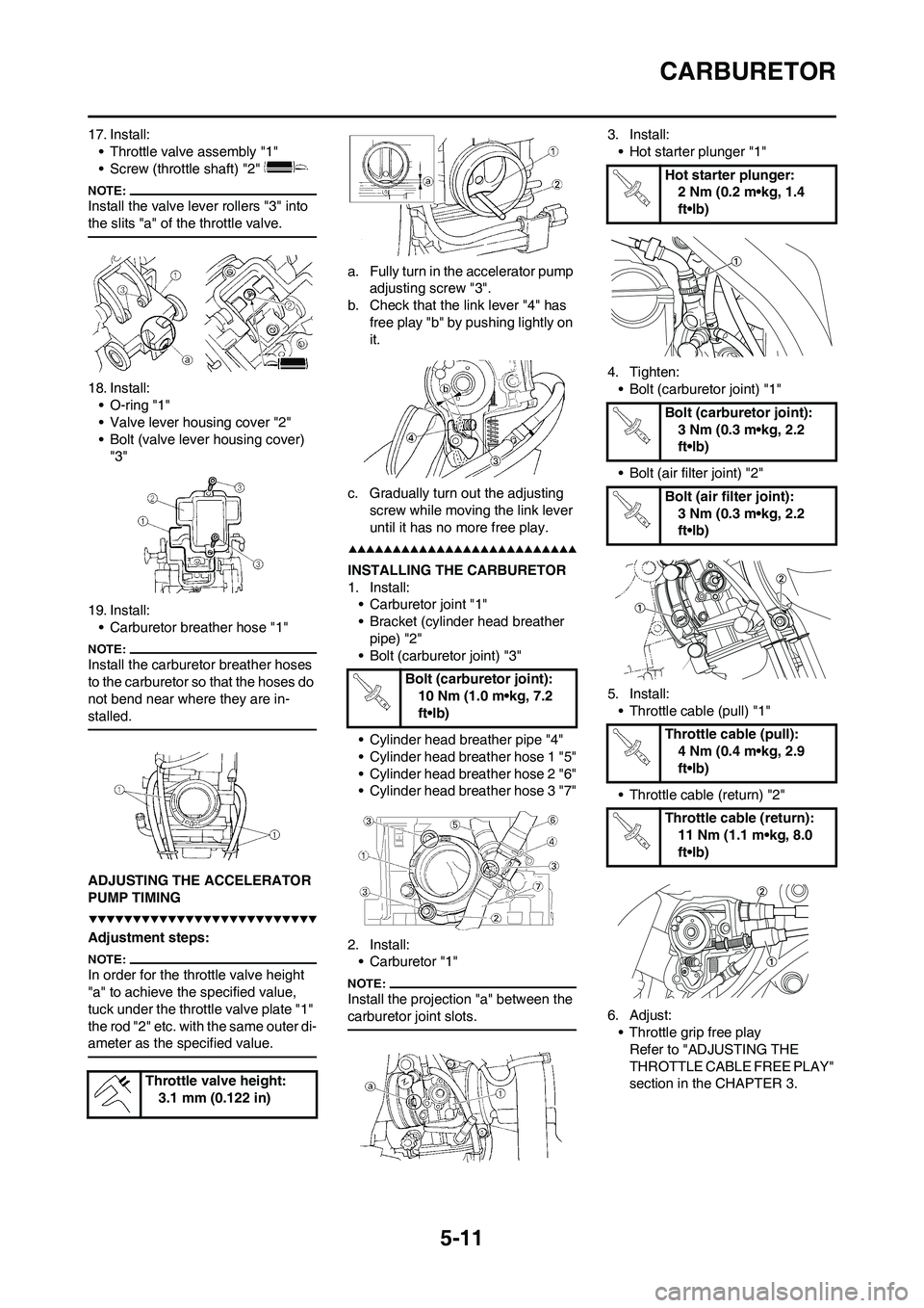
17. Install:
• Throttle valve assembly "1"
• Screw (throttle shaft) "2"
Install the valve lever rollers "3" into
the slits "a" of the throttle valve.
18. Install:
• O-ring "1"
• Valve lever housing cover "2"
• Bolt (valve lever housing cover)
"3"
19. Install:
• Carburetor breather hose "1"
Install the carburetor breather hoses
to the carburetor so that the hoses do
not bend near where they are in-
stalled.
ADJUSTING THE ACCELERATOR
PUMP TIMING
Adjustment steps:
In order for the throttle valve height
"a" to achieve the specified value,
tuck under the throttle valve plate "1"
the rod "2" etc. with the same outer di-
ameter as the specified value.
a. Fully turn in the accelerator pump
adjusting screw "3".
b. Check that the link lever "4" has
free play "b" by pushing lightly on
it.
c. Gradually turn out the adjusting
screw while moving the link lever
until it has no more free play.
INSTALLING THE CARBURETOR
1. Install:
• Carburetor joint "1"
• Bracket (cylinder head breather
pipe) "2"
• Bolt (carburetor joint) "3"
• Cylinder head breather pipe "4"
• Cylinder head breather hose 1 "5"
• Cylinder head breather hose 2 "6"
• Cylinder head breather hose 3 "7"
2. Install:
• Carburetor "1"
Install the projection "a" between the
carburetor joint slots.
3. Install:
• Hot starter plunger "1"
4. Tighten:
• Bolt (carburetor joint) "1"
• Bolt (air filter joint) "2"
5. Install:
• Throttle cable (pull) "1"
• Throttle cable (return) "2"
6. Adjust:
• Throttle grip free play
Refer to "ADJUSTING THE
THROTTLE CABLE FREE PLAY"
section in the CHAPTER 3. Throttle valve height:
3.1 mm (0.122 in)
Bolt (carburetor joint):
10 Nm (1.0 m•kg, 7.2
ft•lb)
Hot starter plunger:
2 Nm (0.2 m•kg, 1.4
ft•lb)
Bolt (carburetor joint):
3 Nm (0.3 m•kg, 2.2
ft•lb)
Bolt (air filter joint):
3 Nm (0.3 m•kg, 2.2
ft•lb)
Throttle cable (pull):
4 Nm (0.4 m•kg, 2.9
ft•lb)
Throttle cable (return):
11 Nm (1.1 m•kg, 8.0
ft•lb)
Page 108 of 224

5-12
CARBURETOR
7. Install:
• Throttle cable cover "1"
• Bolt (throttle cable cover) "2"
8. Install:
• Throttle position sensor lead cou-
pler "1"
• Clamp "2"
Refer to "CABLE ROUTING DIA-
GRAM" section in the CHAPTER
2.
9. Install:
• Clamp "1"
Refer to "CABLE ROUTING DIA-
GRAM" section in the CHAPTER
2.Bolt (throttle cable cov-
er):
4 Nm (0.4 m•kg, 2.9
ft•lb)
Page 109 of 224
5-13
AIR INDICTOIN SYSTEM
AIR INDICTOIN SYSTEM
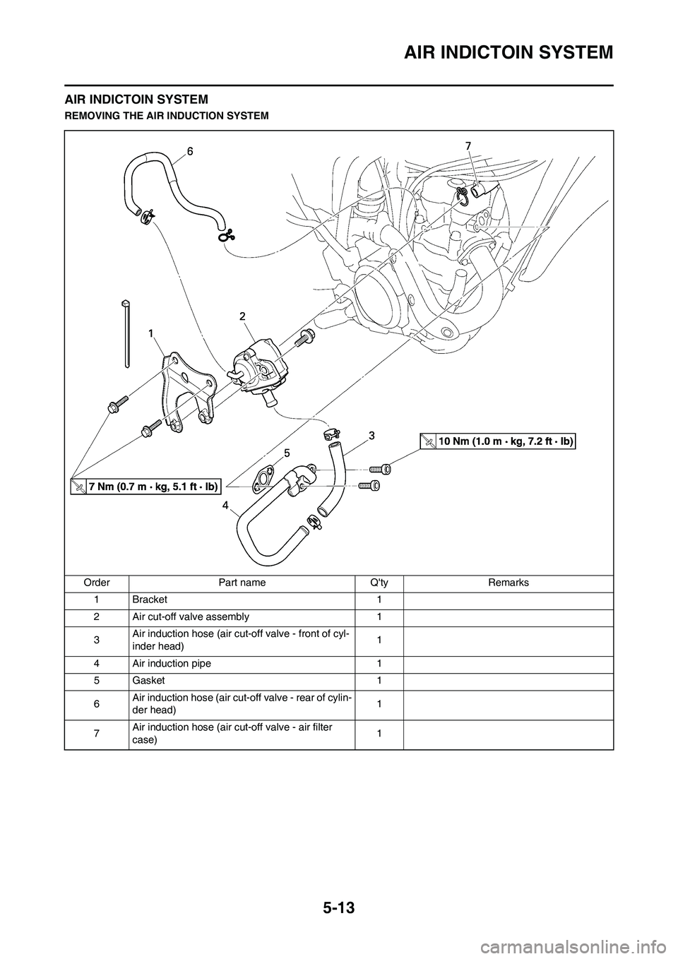
REMOVING THE AIR INDUCTION SYSTEM
Order Part name Q'ty Remarks
1 Bracket 1
2 Air cut-off valve assembly 1
3Air induction hose (air cut-off valve - front of cyl-
inder head)1
4 Air induction pipe 1
5 Gasket 1
6Air induction hose (air cut-off valve - rear of cylin-
der head)1
7Air induction hose (air cut-off valve - air filter
case)1
Page 110 of 224
5-14
AIR INDICTOIN SYSTEM
CHECKING THE AIR INDUCTION
SYSTEM
1. Inspect:
• Air induction hose
Crack/damage→Replace.
• Air induction pipe
Crack/damage→Replace.
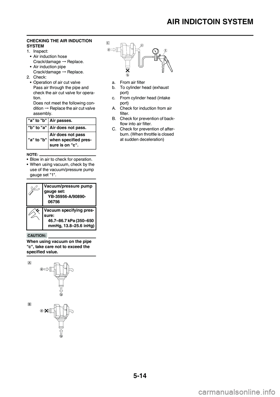
2. Check:
• Operation of air cut valve
Pass air through the pipe and
check the air cut valve for opera-
tion.
Does not meet the following con-
dition→Replace the air cut valve
assembly.
• Blow in air to check for operation.
• When using vacuum, check by the
use of the vacuum/pressure pump
gauge set "1".
When using vacuum on the pipe
"c", take care not to exceed the
specified value.
a. From air filter
b. To cylinder head (exhaust
port)
c. From cylinder head (intake
port)
A. Check for induction from air
filter.
B. Check for prevention of back-
flow into air filter.
C. Check for prevention of after-
burn. (When throttle is closed
at sudden deceleration) "a" to "b" Air passes.
"b" to "a" Air does not pass.
"a" to "b"Air does not pass
when specified pres-
sure is on "c".
Vacuum/pressure pump
gauge set:
YB-35956-A/90890-
06756
Vacuum specifying pres-
sure:
46.7–86.7 kPa (350–650
mmHg, 13.8–25.6 inHg)