YAMAHA WR 450F 2008 Owners Manual
Manufacturer: YAMAHA, Model Year: 2008, Model line: WR 450F, Model: YAMAHA WR 450F 2008Pages: 224, PDF Size: 13.7 MB
Page 111 of 224
5-15
CAMSHAFTS
CAMSHAFTS
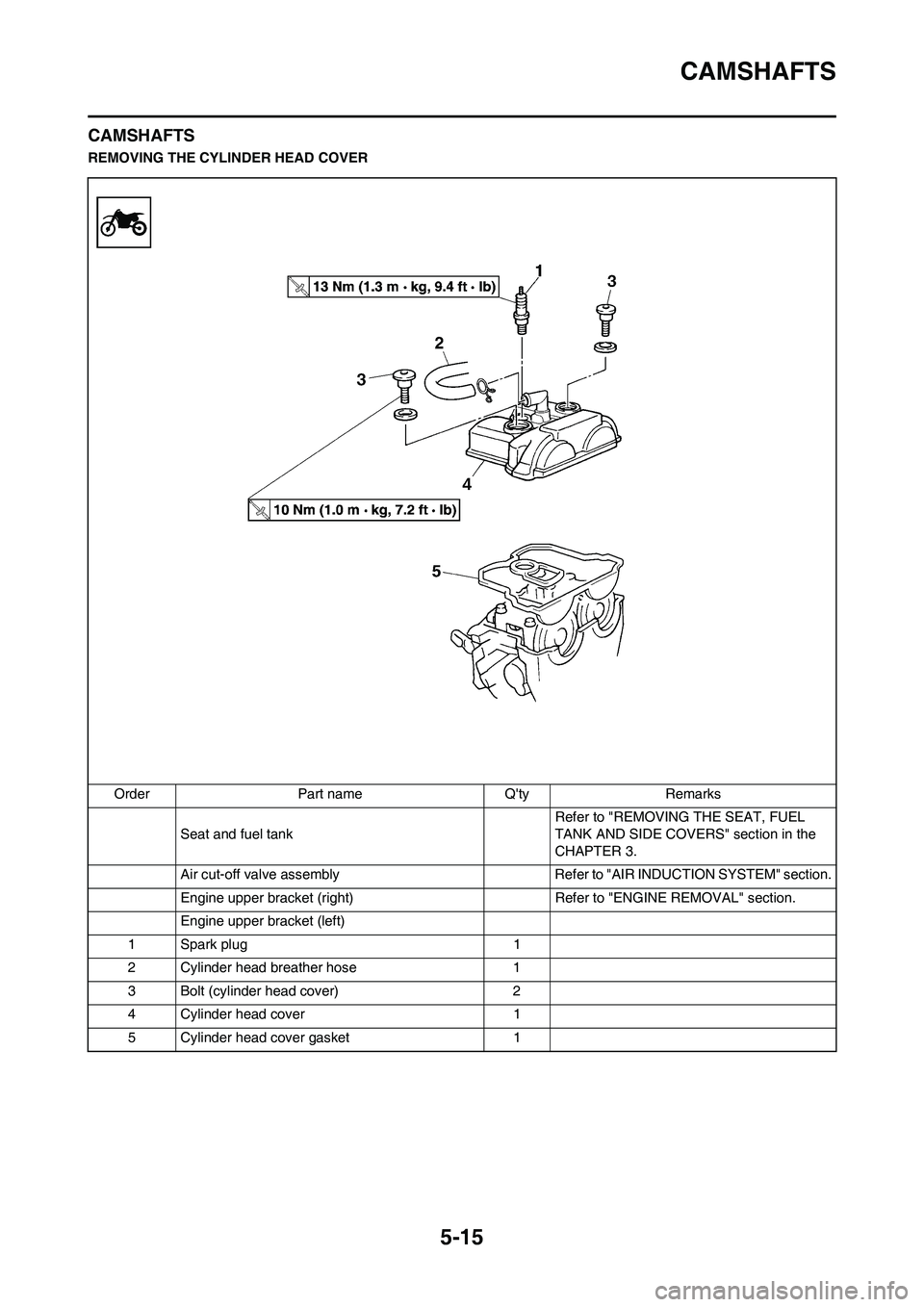
REMOVING THE CYLINDER HEAD COVER
Order Part name Q'ty Remarks
Seat and fuel tank Refer to "REMOVING THE SEAT, FUEL
TANK AND SIDE COVERS" section in the
CHAPTER 3.
Air cut-off valve assembly Refer to "AIR INDUCTION SYSTEM" section.
Engine upper bracket (right) Refer to "ENGINE REMOVAL" section.
Engine upper bracket (left)
1 Spark plug 1
2 Cylinder head breather hose 1
3 Bolt (cylinder head cover) 2
4 Cylinder head cover 1
5 Cylinder head cover gasket 1
Page 112 of 224
5-16
CAMSHAFTS
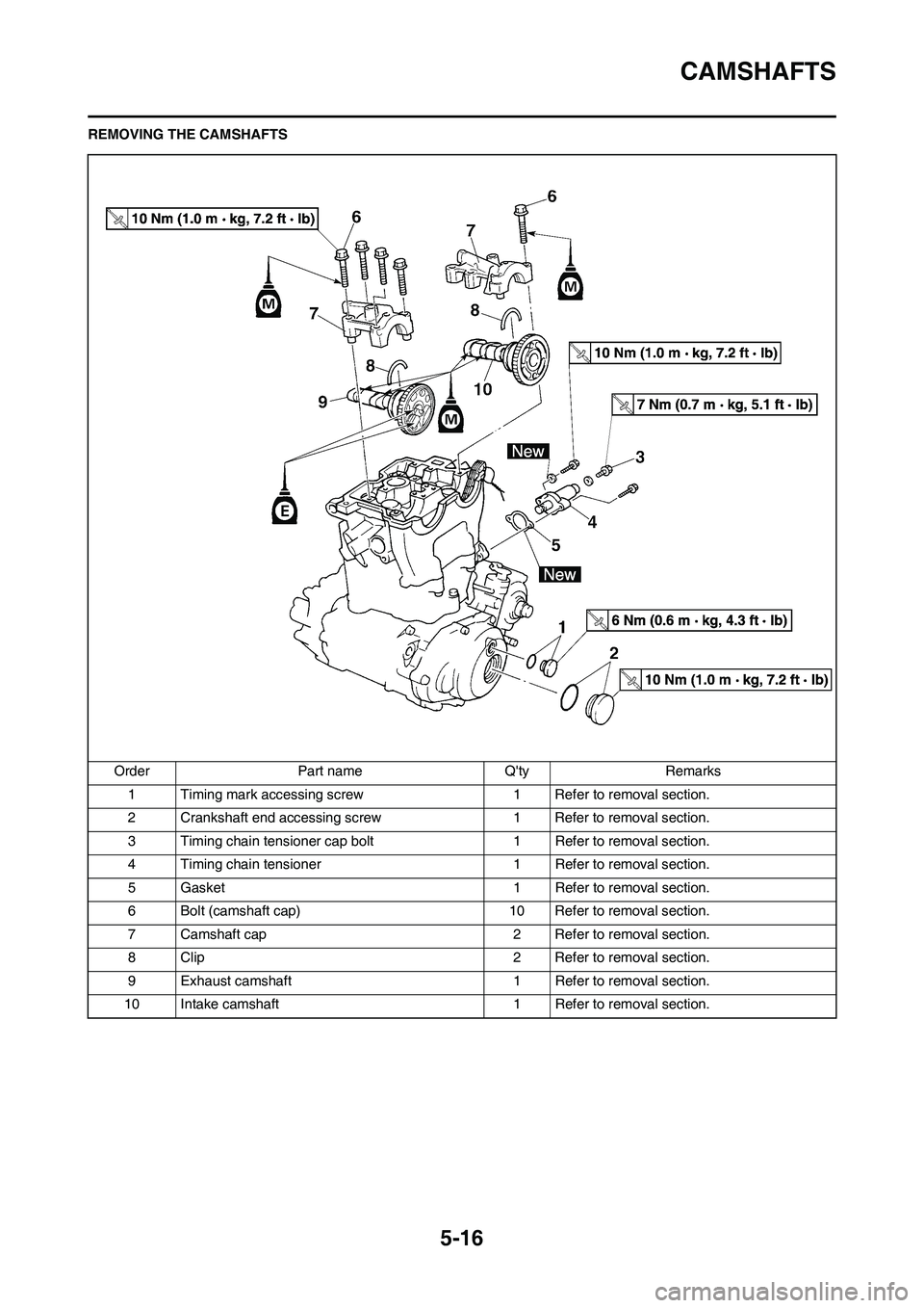
REMOVING THE CAMSHAFTS
Order Part name Q'ty Remarks
1 Timing mark accessing screw1 Refer to removal section.
2 Crankshaft end accessing screw 1 Refer to removal section.
3 Timing chain tensioner cap bolt 1 Refer to removal section.
4 Timing chain tensioner 1 Refer to removal section.
5 Gasket 1 Refer to removal section.
6 Bolt (camshaft cap) 10 Refer to removal section.
7 Camshaft cap 2 Refer to removal section.
8 Clip 2 Refer to removal section.
9 Exhaust camshaft 1 Refer to removal section.
10 Intake camshaft 1 Refer to removal section.
Page 113 of 224

5-17
CAMSHAFTS
REMOVING THE CAMSHAFT
1. Remove:
• Timing mark accessing screw "1"
• Crankshaft end accessing screw
"2"
2. Align:
• T.D.C. mark
With align mark.
Checking steps:
a. Turn the crankshaft counterclock-
wise with a wrench.
b. Align the T.D.C. mark "a" on the
rotor with the align mark "b" on the
crankcase cover when piston is at
T.D.C. on compression stroke.
In order to be sure that the piston is at
Top Dead Center, the punch mark "c"
on the exhaust camshaft and the
punch mark "d" on the intake cam-
shaft must align with the cylinder
head surface, as shown in the illustra-
tion.
3. Remove:
• Timing chain tensioner cap bolt
"1"
• Timing chain tensioner "2"
• Gasket4. Remove:
• Bolt (camshaft cap) "1"
• Camshaft cap "2"
• Clip
Remove the bolts (camshaft cap) in a
crisscross pattern, working from the
outside in.
The bolts (camshaft cap) must be
removed evenly to prevent dam-
age to the cylinder head, cam-
shafts or camshaft caps.
5. Remove:
• Exhaust camshaft "1"
• Intake camshaft "2"
Attach a wire "3" to the timing chain to
prevent it from falling into the crank-
case.
CHECKING THE CAMSHAFT
1. Inspect:
• Cam lobe
Pitting/scratches/blue discolora-
tion→Replace.
2. Measure:
• Cam lobe length "a" and "b"
Out of specification→Replace.3. Measure:
• Runout (camshaft)
Out of specification→Replace.
4. Measure:
• Camshaft-to-cap clearance
Out of specification→Measure
camshaft outside diameter.
Cam lobes length:
Intake "a":
30.100–30.200 mm
(1.1850–1.1890 in)
30.000 mm (1.1811 in)
Intake "b":
22.450–22.550 mm
(0.8839–0.8878 in)
22.350 mm (0.8799 in)
Exhaust "a":
30.200–30.300 mm
(1.1890–1.1929 in)
30.100 mm (1.1850 in)
Exhaust "b":
22.450–22.550 mm
(0.8839–0.8878 in)
22.350 mm (0.8799 in)
Runout (camshaft):
Less than 0.03 mm
(0.0012 in)
Page 114 of 224

5-18
CAMSHAFTS
Measurement steps:
a. Install the camshaft onto the cylin-
der head.
b. Position a strip of Plastigauge
®
"1" onto the camshaft.
c. Install the clip, dowel pins and
camshaft caps.
• Tighten the bolts (camshaft cap) in
a crisscross pattern from innermost
to outer caps.
• Do not turn the camshaft when
measuring clearance with the Plas-
tigauge
®.
d. Remove the camshaft caps and
measure the width of the Plasti-
gauge
® "1".
5. Measure:
• Camshaft outside diameter "a"
Out of specification→Replace the
camshaft.
Within specification→Replace
camshaft case and camshaft
caps as a set.CHECKING THE CAMSHAFT
SPROCKET
1. Inspect:
• Camshaft sprocket "1"
Wear/damage→Replace the
camshaft assembly and timing
chain as a set.
CHECKING THE
DECOMPRESSION SYSTEM
1. Check:
• Decompression system
Checking steps:
a. Check that the decompression
mechanism cam "1" moves
smoothly.
b. Check that the decompression
mechanism cam lever pin "2"
projects from the camshaft.
CHECKING THE TIMING CHAIN
TENSIONER
1. Check:
• While pressing the tensioner rod
lightly with fingers, use a thin
screwdriver "1" and wind the ten-
sioner rod up fully clockwise.
• When releasing the screwdriver
by pressing lightly with fingers,
make sure that the tensioner rod
will come out smoothly.
• If not, replace the tensioner as-
sembly.INSTALLING THE CAMSHAFT
1. Install:
• Exhaust camshaft "1"
• Intake camshaft "2"
Installation steps:
a. Turn the crankshaft counterclock-
wise with a wrench.
• Apply the molybdenum disulfide oil
on the camshafts.
• Apply the engine oil on the decom-
pression system.
b. Align the T.D.C. mark "a" on the
rotor with the align mark "b" on the
crankcase cover when piston is at
T.D.C. on compression stroke.
c. Fit the timing chain "3" onto both
camshaft sprockets and install the
camshafts on the cylinder head.
The camshafts should be installed
onto the cylinder head so that the
punch mark "c" on the exhaust cam-
shaft and the punch mark "d" on the
intake camshaft must align with the
cylinder head surface, as shown in
the illustration.
Camshaft-to-cap clear-
ance:
0.028–0.062 mm
(0.0011–0.0024 in)
in)
Bolt (camshaft cap):
10 Nm (1.0 m•kg, 7.2
ft•lb)
Camshaft outside diame-
ter:
21.959–21.972 mm
(0.8645–0.8650 in)
Page 115 of 224
5-19
CAMSHAFTS
Do not turn the crankshaft during
the camshaft installation. Damage
or improper valve timing will re-
sult.
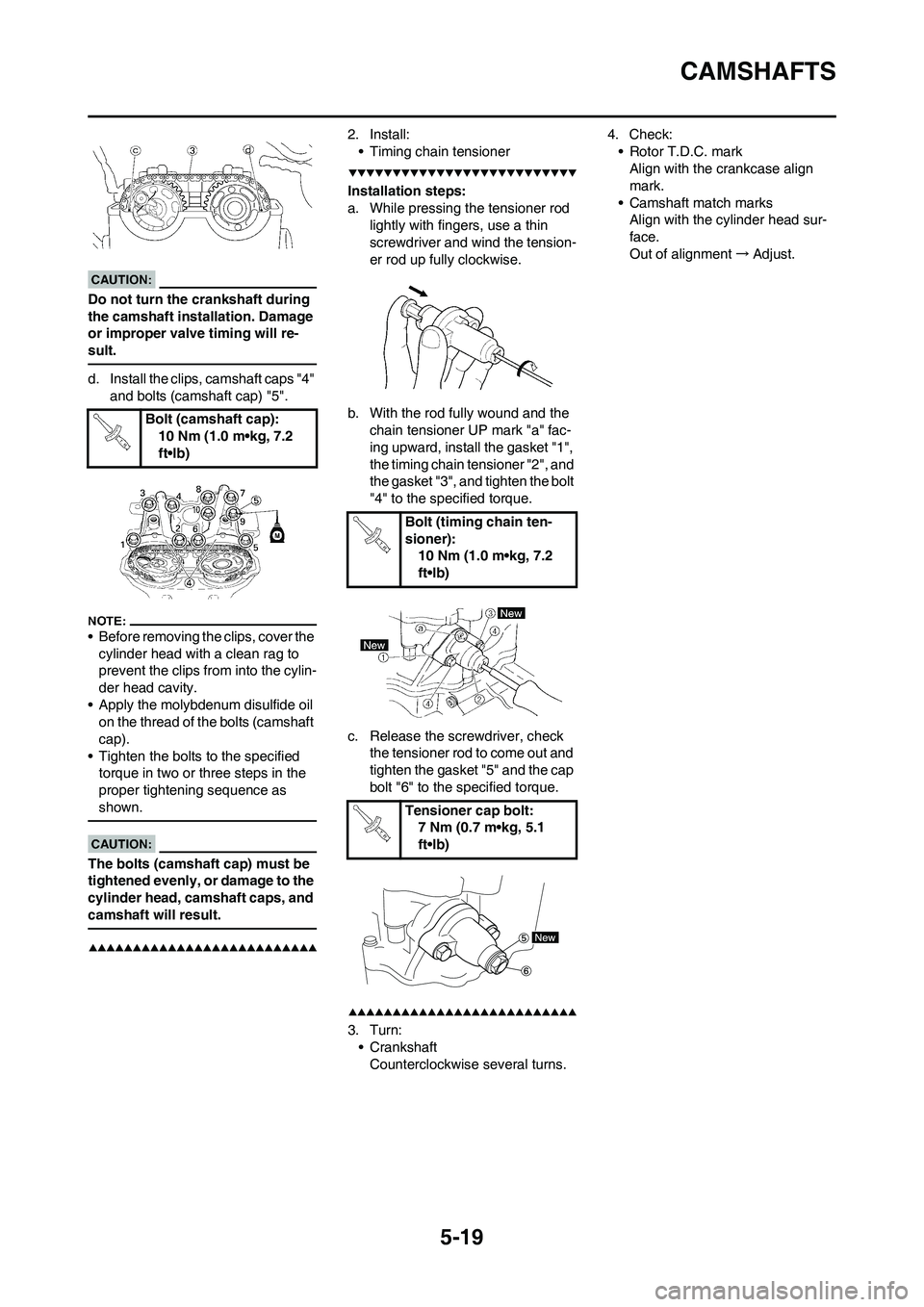
d. Install the clips, camshaft caps "4"
and bolts (camshaft cap) "5".
• Before removing the clips, cover the
cylinder head with a clean rag to
prevent the clips from into the cylin-
der head cavity.
• Apply the molybdenum disulfide oil
on the thread of the bolts (camshaft
cap).
• Tighten the bolts to the specified
torque in two or three steps in the
proper tightening sequence as
shown.
The bolts (camshaft cap) must be
tightened evenly, or damage to the
cylinder head, camshaft caps, and
camshaft will result.
2. Install:
• Timing chain tensioner
Installation steps:
a. While pressing the tensioner rod
lightly with fingers, use a thin
screwdriver and wind the tension-
er rod up fully clockwise.
b. With the rod fully wound and the
chain tensioner UP mark "a" fac-
ing upward, install the gasket "1",
the timing chain tensioner "2", and
the gasket "3", and tighten the bolt
"4" to the specified torque.
c. Release the screwdriver, check
the tensioner rod to come out and
tighten the gasket "5" and the cap
bolt "6" to the specified torque.
3. Turn:
• Crankshaft
Counterclockwise several turns.4. Check:
• Rotor T.D.C. mark
Align with the crankcase align
mark.
• Camshaft match marks
Align with the cylinder head sur-
face.
Out of alignment→Adjust.
Bolt (camshaft cap):
10 Nm (1.0 m•kg, 7.2
ft•lb)
Bolt (timing chain ten-
sioner):
10 Nm (1.0 m•kg, 7.2
ft•lb)
Tensioner cap bolt:
7 Nm (0.7 m•kg, 5.1
ft•lb)
Page 116 of 224
5-20
CYLINDER HEAD
CYLINDER HEAD
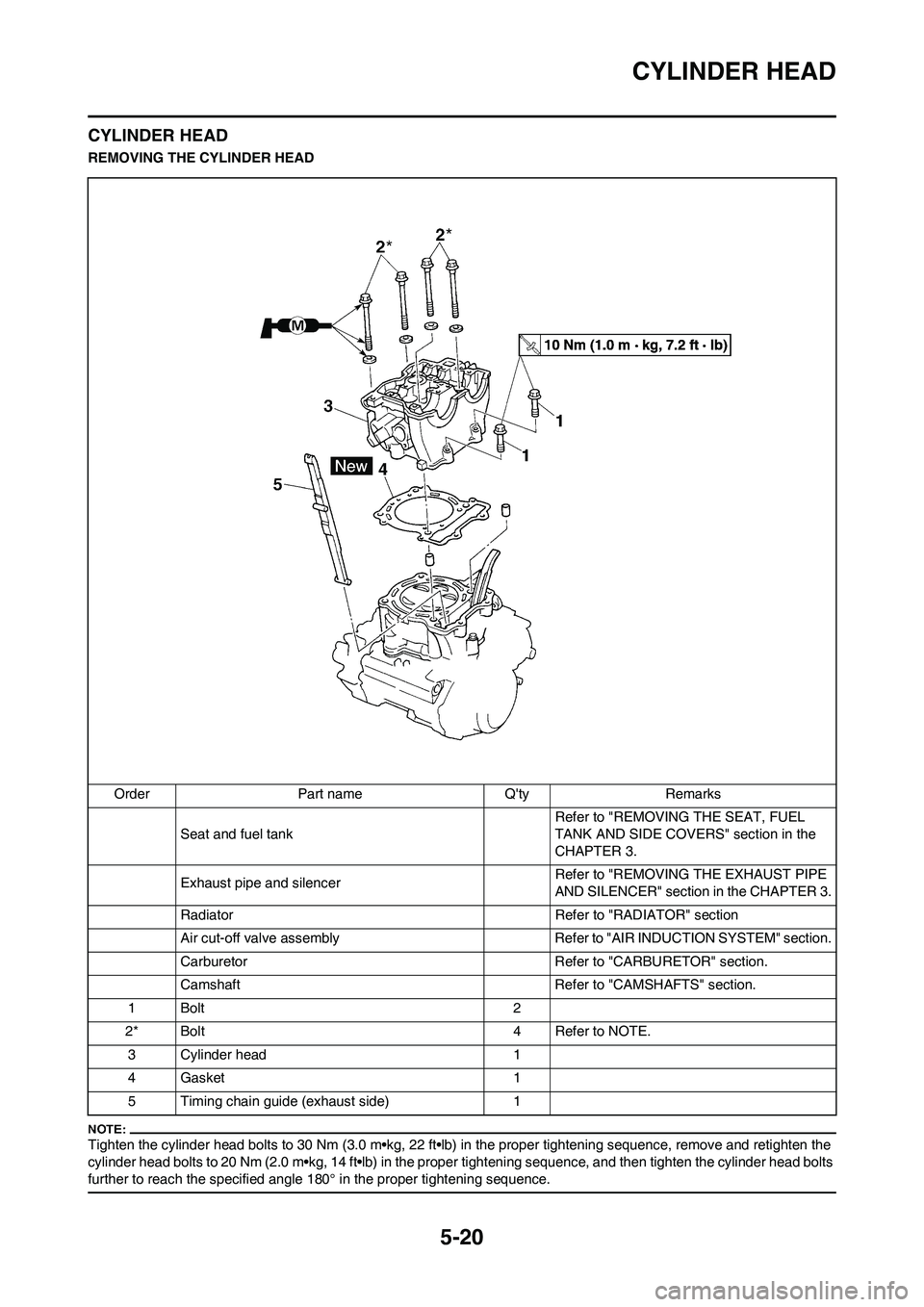
REMOVING THE CYLINDER HEAD
Tighten the cylinder head bolts to 30 Nm (3.0 m•kg, 22 ft•lb) in the proper tightening sequence, remove and retighten the
cylinder head bolts to 20 Nm (2.0 m•kg, 14 ft•lb) in the proper tightening sequence, and then tighten the cylinder head bolts
further to reach the specified angle 180° in the proper tightening sequence.
Order Part name Q'ty Remarks
Seat and fuel tank Refer to "REMOVING THE SEAT, FUEL
TANK AND SIDE COVERS" section in the
CHAPTER 3.
Exhaust pipe and silencerRefer to "REMOVING THE EXHAUST PIPE
AND SILENCER" section in the CHAPTER 3.
Radiator Refer to "RADIATOR" section
Air cut-off valve assembly Refer to "AIR INDUCTION SYSTEM" section.
Carburetor Refer to "CARBURETOR" section.
Camshaft Refer to "CAMSHAFTS" section.
1Bolt 2
2* Bolt 4 Refer to NOTE.
3 Cylinder head 1
4 Gasket 1
5 Timing chain guide (exhaust side) 1
Page 117 of 224

5-21
CYLINDER HEAD
CHECKING THE CYLINDER HEAD
1. Eliminate:
• Carbon deposits (from the com-
bustion chambers)
Use a rounded scraper.
Do not use a sharp instrument to
avoid damaging or scratching:
• Spark plug threads
• Valve seats
2. Inspect:
• Cylinder head
Scratches/damage→Replace.
3. Measure:
• Cylinder head warpage
Out of specification→Resurface.
Warpage measurement and resur-
facing steps:
a. Place a straightedge and a feeler
gauge across the cylinder head.
b. Use a feeler gauge to measure
the warpage.
c. If the warpage is out of specifica-
tion, resurface the cylinder head.
d. Place a 400–600 grit wet sandpa-
per on the surface plate, and re-
surface the head using a figure-
eight sanding pattern.
To ensure an even surface rotate the
cylinder head several times.
INSTALLING THE CYLINDER
HEAD
1. Install:
• Timing chain guide (exhaust side)
"1"
• Dowel pin "2"
• Cylinder head gasket "3" • Cylinder head "4"
While pulling up the timing chain, in-
stall the timing chain guide (exhaust
side) and cylinder head.
2. Install:
• Washer "1"
• Bolts "2"
Installation steps:
Tighten the cylinder head using
the rotation angle procedure to ob-
tain uniform tightening torque.
a. Wash the threads and contact
surfaces of the bolts, the contact
surfaces of the plain washers, the
contact surface of the cylinder
head, and the threads of the
crankcase.
b. Apply the molybdenum disulfide
grease on the threads and con-
tact surfaces of the bolts and on
both contact surfaces of the plain
washers.
c. Install the plain washers and
bolts.
d. Tighten the bolts to the specified
torque in two or three steps in the
proper tightening sequence as
shown.e. Remove the bolts.
f. Again apply the molybdenum dis-
ulfide grease on the threads and
contact surfaces of the bolts and
on both contact surfaces of the
plain washers.
g. Retighten the bolts.
Tighten the bolts to the specified
torque in two or three steps in the
proper tightening sequence as
shown.
h. Put a mark on the corner "1" of the
bolt (cylinder head) and the cylin-
der head "2" as shown.
Tighten the bolts 90° in each of the
two steps to reach the specified angle
of 180° in the proper tightening se-
quence as shown.
Cylinder head warpage:
Less than 0.05 mm
(0.002 in)
Bolts (cylinder head):
1st:
30 Nm (3.0 m•kg, 22
ft•lb)
Bolts (cylinder head):
2nd:
20 Nm (2.0 m•kg, 14
ft•lb)
Bolts (cylinder head):
Final:
Specified angle 180°
Page 118 of 224
5-22
CYLINDER HEAD
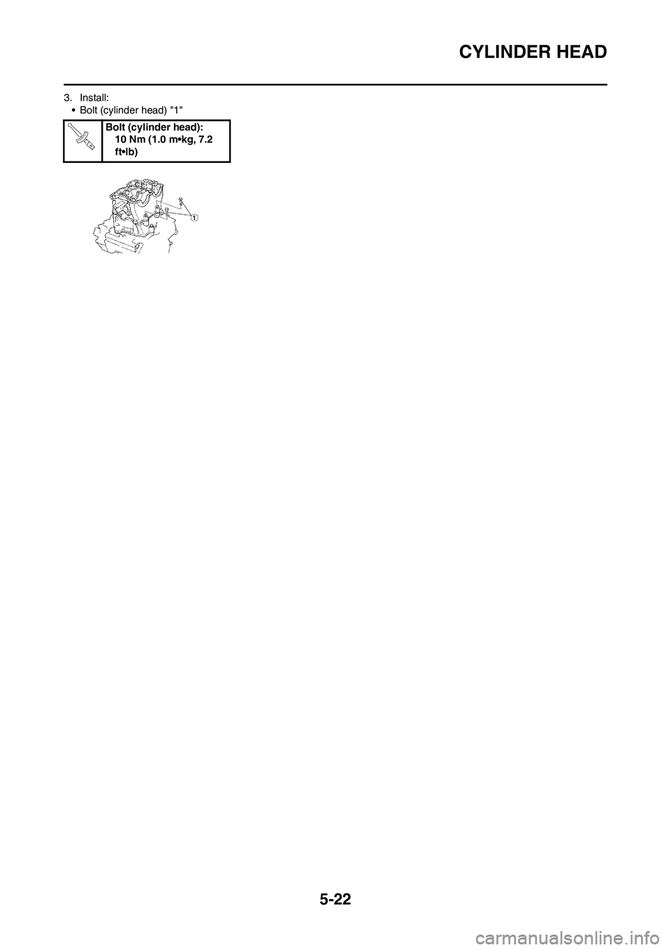
3. Install:
• Bolt (cylinder head) "1"
Bolt (cylinder head):
10 Nm (1.0 m•kg, 7.2
ft•lb)
Page 119 of 224
5-23
VALVES AND VALVE SPRINGS
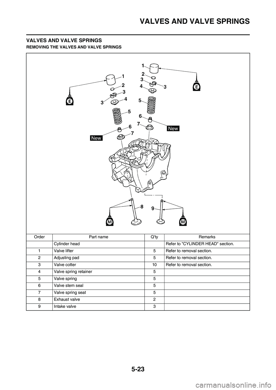
VALVES AND VALVE SPRINGS
REMOVING THE VALVES AND VALVE SPRINGS
Order Part name Q'ty Remarks
Cylinder head Refer to "CYLINDER HEAD" section.
1 Valve lifter 5 Refer to removal section.
2 Adjusting pad 5 Refer to removal section.
3 Valve cotter 10 Refer to removal section.
4 Valve spring retainer 5
5 Valve spring 5
6 Valve stem seal 5
7 Valve spring seat 5
8 Exhaust valve 2
9 Intake valve 3
Page 120 of 224
5-24
VALVES AND VALVE SPRINGS
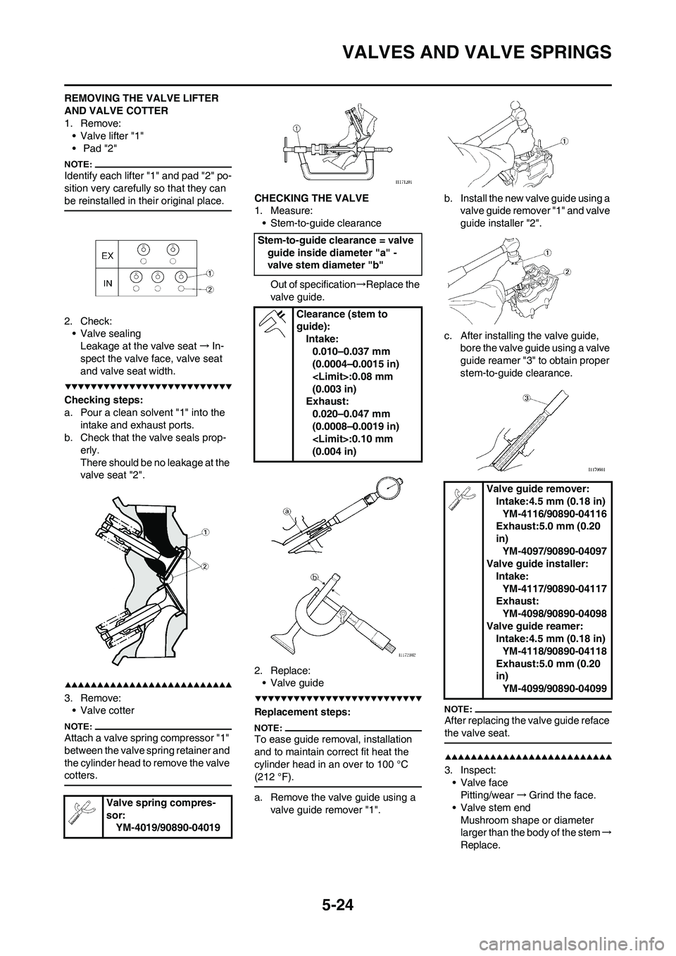
REMOVING THE VALVE LIFTER
AND VALVE COTTER
1. Remove:
• Valve lifter "1"
• Pad "2"
Identify each lifter "1" and pad "2" po-
sition very carefully so that they can
be reinstalled in their original place.
2. Check:
• Valve sealing
Leakage at the valve seat→In-
spect the valve face, valve seat
and valve seat width.
Checking steps:
a. Pour a clean solvent "1" into the
intake and exhaust ports.
b. Check that the valve seals prop-
erly.
There should be no leakage at the
valve seat "2".
3. Remove:
• Valve cotter
Attach a valve spring compressor "1"
between the valve spring retainer and
the cylinder head to remove the valve
cotters.
CHECKING THE VALVE
1. Measure:
• Stem-to-guide clearance
Out of specification→Replace the
valve guide.
2. Replace:
• Valve guide
Replacement steps:
To ease guide removal, installation
and to maintain correct fit heat the
cylinder head in an over to 100 °C
(212 °F).
a. Remove the valve guide using a
valve guide remover "1".b. Install the new valve guide using a
valve guide remover "1" and valve
guide installer "2".
c. After installing the valve guide,
bore the valve guide using a valve
guide reamer "3" to obtain proper
stem-to-guide clearance.
After replacing the valve guide reface
the valve seat.
3. Inspect:
• Valve face
Pitting/wear→Grind the face.
• Valve stem end
Mushroom shape or diameter
larger than the body of the stem→
Replace. Valve spring compres-
sor:
YM-4019/90890-04019
Stem-to-guide clearance = valve
guide inside diameter "a" -
valve stem diameter "b"
Clearance (stem to
guide):
Intake:
0.010–0.037 mm
(0.0004–0.0015 in)
(0.003 in)
Exhaust:
0.020–0.047 mm
(0.0008–0.0019 in)
(0.004 in)
Valve guide remover:
Intake:4.5 mm (0.18 in)
YM-4116/90890-04116
Exhaust:5.0 mm (0.20
in)
YM-4097/90890-04097
Valve guide installer:
Intake:
YM-4117/90890-04117
Exhaust:
YM-4098/90890-04098
Valve guide reamer:
Intake:4.5 mm (0.18 in)
YM-4118/90890-04118
Exhaust:5.0 mm (0.20
in)
YM-4099/90890-04099