engine YAMAHA WR 450F 2008 Owner's Manual
[x] Cancel search | Manufacturer: YAMAHA, Model Year: 2008, Model line: WR 450F, Model: YAMAHA WR 450F 2008Pages: 224, PDF Size: 13.7 MB
Page 45 of 224
2-18
TIGHTENING TORQUES
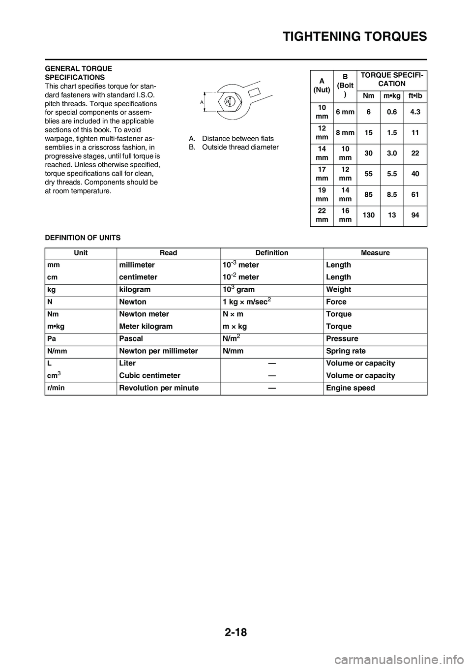
GENERAL TORQUE
SPECIFICATIONS
This chart specifies torque for stan-
dard fasteners with standard I.S.O.
pitch threads. Torque specifications
for special components or assem-
blies are included in the applicable
sections of this book. To avoid
warpage, tighten multi-fastener as-
semblies in a crisscross fashion, in
progressive stages, until full torque is
reached. Unless otherwise specified,
torque specifications call for clean,
dry threads. Components should be
at room temperature.A. Distance between flats
B. Outside thread diameter
DEFINITION OF UNITS
A
(Nut)B
(Bolt
)TORQUE SPECIFI-
CATION
Nm m•kg ft•lb
10
mm6 mm 6 0.6 4.3
12
mm8 mm 15 1.5 11
14
mm10
mm30 3.0 22
17
mm12
mm55 5.5 40
19
mm14
mm85 8.5 61
22
mm16
mm130 13 94
Unit Read Definition Measure
mm
millimeter 10-3 meter Length
cmcentimeter 10-2 meter Length
kgkilogram 103 gram Weight
NNewton 1 kg × m/sec2Force
NmNewton meter N × m Torque
m•kgMeter kilogram m × kg Torque
PaPascal N/m2Pressure
N/mmNewton per millimeter N/mm Spring rate
LLiter — Volume or capacity
cm3Cubic centimeter — Volume or capacity
r/minRevolution per minute — Engine speed
Page 49 of 224

2-22
CABLE ROUTING DIAGRAM
C. Fasten the diode (at the mark-
ing), throttle cable and hot start-
er cable onto the frame. Locate
the clamp end facing toward the
lower right of the frame and with
the tie end facing downward.
D. Fasten the wire harness, throttle
position sensor lead and clutch
cable onto the frame. Pass the
clamp through the hole in the
stay (air cut-off valve). Locate
the clamp end facing toward the
lower side of the frame and cut
off the tie end.
E. Fasten the throttle position sen-
sor lead onto the frame. Locate
the clamp end facing toward the
lower side of the frame and cut
off the tie end.
F. Pass the carburetor breather
hoses, carburetor overflow hose
and catch tank breather hose
between the connecting rod and
cross tube (frame).
G. Pass the neutral switch lead on
the inside of the engine bracket.
H. Fasten the neutral switch lead
and AC magneto lead onto the
frame. Locate the clamp end
facing toward the outside of the
frame and tie end facing toward
the rear of the frame.
I. Fasten the AC magneto lead
and neutral switch lead onto the
frame. Locate the clamp end
facing toward the rear of the
frame and cut off the tie end.
J. Pass the neutral switch lead and
AC magneto lead on the inside
of the wire harness.
K. Fasten the AC magneto lead
and neutral switch lead onto the
frame.
L. Pass the wire harness through
the cable guide.
M. Locate the couplers in the frame
recess.
N. Pass the carburetor breather
hoses, carburetor overflow hose
and catch tank breather hose so
that the hoses do not contact the
rear shock absorber.
O. Secure the coupler by pushing it
into the hole in the headlight
unit.
Page 52 of 224

2-25
CABLE ROUTING DIAGRAM
1. Clamp
2. Positive battery lead
3. Battery
4. Negative battery lead
5. Taillight coupler
6. CDI unit coupler (6-pin)
7. CDI unit coupler (3-pin)
8. CDI unit coupler (6-pin)A. Fasten the wire harness to the
upper engine bracket (left side).
Locate the clamp end facing to-
ward the upper side of the frame
with the tie end cut off on the in-
side of the frame.B. Fasten the wire harness to the
upper engine bracket (left side).
Locate the clamp end facing to-
ward the upper side of the frame
with the tie end cut off on the in-
side of the frame. Clamp the
wire harness at the marking.
C. Pass the starter motor lead
through the hole in the relay
holder.
D. Fit the cover securely.
Page 54 of 224

2-27
CABLE ROUTING DIAGRAM
1. Throttle cable
2. Clamp
3. Brake hose
4. Clutch cable
5. Hose guide
6. Main switch coupler
7. Wire harness
8. Headlight coupler
9. Hot starter cable
10. Multi-function display bracket11. Main switch
12. Upper bracket
13. Clutch switch coupler
14. Engine stop switch coupler
15. Multi-function display coupler
16. Start switch coupler
17. Speed sensor coupler
18. Speed sensor leadA. Fasten the start switch lead to
the handlebar with the plastic
bands.
B. Fasten the engine stop switch
lead and clutch switch lead to
the handlebar with the plastic
bands.
C. Pass the brake hose through
the hose guides.
Page 56 of 224
3-1
MAINTENANCE INTERVALS
REGULAR INSPECTION AND ADJUSTMENTS
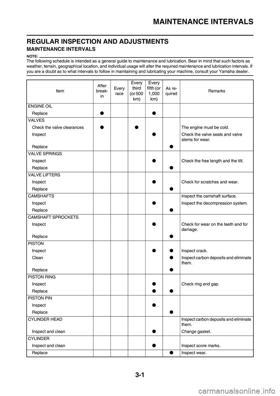
MAINTENANCE INTERVALS
The following schedule is intended as a general guide to maintenance and lubrication. Bear in mind that such factors as
weather, terrain, geographical location, and individual usage will alter the required maintenance and lubrication intervals. If
you are a doubt as to what intervals to follow in maintaining and lubricating your machine, consult your Yamaha dealer.
ItemAfter
break-
inEvery
race
Every
third
(or 500
km)Every
fifth (or
1,000
km)
As re-
quiredRemarks
ENGINE OIL
Replace●●
VALVES
Check the valve clearances●●The engine must be cold.
Inspect●Check the valve seats and valve
stems for wear.
Replace●
VALVE SPRINGS
Inspect●Check the free length and the tilt.
Replace●
VALVE LIFTERS
Inspect●Check for scratches and wear.
Replace●
CAMSHAFTS Inspect the camshaft surface.
Inspect●Inspect the decompression system.
Replace●
CAMSHAFT SPROCKETS
Inspect●Check for wear on the teeth and for
damage.
Replace●
PISTON
Inspect●●Inspect crack.
Clean●Inspect carbon deposits and eliminate
them.
Replace●
PISTON RING
Inspect●Check ring end gap.
Replace●●
PISTON PIN
Inspect●
Replace●
CYLINDER HEAD Inspect carbon deposits and eliminate
them.
Inspect and clean●Change gasket.
CYLINDER
Inspect and clean●Inspect score marks.
Replace●Inspect wear.
Page 60 of 224
3-5
PRE-OPERATION INSPECTION AND MAINTENANCE
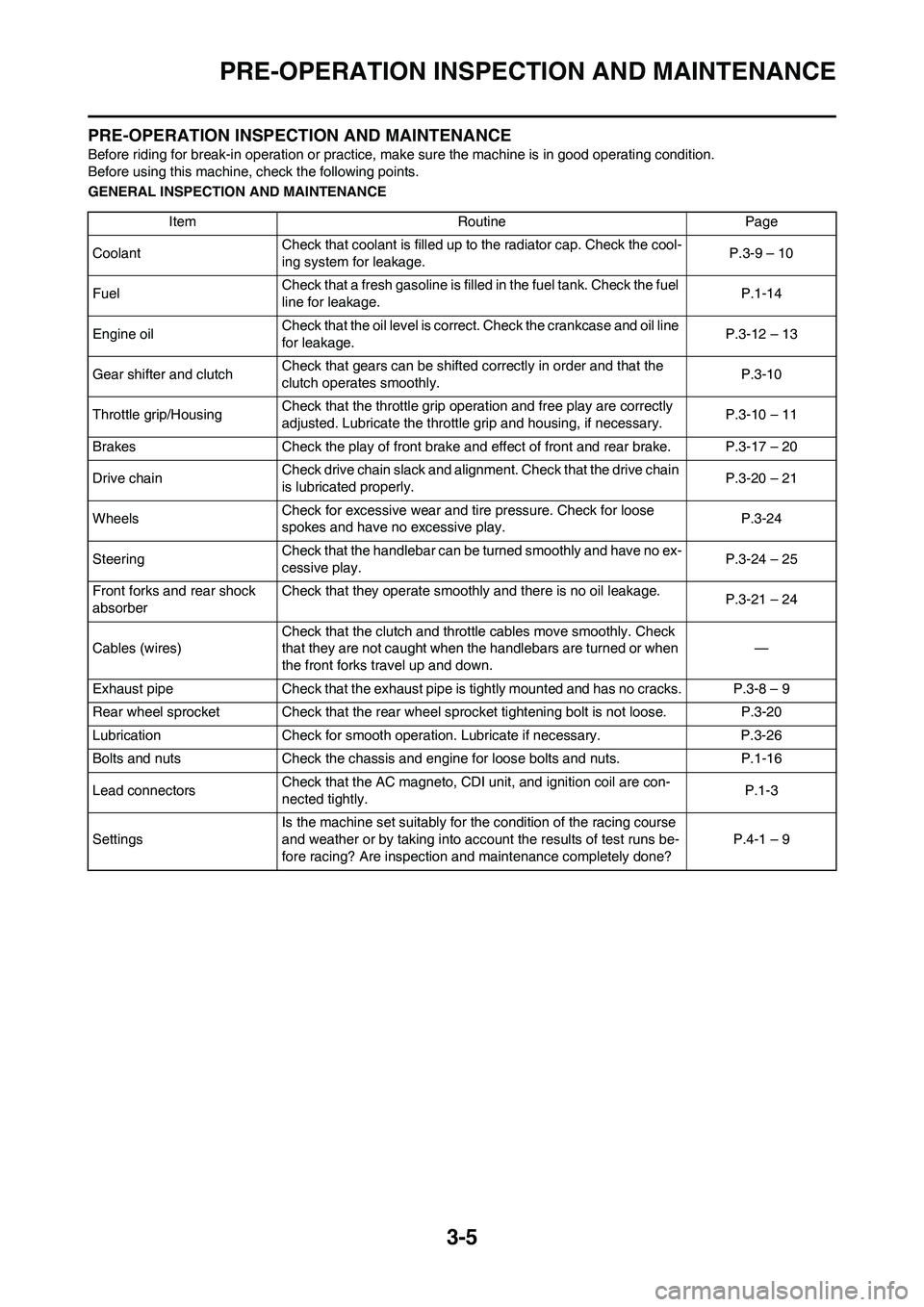
PRE-OPERATION INSPECTION AND MAINTENANCE
Before riding for break-in operation or practice, make sure the machine is in good operating condition.
Before using this machine, check the following points.
GENERAL INSPECTION AND MAINTENANCE
Item Routine Page
CoolantCheck that coolant is filled up to the radiator cap. Check the cool-
ing system for leakage.P.3-9 – 10
FuelCheck that a fresh gasoline is filled in the fuel tank. Check the fuel
line for leakage.P.1-14
Engine oilCheck that the oil level is correct. Check the crankcase and oil line
for leakage.P.3-12 – 13
Gear shifter and clutchCheck that gears can be shifted correctly in order and that the
clutch operates smoothly.P.3-10
Throttle grip/HousingCheck that the throttle grip operation and free play are correctly
adjusted. Lubricate the throttle grip and housing, if necessary.P.3-10 – 11
Brakes Check the play of front brake and effect of front and rear brake. P.3-17 – 20
Drive chainCheck drive chain slack and alignment. Check that the drive chain
is lubricated properly.P.3-20 – 21
WheelsCheck for excessive wear and tire pressure. Check for loose
spokes and have no excessive play.P.3-24
SteeringCheck that the handlebar can be turned smoothly and have no ex-
cessive play.P.3-24 – 25
Front forks and rear shock
absorberCheck that they operate smoothly and there is no oil leakage.
P.3-21 – 24
Cables (wires)Check that the clutch and throttle cables move smoothly. Check
that they are not caught when the handlebars are turned or when
the front forks travel up and down.—
Exhaust pipe Check that the exhaust pipe is tightly mounted and has no cracks. P.3-8 – 9
Rear wheel sprocket Check that the rear wheel sprocket tightening bolt is not loose. P.3-20
Lubrication Check for smooth operation. Lubricate if necessary. P.3-26
Bolts and nuts Check the chassis and engine for loose bolts and nuts. P.1-16
Lead connectorsCheck that the AC magneto, CDI unit, and ignition coil are con-
nected tightly.P.1-3
SettingsIs the machine set suitably for the condition of the racing course
and weather or by taking into account the results of test runs be-
fore racing? Are inspection and maintenance completely done?P.4-1 – 9
Page 61 of 224
3-6
ENGINE
ENGINE
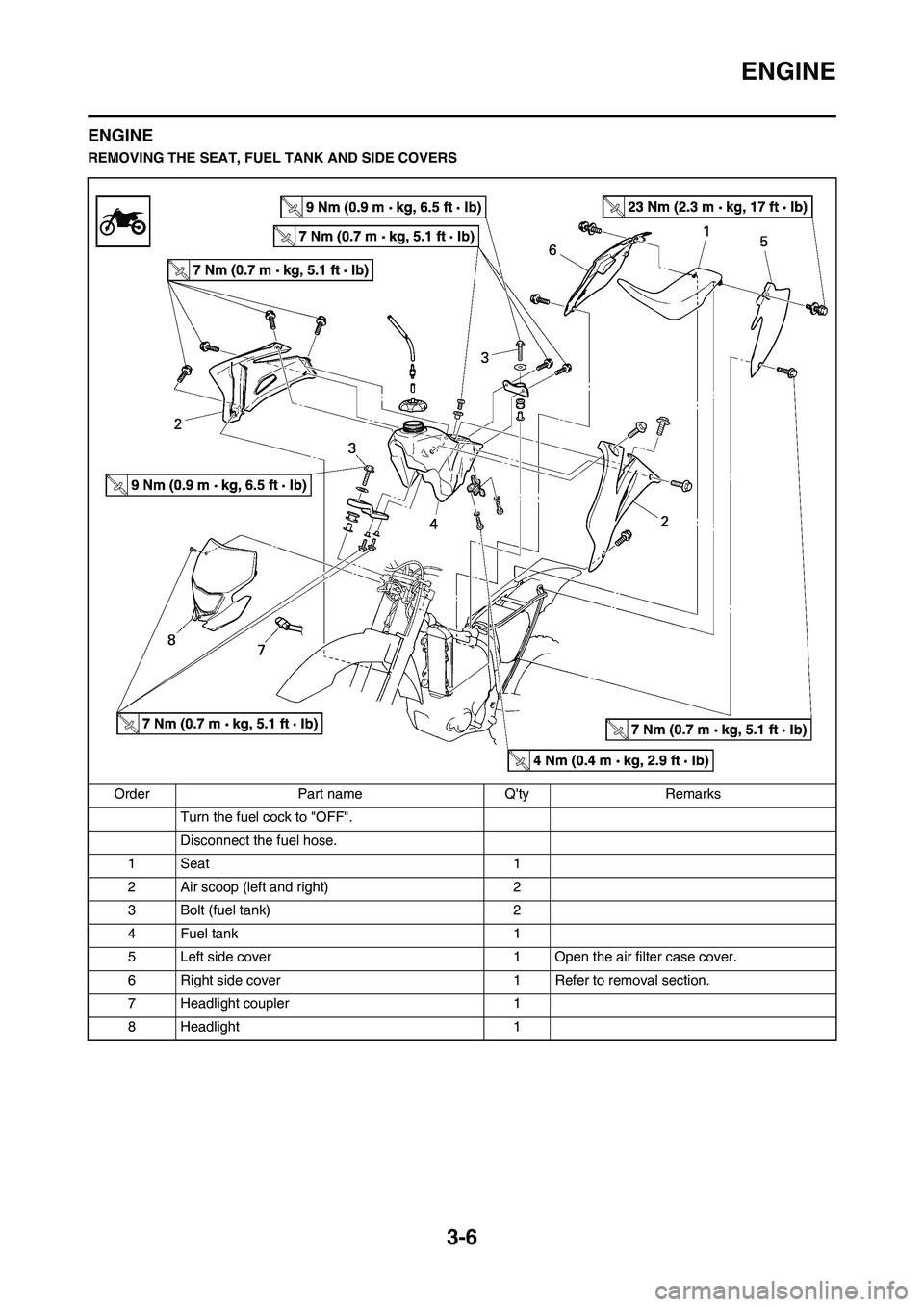
REMOVING THE SEAT, FUEL TANK AND SIDE COVERS
Order Part name Q'ty Remarks
Turn the fuel cock to "OFF".
Disconnect the fuel hose.
1Seat 1
2 Air scoop (left and right) 2
3 Bolt (fuel tank) 2
4 Fuel tank 1
5 Left side cover 1 Open the air filter case cover.
6 Right side cover 1 Refer to removal section.
7 Headlight coupler 1
8 Headlight 1
Page 62 of 224
3-7
ENGINE
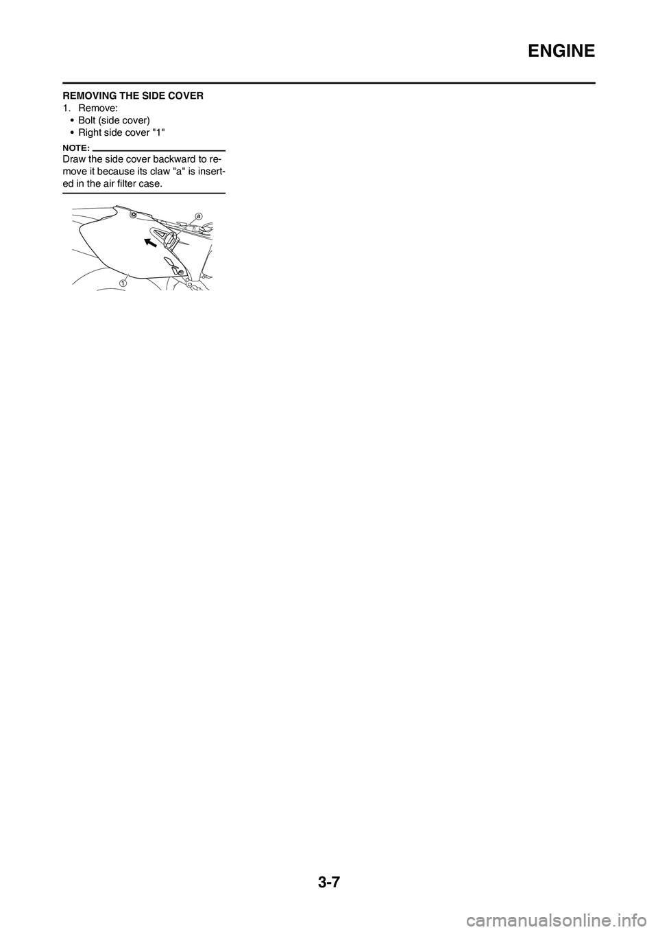
REMOVING THE SIDE COVER
1. Remove:
• Bolt (side cover)
• Right side cover "1"
Draw the side cover backward to re-
move it because its claw "a" is insert-
ed in the air filter case.
Page 63 of 224
3-8
ENGINE
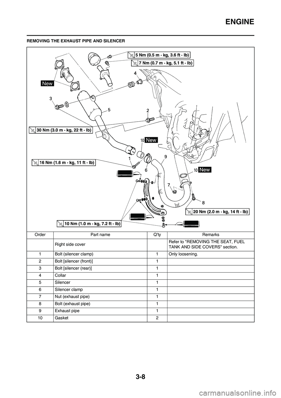
REMOVING THE EXHAUST PIPE AND SILENCER
Order Part name Q'ty Remarks
Right side coverRefer to "REMOVING THE SEAT, FUEL
TANK AND SIDE COVERS" section.
1 Bolt (silencer clamp) 1 Only loosening.
2 Bolt [silencer (front)] 1
3 Bolt [silencer (rear)] 1
4 Collar 1
5 Silencer 1
6 Silencer clamp 1
7 Nut (exhaust pipe) 1
8 Bolt (exhaust pipe) 1
9 Exhaust pipe 1
10 Gasket 2
Page 64 of 224
3-9
ENGINE
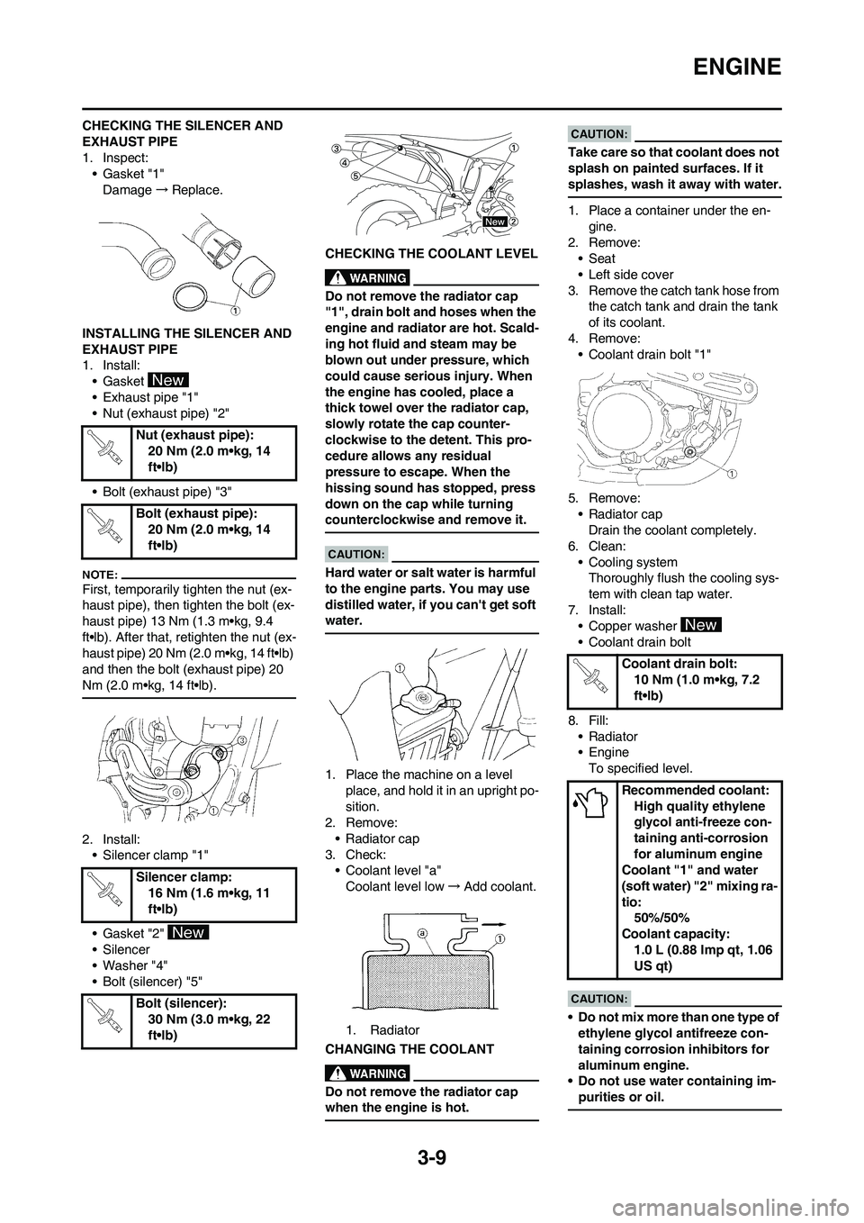
CHECKING THE SILENCER AND
EXHAUST PIPE
1. Inspect:
• Gasket "1"
Damage→Replace.
INSTALLING THE SILENCER AND
EXHAUST PIPE
1. Install:
• Gasket
• Exhaust pipe "1"
• Nut (exhaust pipe) "2"
• Bolt (exhaust pipe) "3"
First, temporarily tighten the nut (ex-
haust pipe), then tighten the bolt (ex-
haust pipe) 13 Nm (1.3 m•kg, 9.4
ft•lb). After that, retighten the nut (ex-
haust pipe) 20 Nm (2.0 m•kg, 14 ft•lb)
and then the bolt (exhaust pipe) 20
Nm (2.0 m•kg, 14 ft•lb).
2. Install:
• Silencer clamp "1"
• Gasket "2"
• Silencer
• Washer "4"
• Bolt (silencer) "5"CHECKING THE COOLANT LEVEL
Do not remove the radiator cap
"1", drain bolt and hoses when the
engine and radiator are hot. Scald-
ing hot fluid and steam may be
blown out under pressure, which
could cause serious injury. When
the engine has cooled, place a
thick towel over the radiator cap,
slowly rotate the cap counter-
clockwise to the detent. This pro-
cedure allows any residual
pressure to escape. When the
hissing sound has stopped, press
down on the cap while turning
counterclockwise and remove it.
Hard water or salt water is harmful
to the engine parts. You may use
distilled water, if you can't get soft
water.
1. Place the machine on a level
place, and hold it in an upright po-
sition.
2. Remove:
• Radiator cap
3. Check:
• Coolant level "a"
Coolant level low→Add coolant.
1. Radiator
CHANGING THE COOLANT
Do not remove the radiator cap
when the engine is hot.
Take care so that coolant does not
splash on painted surfaces. If it
splashes, wash it away with water.
1. Place a container under the en-
gine.
2. Remove:
• Seat
• Left side cover
3. Remove the catch tank hose from
the catch tank and drain the tank
of its coolant.
4. Remove:
• Coolant drain bolt "1"
5. Remove:
• Radiator cap
Drain the coolant completely.
6. Clean:
• Cooling system
Thoroughly flush the cooling sys-
tem with clean tap water.
7. Install:
• Copper washer
• Coolant drain bolt
8. Fill:
•Radiator
• Engine
To specified level.
• Do not mix more than one type of
ethylene glycol antifreeze con-
taining corrosion inhibitors for
aluminum engine.
• Do not use water containing im-
purities or oil.
Nut (exhaust pipe):
20 Nm (2.0 m•kg, 14
ft•lb)
Bolt (exhaust pipe):
20 Nm (2.0 m•kg, 14
ft•lb)
Silencer clamp:
16 Nm (1.6 m•kg, 11
ft•lb)
Bolt (silencer):
30 Nm (3.0 m•kg, 22
ft•lb)
Coolant drain bolt:
10 Nm (1.0 m•kg, 7.2
ft•lb)
Recommended coolant:
High quality ethylene
glycol anti-freeze con-
taining anti-corrosion
for aluminum engine
Coolant "1" and water
(soft water) "2" mixing ra-
tio:
50%/50%
Coolant capacity:
1.0 L (0.88 Imp qt, 1.06
US qt)