engine YAMAHA WR 450F 2016 Owners Manual
[x] Cancel search | Manufacturer: YAMAHA, Model Year: 2016, Model line: WR 450F, Model: YAMAHA WR 450F 2016Pages: 426, PDF Size: 10.86 MB
Page 282 of 426
SHIFT SHAFT
6-55
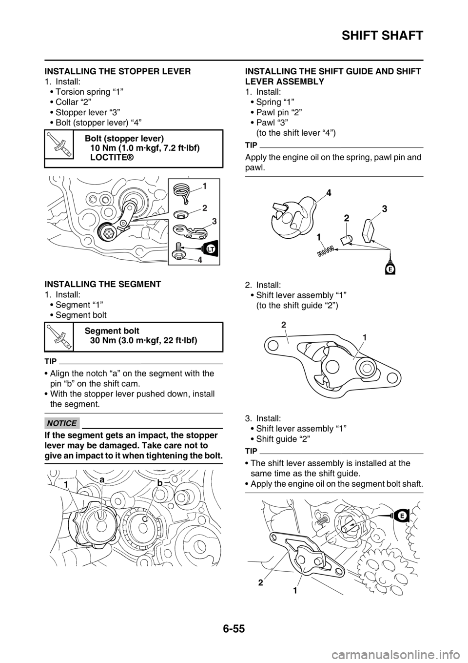
EAS2GC1293INSTALLING THE STOPPER LEVER
1. Install:• Torsion spring “1”
• Collar “2”
• Stopper lever “3”
• Bolt (stopper lever) “4”
EAS2GC1294INSTALLING THE SEGMENT
1. Install:• Segment “1”
• Segment bolt
TIP
• Align the notch “a” on the segment with the pin “b” on the shift cam.
• With the stopper lever pushed down, install
the segment.
ECA
NOTICE
If the segment gets an impact, the stopper
lever may be damaged. Take care not to
give an impact to it when tightening the bolt.
EAS2GC1295INSTALLING THE SHIFT GUIDE AND SHIFT
LEVER ASSEMBLY
1. Install: • Spring “1”
• Pawl pin “2”
•Pawl “3”(to the shift lever “4”)
TIP
Apply the engine oil on the spring, pawl pin and
pawl.
2. Install:
• Shift lever assembly “1”(to the shift guide “2”)
3. Install: • Shift lever assembly “1”
• Shift guide “2”
TIP
• The shift lever assembly is installed at the
same time as the shift guide.
• Apply the engine oil on the segment bolt shaft.
Bolt (stopper lever)
10 Nm (1.0 m·kgf, 7.2 ft·lbf)
LOCTITE®
Segment bolt 30 Nm (3.0 m·kgf, 22 ft·lbf)
T R..
2
1
3
4
LT
T R..1
2
1
2
Page 283 of 426
SHIFT SHAFT
6-56
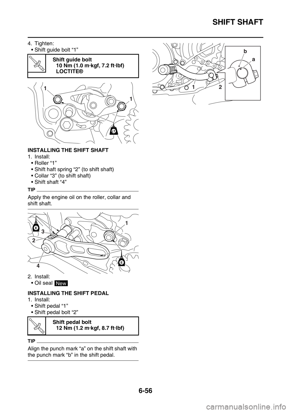
4. Tighten:• Shift guide bolt “1”
EAS2GC1296INSTALLING THE SHIFT SHAFT
1. Install:• Roller “1”
• Shift haft spring “2” (to shift shaft)
• Collar “3” (to shift shaft)
• Shift shaft “4”
TIP
Apply the engine oil on the roller, collar and
shift shaft.
2. Install:• Oil seal
EAS2GC1297INSTALLING THE SHIFT PEDAL
1. Install:• Shift pedal “1”
• Shift pedal bolt “2”
TIP
Align the punch mark “a” on the shift shaft with
the punch mark “b” in the shift pedal. Shift guide bolt
10 Nm (1.0 m·kgf, 7.2 ft·lbf)
LOCTITE®
Shift pedal bolt 12 Nm (1.2 m·kgf, 8.7 ft·lbf)
T R..
1
1
LT
E
E
1
2 3
4
New
T R..
a
12 b
Page 287 of 426
OIL PUMP AND BALANCER GEAR
6-60
3. Check:• Oil pump operationRough movement Repeat steps (1) and
(2) or replace the defective part(s).
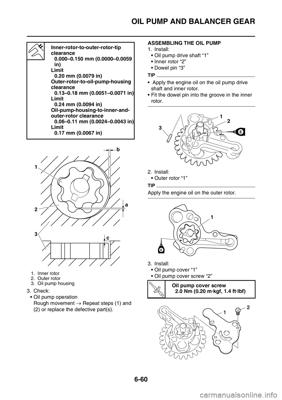
EAS2GC1303ASSEMBLING THE OIL PUMP
1. Install: • Oil pump drive shaft “1”
• Inner rotor “2”
• Dowel pin “3”
TIP
• Apply the engine oil on the oil pump drive shaft and inner rotor.
• Fit the dowel pin into the groove in the inner
rotor.
2. Install: • Outer rotor “1”
TIP
Apply the engine oil on the outer rotor.
3. Install:• Oil pump cover “1”
• Oil pump cover screw “2”
Inner-rotor-to-outer-rotor-tip
clearance
0.000–0.150 mm (0.0000–0.0059
in)
Limit 0.20 mm (0.0079 in)
Outer-rotor-to-oil-pump-housing
clearance 0.13–0.18 mm (0.0051–0.0071 in)
Limit 0.24 mm (0.0094 in)
Oil-pump-housing-to-inner-and-
outer-rotor clearance 0.06–0.11 mm (0.0024–0.0043 in)
Limit 0.17 mm (0.0067 in)
1. Inner rotor
2. Outer rotor
3. Oil pump housing
b
a
1
2
3
c
Oil pump cover screw
2.0 Nm (0.20 m·kgf, 1.4 ft·lbf)
21
3
1
E
T R..
2
1
Page 288 of 426
OIL PUMP AND BALANCER GEAR
6-61
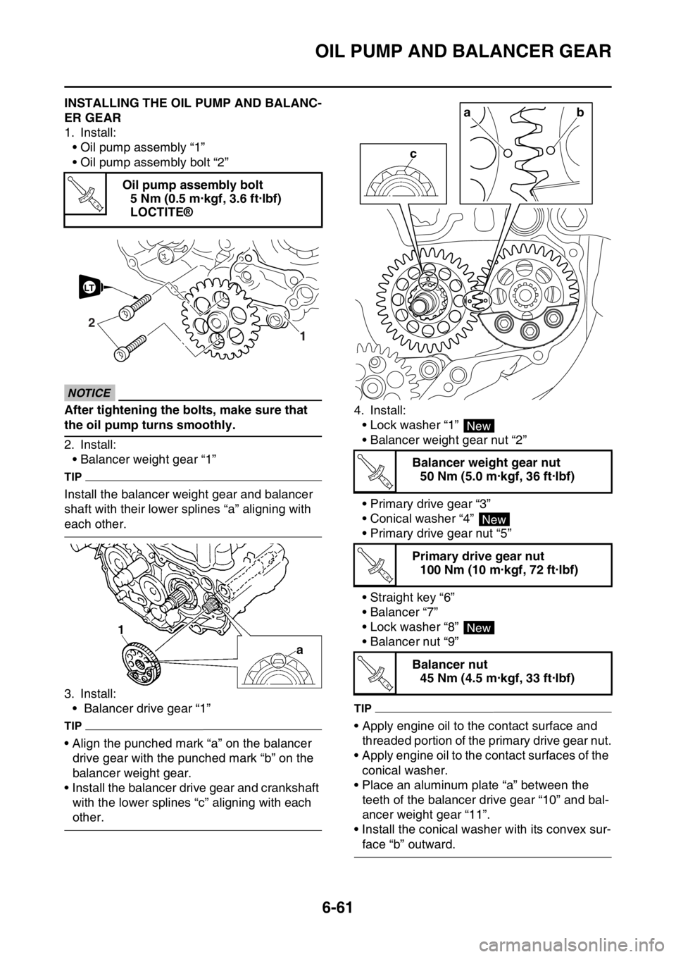
EAS2GC1304INSTALLING THE OIL PUMP AND BALANC-
ER GEAR
1. Install:• Oil pump assembly “1”
• Oil pump assembly bolt “2”
ECA1DX1023
NOTICE
After tightening the bolts, make sure that
the oil pump turns smoothly.
2. Install:• Balancer weight gear “1”
TIP
Install the balancer weight gear and balancer
shaft with their lower sp lines “a” aligning with
each other.
3. Install:
• Balancer drive gear “1”
TIP
• Align the punched mark “a” on the balancer drive gear with the punched mark “b” on the
balancer weight gear.
• Install the balancer drive gear and crankshaft with the lower splines “c” aligning with each
other. 4. Install:
• Lock washer “1”
• Balancer weight gear nut “2”
• Primary drive gear “3”
• Conical washer “4”
• Primary drive gear nut “5”
• Straight key “6”
•Balancer “7”
• Lock washer “8”
• Balancer nut “9”
TIP
• Apply engine oil to the contact surface and threaded portion of the primary drive gear nut.
• Apply engine oil to the contact surfaces of the
conical washer.
• Place an aluminum plate “a” between the teeth of the balancer drive gear “10” and bal-
ancer weight gear “11”.
• Install the conical wash er with its convex sur-
face “b” outward.
Oil pump assembly bolt
5 Nm (0.5 m·kgf, 3.6 ft·lbf)
LOCTITE®
T R..
1
2
LT
Balancer weight gear nut50 Nm (5.0 m·kgf, 36 ft·lbf)
Primary drive gear nut 100 Nm (10 m·kgf, 72 ft·lbf)
Balancer nut 45 Nm (4.5 m·kgf, 33 ft·lbf)
ba
New
T R..
New
T R..
New
T R..
Page 290 of 426
GENERATOR AND STARTER CLUTCH
6-63
EAS2GC1305
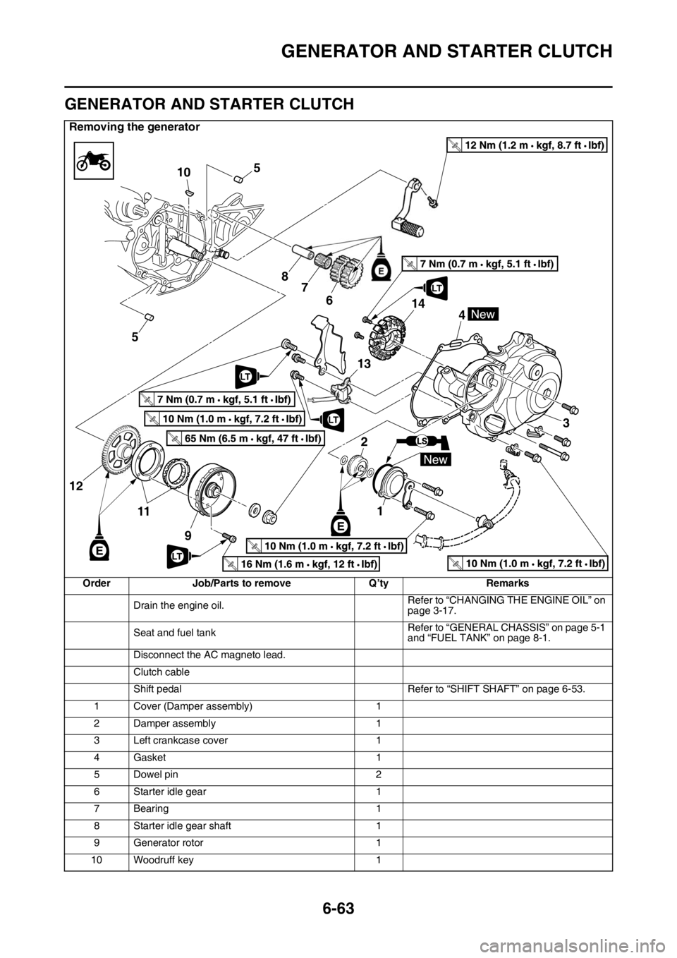
GENERATOR AND STARTER CLUTCH
Removing the generator
Order Job/Parts to remove Q’tyRemarks
Drain the engine oil. Refer to “CHANGING THE ENGINE OIL” on
page 3-17.
Seat and fuel tank Refer to “GENERAL CHASSIS” on page 5-1
and “FUEL TANK” on page 8-1.
Disconnect the AC magneto lead.
Clutch cable
Shift pedal Refer to “SHIFT SHAFT” on page 6-53.
1 Cover (Damper assembly) 1
2 Damper assembly 1
3 Left crankcase cover 1
4Gasket 1
5 Dowel pin 2
6 Starter idle gear 1
7 Bearing 1
8 Starter idle gear shaft 1
9 Generator rotor 1
10 Woodruff key 1
T R..
T R..
T R..
5
5 10
87
6
21
13 3
4
11 9
12
T R..
T R..
T R..LT
LT
T R..
T R..
14
LT
LT
Page 293 of 426
GENERATOR AND STARTER CLUTCH
6-66
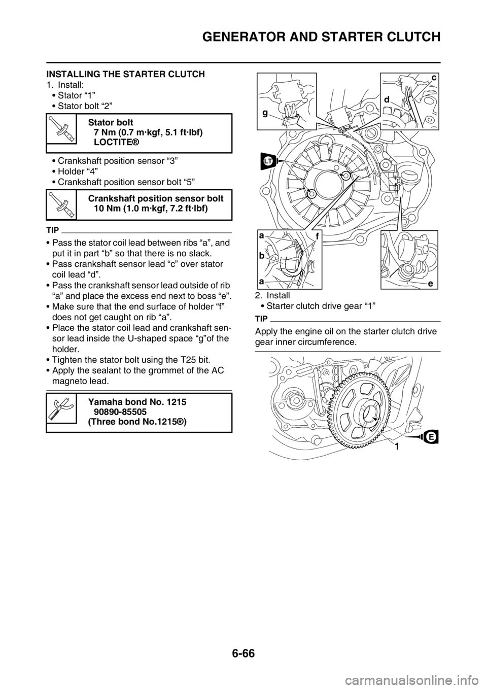
EAS2GC1308INSTALLING THE STARTER CLUTCH
1. Install:• Stator “1”
• Stator bolt “2”
• Crankshaft position sensor “3”
• Holder “4”
• Crankshaft position sensor bolt “5”
TIP
• Pass the stator coil lead between ribs “a”, and put it in part “b” so that there is no slack.
• Pass crankshaft sensor lead “c” over stator
coil lead “d”.
• Pass the crankshaft sensor lead outside of rib “a” and place the excess end next to boss “e”.
• Make sure that the end surface of holder “f” does not get caught on rib “a”.
• Place the stator coil lead and crankshaft sen-
sor lead inside the U-shaped space “g”of the
holder.
• Tighten the stator bolt using the T25 bit.
• Apply the sealant to the grommet of the AC
magneto lead. 2. Install
• Starter clutch drive gear “1”
TIP
Apply the engine oil on the starter clutch drive
gear inner circumference.
Stator bolt
7 Nm (0.7 m·kgf, 5.1 ft·lbf)
LOCTITE®
Crankshaft position sensor bolt 10 Nm (1.0 m·kgf, 7.2 ft·lbf)
Yamaha bond No. 1215 90890-85505
(Three bond No.1215®)
T R..
T R..
g
d
c
ea
a
b
f
LT
Page 294 of 426
GENERATOR AND STARTER CLUTCH
6-67
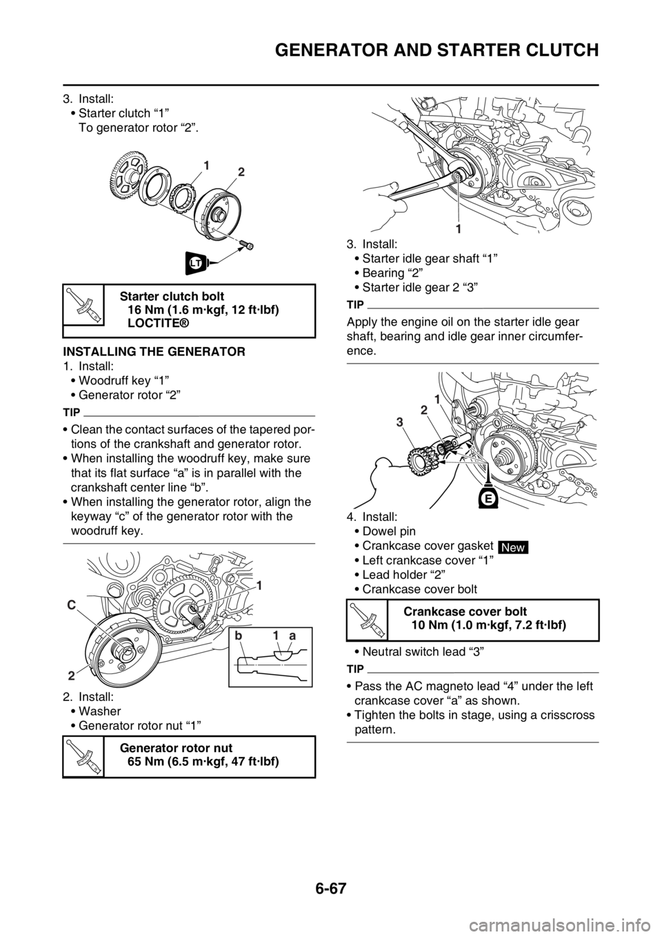
3. Install:• Starter clutch “1”To generator rotor “2”.
EAS2GC1309INSTALLING THE GENERATOR
1. Install:
• Woodruff key “1”
• Generator rotor “2”
TIP
• Clean the contact surfaces of the tapered por-tions of the crankshaft and generator rotor.
• When installing the woodruff key, make sure that its flat surface “a” is in parallel with the
crankshaft center line “b”.
• When installing the generator rotor, align the keyway “c” of the generator rotor with the
woodruff key.
2. Install: • Washer
• Generator rotor nut “1” 3. Install:
• Starter idle gear shaft “1”
• Bearing “2”
• Starter idle gear 2 “3”
TIP
Apply the engine oil on the starter idle gear
shaft, bearing and idle gear inner circumfer-
ence.
4. Install:
• Dowel pin
• Crankcase cover gasket
• Left crankcase cover “1”
• Lead holder “2”
• Crankcase cover bolt
• Neutral switch lead “3”
TIP
• Pass the AC magneto lead “4” under the left crankcase cover “a” as shown.
• Tighten the bolts in stage, using a crisscross
pattern.
Starter clutch bolt
16 Nm (1.6 m·kgf, 12 ft·lbf)
LOCTITE®
Generator rotor nut 65 Nm (6.5 m·kgf, 47 ft·lbf)
21
LT
T R..
2
C
1 1
1a
b
T R..
Crankcase cover bolt
10 Nm (1.0 m·kgf, 7.2 ft·lbf)
1
1
2 1
2
3
New
T R..
Page 295 of 426
GENERATOR AND STARTER CLUTCH
6-68
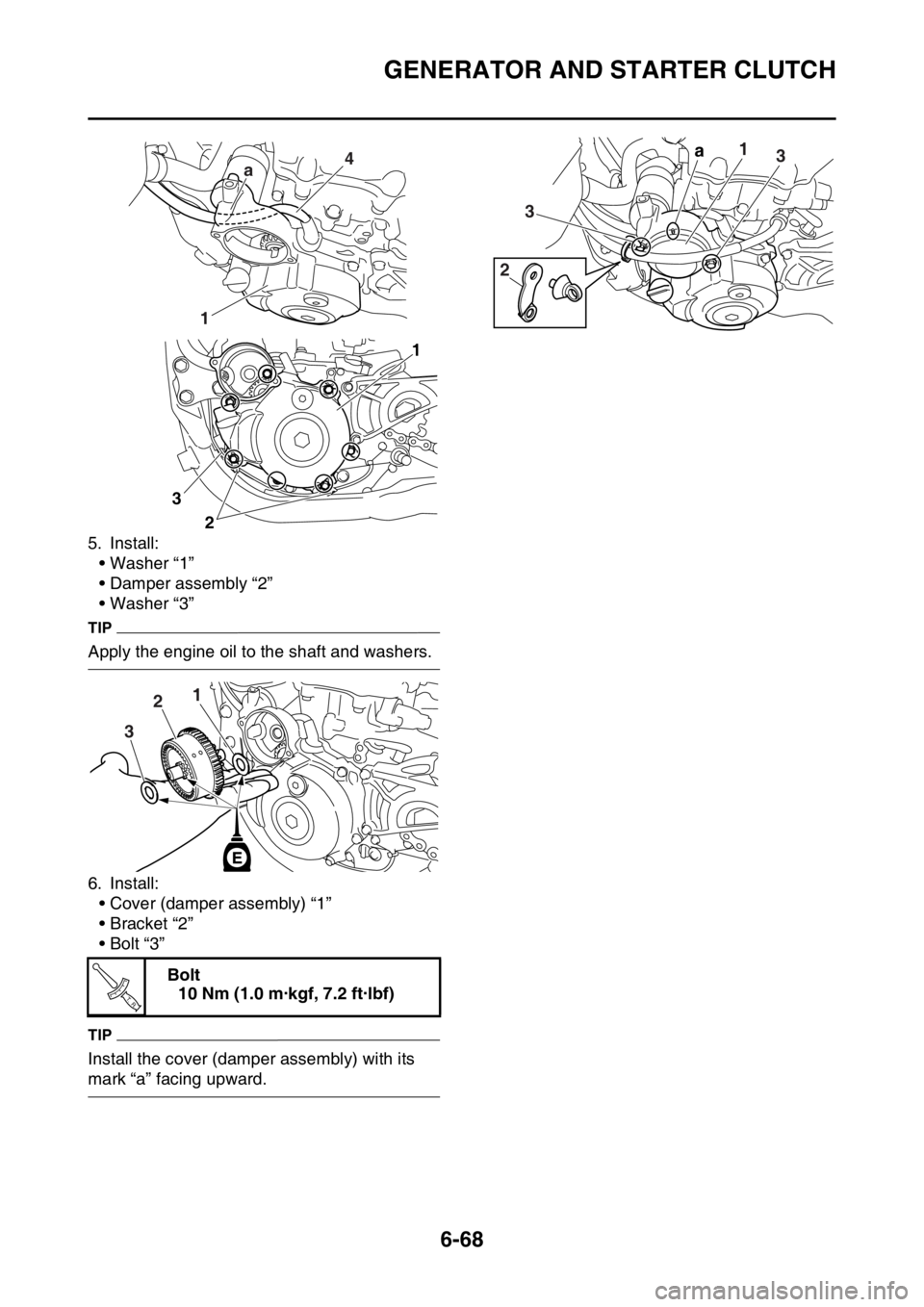
5. Install:• Washer “1”
• Damper assembly “2”
• Washer “3”
TIP
Apply the engine oil to the shaft and washers.
6. Install:• Cover (damper assembly) “1”
• Bracket “2”
•Bolt “3”
TIP
Install the cover (damper assembly) with its
mark “a” facing upward. Bolt
10 Nm (1.0 m·kgf, 7.2 ft·lbf)
4
1 a
1
2
3
2
1
2
3
T R..
1a3
3
2
Page 296 of 426
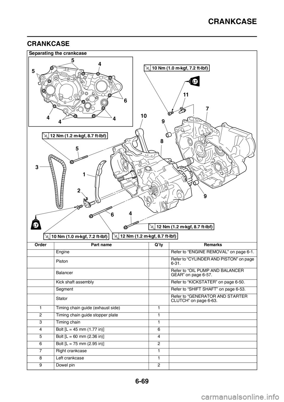
CRANKCASE
6-69
EAS2GC1310
CRANKCASE
Separating the crankcase
OrderPart name Q’tyRemarks
Engine Refer to “ENGINE REMOVAL” on page 6-1.
Piston Refer to “CYLINDER AND PISTON” on page
6-31.
Balancer Refer to “OIL PUMP AND BALANCER
GEAR” on page 6-57.
Kick shaft assembly Refer to “KICKSTATER” on page 6-50.
Segment Refer to “SHIFT SHAFT” on page 6-53.
Stator Refer to “GENERATOR AND STARTER
CLUTCH” on page 6-63.
1 Timing chain guide (exhaust side) 1
2 Timing chain guide stopper plate 1
3 Timing chain 1
4 Bolt [L = 45 mm (1.77 in)] 6
5 Bolt [L = 60 mm (2.36 in)] 4
6 Bolt [L = 75 mm (2.95 in)] 2
7 Right crankcase 1
8 Left crankcase 1
9 Dowel pin 2
10 Nm (1.0 m kgf, 7.2 ft Ibf)T.R.12 Nm (1.2 m kgf, 8.7 ft Ibf)T.R.
3
1
5
2 6410
5
5
4
4 4 46
9 7
8
11
9
LT
10 Nm (1.0 m kgf, 7.2 ft Ibf)T.R.
12 Nm (1.2 m kgf, 8.7 ft Ibf)T.R.
12 Nm (1.2 m kgf, 8.7 ft Ibf)T.R.
LT
Page 299 of 426

CRANKCASE
6-72
EAS2GC1311DISASSEMBLING THE CRANKCASE
1. Separate:• Right crankcase
• Left crankcase
▼▼▼▼▼▼▼▼▼▼▼▼▼▼▼▼▼▼▼▼▼▼▼▼▼▼▼▼▼▼▼▼
a. Remove the crankcase bolts.
TIP
Loosen each bolt 1/4 of a turn at a time and af-
ter all the bolts are loosened, remove them.
b. Remove the right crankcase “1”.
TIP
• Place the crankcase with its left side down-ward and split it by inserting a screwdriver tip
into the splitting slit “a” in the crankcase.
• Lift the right crankcase horizontally while light-
ly patting the crankcase splitting slit and the
engine mounting boss using a soft hammer,
and leave the crankshaft and the transmission
with the left crankcase.
ECA33DD041
NOTICE
Use soft hammer to tap on the case half.
Tap only on reinforced portions of case. Do
not tap on gasket mating surface. Work
slowly and carefully. Make sure the case
halves separate evenly. If the cases do not
separate, check for a remaining case bolt or
fitting. Do not force. c. Remove the dowel pins and O-ring.
▲▲▲▲▲▲▲▲▲▲▲▲▲▲▲▲▲▲▲▲▲▲▲▲▲▲▲▲▲▲▲▲
EAS2GC1312REMOVING THE CRANKCASE BEARING
1. Remove:
• Bearing “1”
TIP
• Remove the bearing from the crankcase by pressing its inner race.
• Do not use the removed bearing.
EAS2GC1313CHECKING THE TIMING CHAIN, TIMING
CHAIN GUIDE, OIL STRAINER
1. Check:• Timing chainStiffness Replace the camshaft sprocket,
timing chain and crankshaft sprocket as a
set.
2. Check: • Timing chain guide
Damage/wear Replace
EAS2GC1314CHECKING THE CRANKCASE
1. Wash:
• Crankcase
TIP
• Wash the crankcase in a mild solvent.
• Remove any remaining gasket from the
crankcase mating surface.
2. Check: • CrankcaseCrack/damage Replace.
1
a