engine YAMAHA WR 450F 2016 Repair Manual
[x] Cancel search | Manufacturer: YAMAHA, Model Year: 2016, Model line: WR 450F, Model: YAMAHA WR 450F 2016Pages: 426, PDF Size: 10.86 MB
Page 136 of 426
CHASSIS
3-38
c. Turn the front fork to the right and left a few times, and make sure that the steering ro-
tates smoothly. If it does not turn smoothly,
remove the lower bracket and check the up-
per and lower bearings.
Refer to “STEERING HEAD” on page 5-53.
d. Loosen the ring nut fully turn and then tight- en it to specification with a steering nut
wrench.
EWA
WARNING
Do not overtighten the lower ring nut.
e. Check the steering head for looseness or binding by turning the front fork all the way in
both directions. If any binding is felt, remove
the lower bracket and check the upper and
lower bearings.
Refer to “STEERING HEAD” on page 5-53.
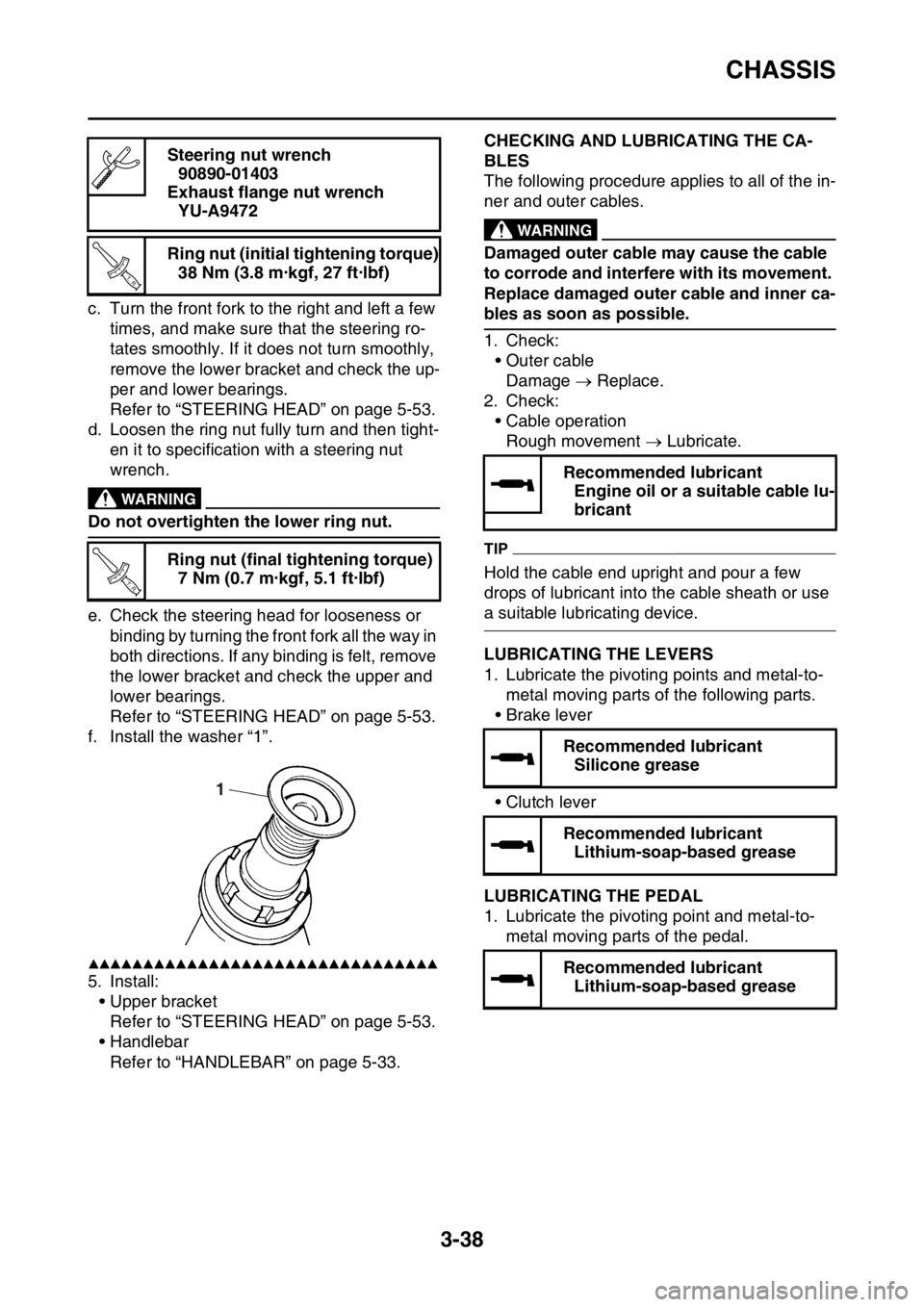
f. Install the washer “1”.
▲▲▲▲▲▲▲▲▲▲▲▲▲▲▲▲▲▲▲▲▲▲▲▲▲▲▲▲▲▲▲▲
5. Install: • Upper bracketRefer to “STEERING HEAD” on page 5-53.
• Handlebar
Refer to “HANDLEBAR” on page 5-33.
EAS2GC1124CHECKING AND LUBRICATING THE CA-
BLES
The following procedure applies to all of the in-
ner and outer cables.
EWA
WARNING
Damaged outer cable may cause the cable
to corrode and interfere with its movement.
Replace damaged outer cable and inner ca-
bles as soon as possible.
1. Check:• Outer cableDamage Replace.
2. Check: • Cable operationRough movement Lubricate.
TIP
Hold the cable end upright and pour a few
drops of lubricant into the cable sheath or use
a suitable lubricating device.
EAS2GC1125LUBRICATING THE LEVERS
1. Lubricate the pivoting points and metal-to-
metal moving parts of the following parts.
•Brake lever
• Clutch lever
EAS2GC1126LUBRICATING THE PEDAL
1. Lubricate the pivoting point and metal-to-
metal moving parts of the pedal.
Steering nut wrench
90890-01403
Exhaust flange nut wrench YU-A9472
Ring nut (initial tightening torque) 38 Nm (3.8 m·kgf, 27 ft·lbf)
Ring nut (final tightening torque) 7 Nm (0.7 m·kgf, 5.1 ft·lbf)
T R..
T R..
1
Recommended lubricantEngine oil or a suitable cable lu-
bricant
Recommended lubricant Silicone grease
Recommended lubricant Lithium-soap-based grease
Recommended lubricant Lithium-soap-based grease
Page 137 of 426
CHASSIS
3-39
EAS2GC1127LUBRICATING THE DRIVE CHAIN
The drive chain consists of many interacting
parts. If the drive chain is not maintained prop-
erly, it will wear out quickly. Therefore, the drive
chain should be serviced, especially when the
vehicle is used in dusty areas.
This vehicle has a drive chain with small rubber
O-rings between each side plate. Steam clean-
ing, high-pressure washing, certain solvents,
and the use of a coarse brush can damage
these O-rings. Therefore, use only kerosene to
clean the drive chain. Wipe the drive chain dry
and thoroughly lubricate it with engine oil or
chain lubricant that is suitable for O-ring chains.
Do not use any other lubricants on the drive
chain since they may contain solvents that
could damage the O-rings.
EAS2GC1128LUBRICATING THE SIDESTAND
Lubricate the pivoting point and metal-to-metal
moving parts of the sidestand.
EAS2GC1129CHECKING THE CHASSIS FASTENERS
Make sure that all nuts, bolts, and screws are
properly tightened.
Refer to “CHASSIS TIGHTENING TORQUES”
on page 2-17.Recommended lubricant
Chain lubricant suitable for O-
ring chains
Recommended lubricant Lithium-soap-based grease
Page 139 of 426
ELECTRICAL SYSTEM
3-41
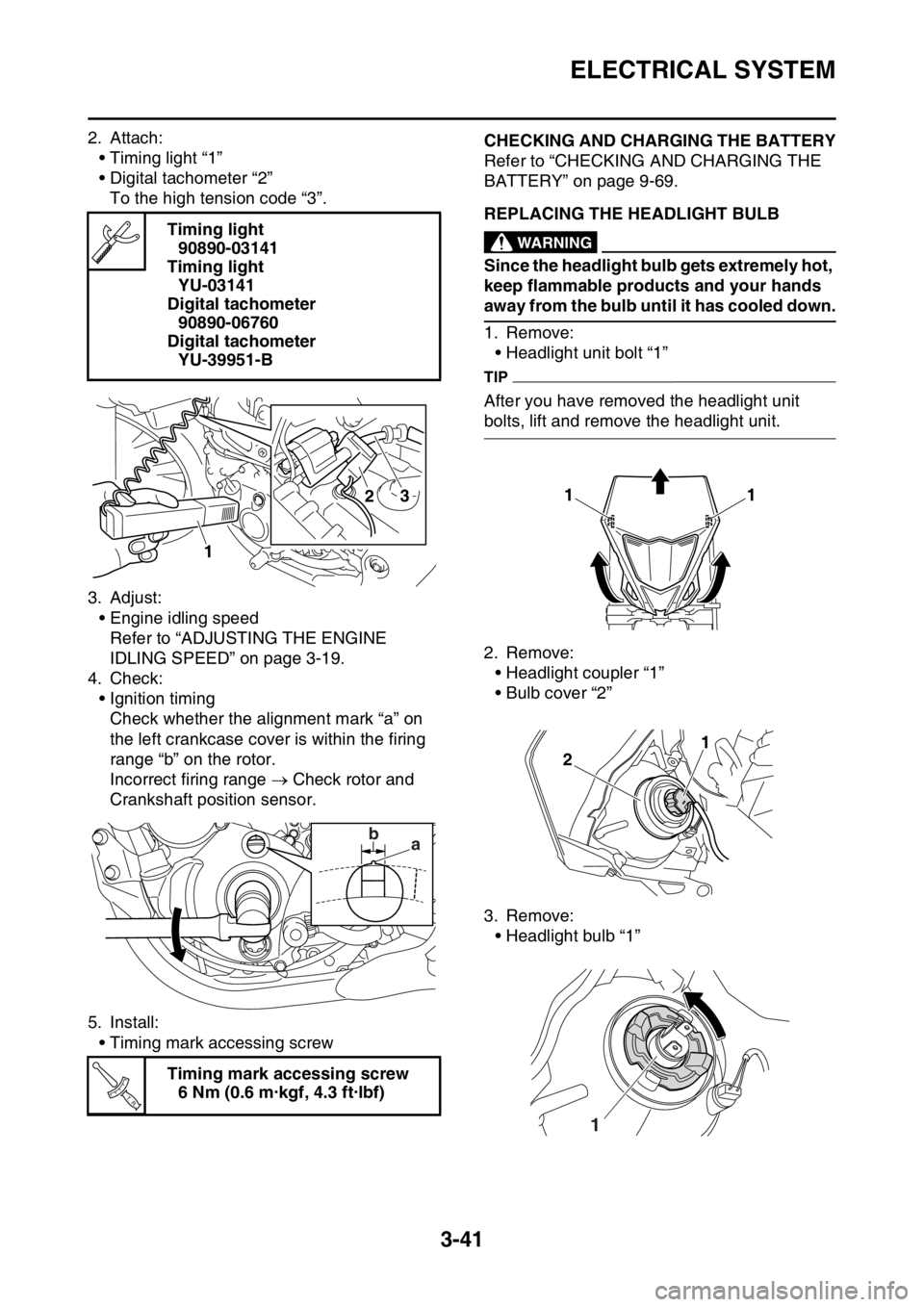
2. Attach:• Timing light “1”
• Digital tachometer “2”To the high tension code “3”.
3. Adjust: • Engine idling speedRefer to “ADJUSTING THE ENGINE
IDLING SPEED” on page 3-19.
4. Check: • Ignition timingCheck whether the alignment mark “a” on
the left crankcase cover is within the firing
range “b” on the rotor.
Incorrect firing range Check rotor and
Crankshaft position sensor.
5. Install: • Timing mark accessing screwEAS2GC1133CHECKING AND CHARGING THE BATTERY
Refer to “CHECKING AND CHARGING THE
BATTERY” on page 9-69.
EAS2GC1134REPLACING THE HEADLIGHT BULBEWA
WARNING
Since the headlight bulb gets extremely hot,
keep flammable products and your hands
away from the bulb until it has cooled down.
1. Remove:• Headlight unit bolt “1”
TIP
After you have removed the headlight unit
bolts, lift and remove the headlight unit.
2. Remove:
• Headlight coupler “1”
• Bulb cover “2”
3. Remove: • Headlight bulb “1”
Timing light
90890-03141
Timing light YU-03141
Digital tachometer 90890-06760
Digital tachometer YU-39951-B
Timing mark accessing screw 6 Nm (0.6 m·kgf, 4.3 ft·lbf)
2
1
3
ba
T R..
11
1
2
1
Page 144 of 426
CHASSIS
4-3
TIP
Generally a stiff spring gives a stiff riding feel-
ing. Rebound damping tends to become weak-
er, resulting in lack of a sense of contact with
the road surface or in a vibrating handlebar.
EAS2GC1143FRONT FORK SETTING PARTS
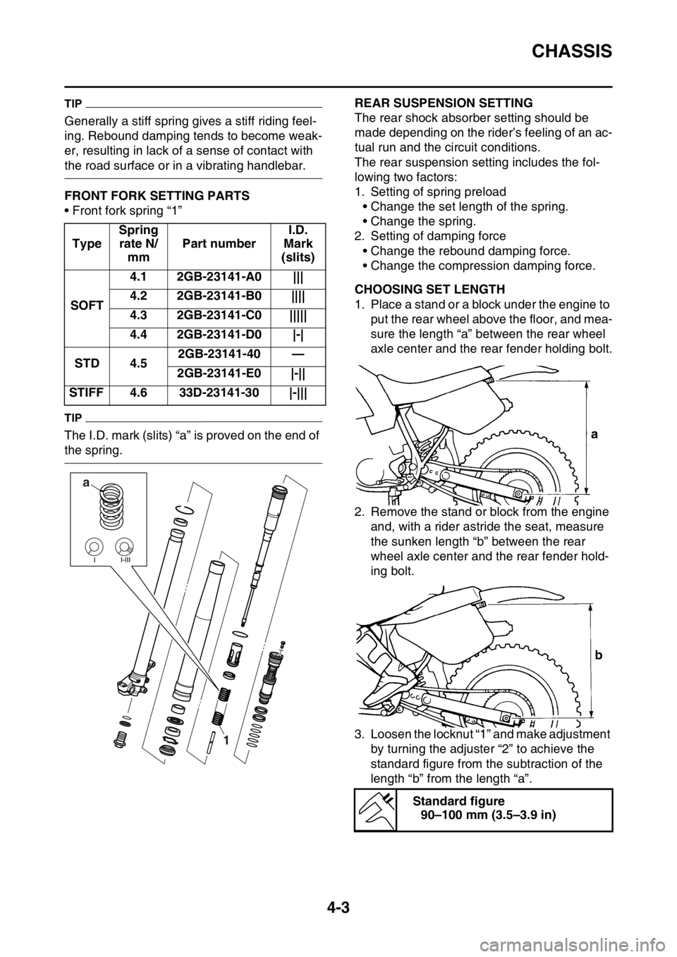
• Front fork spring “1”
TIP
The I.D. mark (slits) “a” is proved on the end of
the spring.
EAS2GC1144REAR SUSPENSION SETTING
The rear shock absorber setting should be
made depending on the rider’s feeling of an ac-
tual run and the circuit conditions.
The rear suspension setting includes the fol-
lowing two factors:
1. Setting of spring preload • Change the set length of the spring.
• Change the spring.
2. Setting of damping force
• Change the rebound damping force.
• Change the compression damping force.
EAS2GC1145CHOOSING SET LENGTH
1. Place a stand or a block under the engine to put the rear wheel above the floor, and mea-
sure the length “a” between the rear wheel
axle center and the rear fender holding bolt.
2. Remove the stand or block from the engine and, with a rider astride the seat, measure
the sunken length “b” between the rear
wheel axle center and the rear fender hold-
ing bolt.
3. Loosen the locknut “1” and make adjustment by turning the adjuster “2” to achieve the
standard figure from the subtraction of the
length “b” from the length “a”.
Type
Spring
rate N/ mm Part number I.D.
Mark
(slits)
SOFT 4.1 2GB-23141-A0 |||
4.2 2GB-23141-B0 ||||
4.3 2GB-23141-C0 |||||
4.4 2GB-23141-D0 |-|
STD 4.5 2GB-23141-40 —
2GB-23141-E0 |-||
STIFF 4.6 33D-23141-30 |-|||
a
1
Standard figure90–100 mm (3.5–3.9 in)
Page 153 of 426
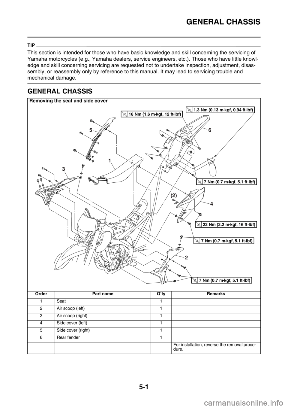
GENERAL CHASSIS
5-1
EAS2GC1150
TIP
This section is intended for those who have basic knowledge and skill concerning the servicing of
Yamaha motorcycles (e.g., Yamaha dealers, serv ice engineers, etc.). Those who have little knowl-
edge and skill concerning servicing are requested not to undertake inspection, adjustment, disas-
sembly, or reassembly only by reference to this manual. It may lead to servicing trouble and
mechanical damage.
EAS2GC1151
GENERAL CHASSIS
Removing the seat and side cover
OrderPart name Q’tyRemarks
1 Seat 1
2 Air scoop (left) 1
3 Air scoop (right) 1
4 Side cover (left) 1
5 Side cover (right) 1
6 Rear fender 1
For installation, reverse the removal proce-
dure.
4
(2)
65
1
3
2
7 Nm (0.7 m kgf, 5.1 ft Ibf)T.R.
7 Nm (0.7 m kgf, 5.1 ft Ibf)T.R.
7 Nm (0.7 m kgf, 5.1 ft Ibf)T.R.
22 Nm (2.2 m kgf, 16 ft Ibf)T.R.
1.3 Nm (0.13 m kgf, 0.94 ft Ibf)T.R.16 Nm (1.6 m kgf, 12 ft Ibf)T.R.
Page 185 of 426
HANDLEBAR
5-33
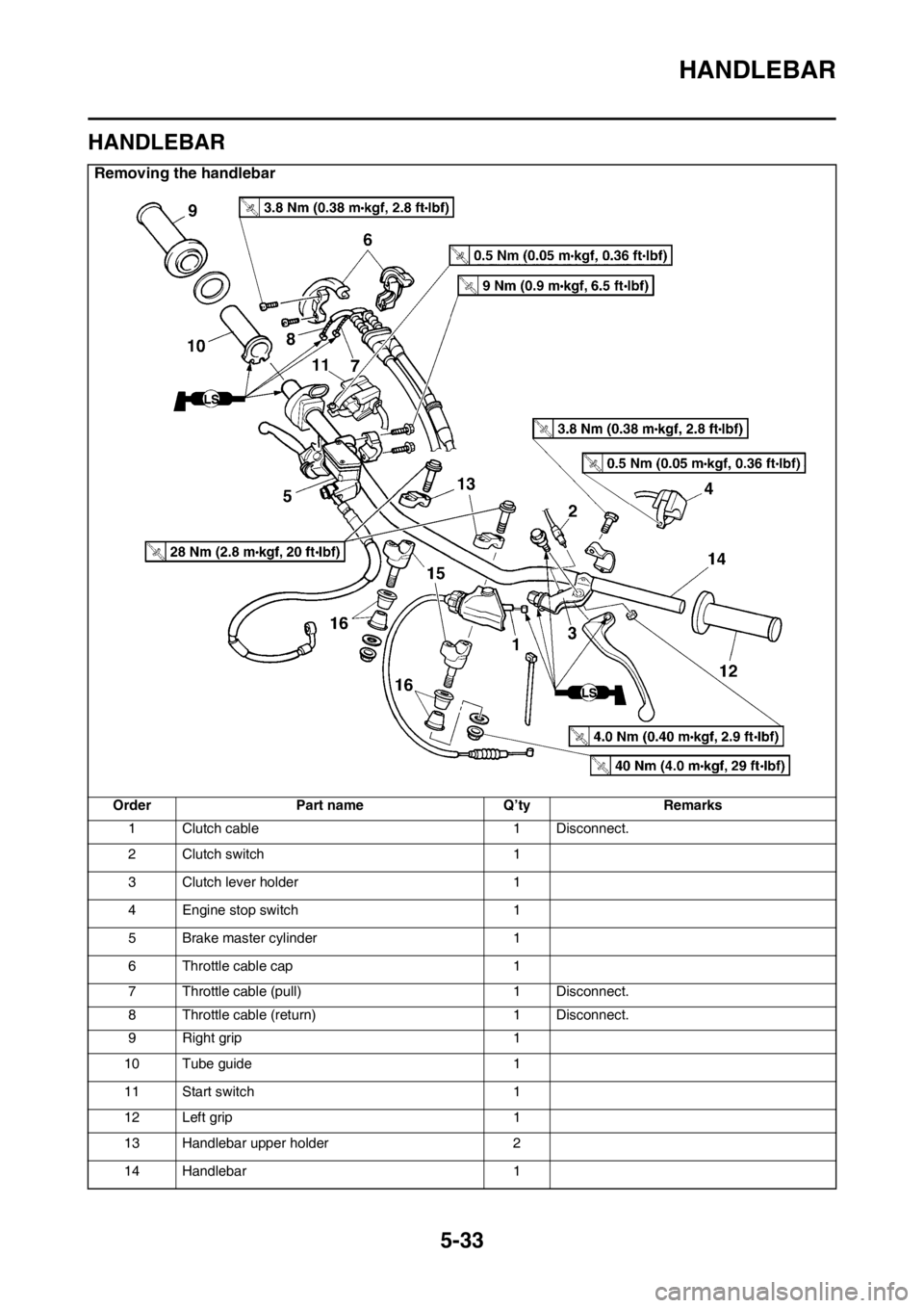
EAS2GC1193
HANDLEBAR
Removing the handlebar
OrderPart name Q’tyRemarks
1 Clutch cable 1 Disconnect.
2 Clutch switch 1
3 Clutch lever holder 1
4 Engine stop switch 1
5 Brake master cylinder 1
6 Throttle cable cap 1
7 Throttle cable (pull) 1 Disconnect.
8 Throttle cable (return) 1 Disconnect.
9 Right grip 1
10 Tube guide 1
11 Start switch 1
12 Left grip 1
13 Handlebar upper holder 2
14 Handlebar 1
Page 189 of 426
HANDLEBAR
5-37
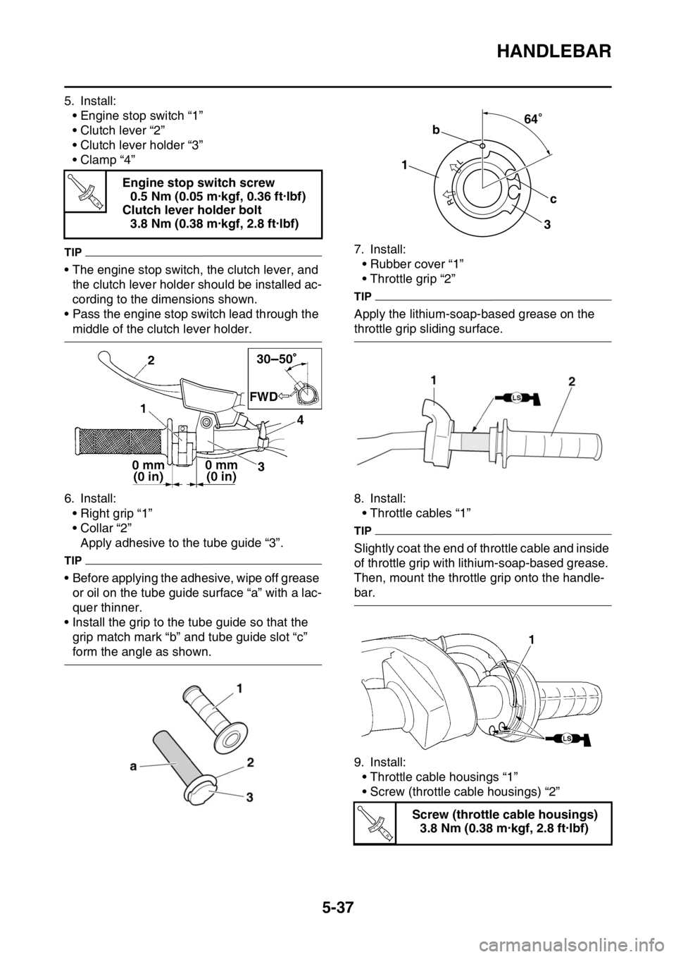
5. Install:• Engine stop switch “1”
• Clutch lever “2”
• Clutch lever holder “3”
•Clamp “4”
TIP
• The engine stop switch, the clutch lever, and the clutch lever holder should be installed ac-
cording to the dimensions shown.
• Pass the engine stop switch lead through the
middle of the clutch lever holder.
6. Install: • Right grip “1”
• Collar “2”Apply adhesive to the tube guide “3”.
TIP
• Before applying the adhesive, wipe off grease or oil on the tube guide surface “a” with a lac-
quer thinner.
• Install the grip to the tube guide so that the grip match mark “b” and tube guide slot “c”
form the angle as shown. 7. Install:
• Rubber cover “1”
• Throttle grip “2”
TIP
Apply the lithium-soap-based grease on the
throttle grip sliding surface.
8. Install:• Throttle cables “1”
TIP
Slightly coat the end of throttle cable and inside
of throttle grip with lithium-soap-based grease.
Then, mount the throttle grip onto the handle-
bar.
9. Install:
• Throttle cable housings “1”
• Screw (throttle cable housings) “2”
EWA
Engine stop switch screw0.5 Nm (0.05 m·kgf, 0.36 ft·lbf)
Clutch lever holder bolt 3.8 Nm (0.38 m·kgf, 2.8 ft·lbf)
T R..
Screw (throttle cable housings)3.8 Nm (0.38 m·kgf, 2.8 ft·lbf)
64
1 b
c
3
64
T R..
Page 220 of 426
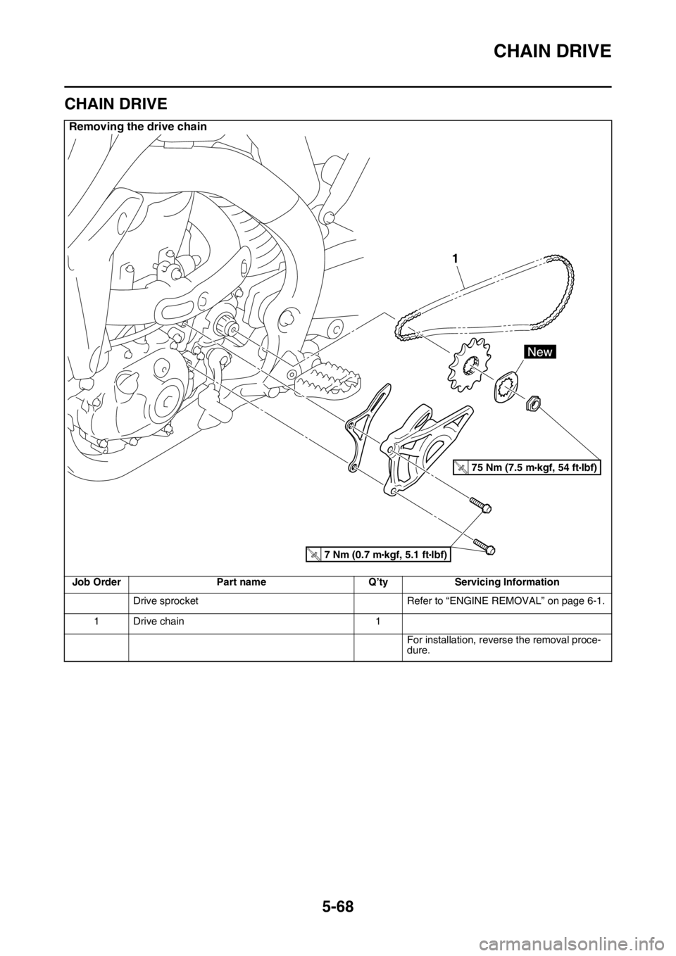
CHAIN DRIVE
5-68
EAS2GC1221
CHAIN DRIVE
Removing the drive chain
Job OrderPart name Q’tyServicing Information
Drive sprocket Refer to “ENGINE REMOVAL” on page 6-1.
1 Drive chain 1
For installation, reverse the removal proce-
dure.
1
T.R.75 Nm (7.5 mlbf)
kgf, 54 ft
T.R.7 Nm (0.7 mlbf)
kgf, 5.1 ft
Page 223 of 426
CHAIN DRIVE
5-71
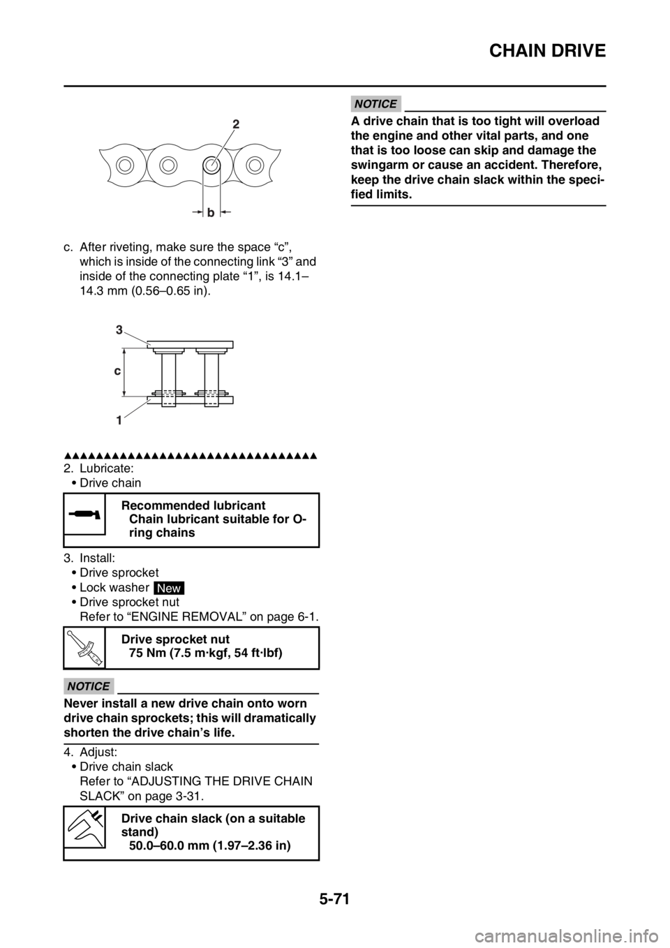
c. After riveting, make sure the space “c”, which is inside of the connecting link “3” and
inside of the connecting plate “1”, is 14.1–
14.3 mm (0.56–0.65 in).
▲▲▲▲▲▲▲▲▲▲▲▲▲▲▲▲▲▲▲▲▲▲▲▲▲▲▲▲▲▲▲▲
2. Lubricate:
•Drive chain
3. Install: • Drive sprocket
• Lock washer
• Drive sprocket nutRefer to “ENGINE REMOVAL” on page 6-1.
ECA
NOTICE
Never install a new drive chain onto worn
drive chain sprockets; this will dramatically
shorten the drive chain’s life.
4. Adjust:• Drive chain slackRefer to “ADJUSTING THE DRIVE CHAIN
SLACK” on page 3-31.
ECA
NOTICE
A drive chain that is too tight will overload
the engine and other vital parts, and one
that is too loose can skip and damage the
swingarm or cause an accident. Therefore,
keep the drive chain slack within the speci-
fied limits.
Recommended lubricant Chain lubricant suitable for O-
ring chains
Drive sprocket nut 75 Nm (7.5 m·kgf, 54 ft·lbf)
Drive chain slack (on a suitable
stand) 50.0–60.0 mm (1.97–2.36 in)
New
T R..
Page 225 of 426

6
ENGINE
ENGINE REMOVAL......................................................................................... 6-1
REMOVING THE SILENCER ..................................................................... 6-6
REMOVING THE EXHAUST PIPE 2.......................................................... 6-6
REMOVING THE DRIVE SPROCKET ....................................................... 6-6
REMOVING THE ENGINE ......................................................................... 6-7
CLEANING THE SPARK ARRESTER ....................................................... 6-7
CHECKING THE SILENCER AND EXHAUST PIPE.................................. 6-8
INSTALLING THE ENGINE........................................................................ 6-8
INSTALLING THE BRAKE PEDAL ............................................................ 6-9
INSTALLING THE DRIVE SPROCKET...................................................... 6-9
INSTALLING THE EXHAUST PIPE AND MUFFLER................................. 6-9
CAMSHAFT .................................................................................................... 6-11
REMOVING THE CAMSHAFT ................................................................. 6-13
CHECKING THE CAMSHAFT.................................................................. 6-14
CHECKING THE TIMING CHAIN AND CAMSHAFT SPROCKET .......... 6-15
CHECKING THE TIMING CHAIN TENSIONERS .................................... 6-15
CHECKING THE DECOMPRESSION SYSTEM.............. ........................ 6-16
INSTALLING THE CAMSHAFTS ............................................................. 6-16
CYLINDER HEAD ........................................................................................... 6-18
REMOVING THE CYLINDER HEAD........................................................ 6-20
CHECKING THE TIMING CHAIN GUIDE (INTAKE SIDE) ...................... 6-20
CHECKING THE CYLINDER HEAD ........................................................ 6-20
INSTALLING THE CYLINDER HEAD ...................................................... 6-21
VALVES AND VALVE SPRINGS ................................................................... 6-23
REMOVING THE VALVES ....................................................................... 6-24
CHECKING THE VALVES AND VALVE GUIDES ................................... 6-25
CHECKING THE VALVE SEATS ............................................................. 6-26
CHECKING THE VALVE SPRINGS......................................................... 6-28
CHECKING THE VALVE LIFTERS .......................................................... 6-29
INSTALLING THE VALVES ..................................................................... 6-29
CYLINDER AND PISTON ............................................................................... 6-31
REMOVING THE PISTON ....................................................................... 6-32
CHECKING THE CYLINDER AND PISTON ............................................ 6-32
CHECKING THE PISTON RINGS............................................................ 6-33
CHECKING THE PISTON PIN ................................................................. 6-34
INSTALLING THE PISTON AND CYLINDER .......................................... 6-34
ELECTRIC STARTER .................................................................................... 6-36
CHECKING THE STARTER MOTOR ...................................................... 6-38
ASSEMBLING THE STARTER MOTOR .................................................. 6-39