YAMAHA WR 450F 2016 User Guide
Manufacturer: YAMAHA, Model Year: 2016, Model line: WR 450F, Model: YAMAHA WR 450F 2016Pages: 426, PDF Size: 10.86 MB
Page 11 of 426

1
2
3
4
5
6
7
8
9
10
TABLE OF CONTENS
GENERAL INFORMATION
SPECIFICATIONS
PERIODIC CHECKS AND
ADJUSTMENTS
TUNING
CHASSIS
ENGINE
COOLING SYSTEM
FUEL SYSTEM
ELECTRICAL SYSTEM
TROUBLESHOOTING
Page 12 of 426

Page 13 of 426

1
GENERAL INFORMATION
LOCATION OF IMPORTANT LABELS............................................................ 1-1
DESCRIPTION .................................................................................................. 1-4
IDENTIFICATION ............................................................................................. 1-5
VEHICLE IDENTIFICATION NUMBER ...................................................... 1-5
ENGINE SERIAL NUMBER ....................................................................... 1-5
VEHICLE EMISSION CONTROL INFORMATION LABEL......................... 1-5
INCLUDED PARTS .......................................................................................... 1-6
SPARK PLUG WRENCH ........................................................................... 1-6
NIPPLE WRENCH...................................................................................... 1-6
HANDLEBAR PROTECTOR .. .................................................................... 1-6
FUEL HOSE JOINT COVER ...................................................................... 1-6
COUPLER FOR CONNECTING OPTIONAL PART................................... 1-6
IMPORTANT INFORMATION .......................................................................... 1-7
PREPARATION FOR REMOVAL A ND DISASSEMBLY............................ 1-7
REPLACEMENT PARTS............................................................................ 1-7
GASKETS, OIL SEALS AND O-RINGS ..................................................... 1-8
LOCK WASHERS/PLATES AND COTTER PINS ...................................... 1-8
BEARINGS AND OIL SEALS ..................................................................... 1-8
CIRCLIPS ................................................................................................... 1-8
BASIC SERVICE INFORMATION .................................................................... 1-9
ELECTRICAL SYSTEM.......... .................................................................... 1-9
SPECIAL TOOLS ........................................................................................... 1-13
CONTROL FUNCTIONS ................................................................................ 1-18
INDICATOR LIGHTS AND WARNING LIGHTS ....................................... 1-18
ENGINE STOP SWITCH .......................................................................... 1-18
START SWITCH....................................................................................... 1-18
CLUTCH LEVER ................................................................................... ... 1-18
SHIFT PEDAL .......................................................................................... 1-19
KICKSTARTER LEVER.......... .................................................................. 1-19
THROTTLE GRIP ..................................................................................... 1-19
FRONT BRAKE LEVER ........................................................................... 1-19
REAR BRAKE PEDAL.............................................................................. 1-19
SIDESTAND ............................................................................................. 1-20
STARTER KNOB/IDLE SCREW .............................................................. 1-20
FUEL TANK CAP ..................................................................................... 1-20
Page 14 of 426

MULTI-FUNCTION DISPLAY......................................................................... 1-21
DESCRIPTION ......................................................................................... 1-21
BASIC MODE ........................................................................................... 1-21
CHANGEOVER TO BASIC MODE /RACE MODE.................................... 1-22
RACE MODE ............................................................................................ 1-23
FUNCTION DIAGRAM ............................................................................. 1-26
STARTING AND BREAK-IN .......................................................................... 1-28
FUEL ........................................................................................................ 1-28
HANDLING NOTE .................................................................................... 1-28
AIR FILTER MAINTENANCE ................................................................... 1-28
STARTING A COLD ENGINE .................................................................. 1-28
STARTING A WARM ENGINE ................................................................. 1-30
BREAK-IN PROCEDURES .... .................................................................. 1-30
MAINTENANCE AFTER BREAK-IN .............................................................. 1-31
MAJOR MAINTENANCE .......................................................................... 1-31
TORQUE-CHECK POINTS ............................................................................ 1-32
MOTORCYCLE CARE AND STORAGE ........................................................ 1-34
CARE........................................................................................................ 1-34
STORAGE ................................................................................................ 1-35
Page 15 of 426
LOCATION OF IMPORTANT LABELS
1-1
EAS2GC1008
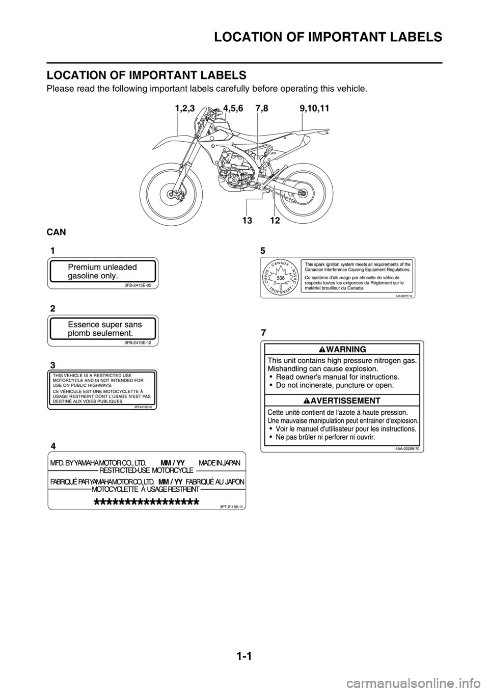
LOCATION OF IMPORTANT LABELS
Please read the following important labels carefully before operating this vehicle.
CAN
9,10,11
7,8
13
12
1,2,3 4,5,6
Page 16 of 426
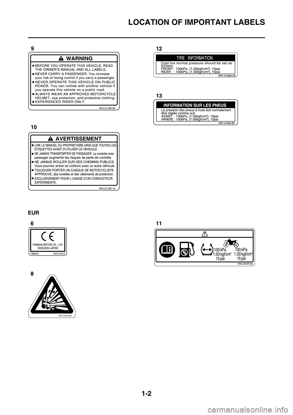
LOCATION OF IMPORTANT LABELS
1-2
EUR
Page 17 of 426
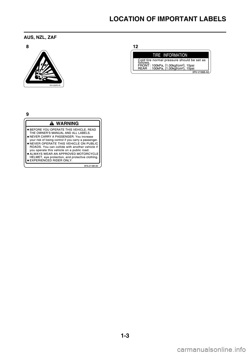
LOCATION OF IMPORTANT LABELS
1-3
AUS, NZL, ZAF
Page 18 of 426
DESCRIPTION
1-4
EAS2GC1009
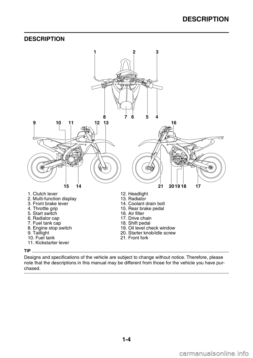
DESCRIPTION
TIP
Designs and specifications of the vehicle are subject to change without notice. Therefore, please
note that the descriptions in this manual may be different from those for the vehicle you have pur-
chased.1. Clutch lever 12. Headlight
2. Multi-function display 13. Radiator
3. Front brake lever 14. Coolant drain bolt
4. Throttle grip 15. Rear brake pedal
5. Start switch 16. Air filter
6. Radiator cap 17. Drive chain
7. Fuel tank cap 18. Shift pedal
8. Engine stop switch 19. Oil level check window
9. Taillight 20. Starter knob/idle screw
10. Fuel tank 21. Front fork
11. Kickstarter lever
32
1
8
10
91 112 1376
54
15 14 21 20 19 18 17 16
Page 19 of 426
IDENTIFICATION
1-5
EAS2GC1010
IDENTIFICATION
There are two significant reasons for knowing
the serial number of your vehicle:
1. When ordering parts, you can give the num-ber to your Yamaha dealer for positive iden-
tification of the model you own.
2. If your vehicle is stolen, the authorities will need the number to search for and identify
your vehicle.
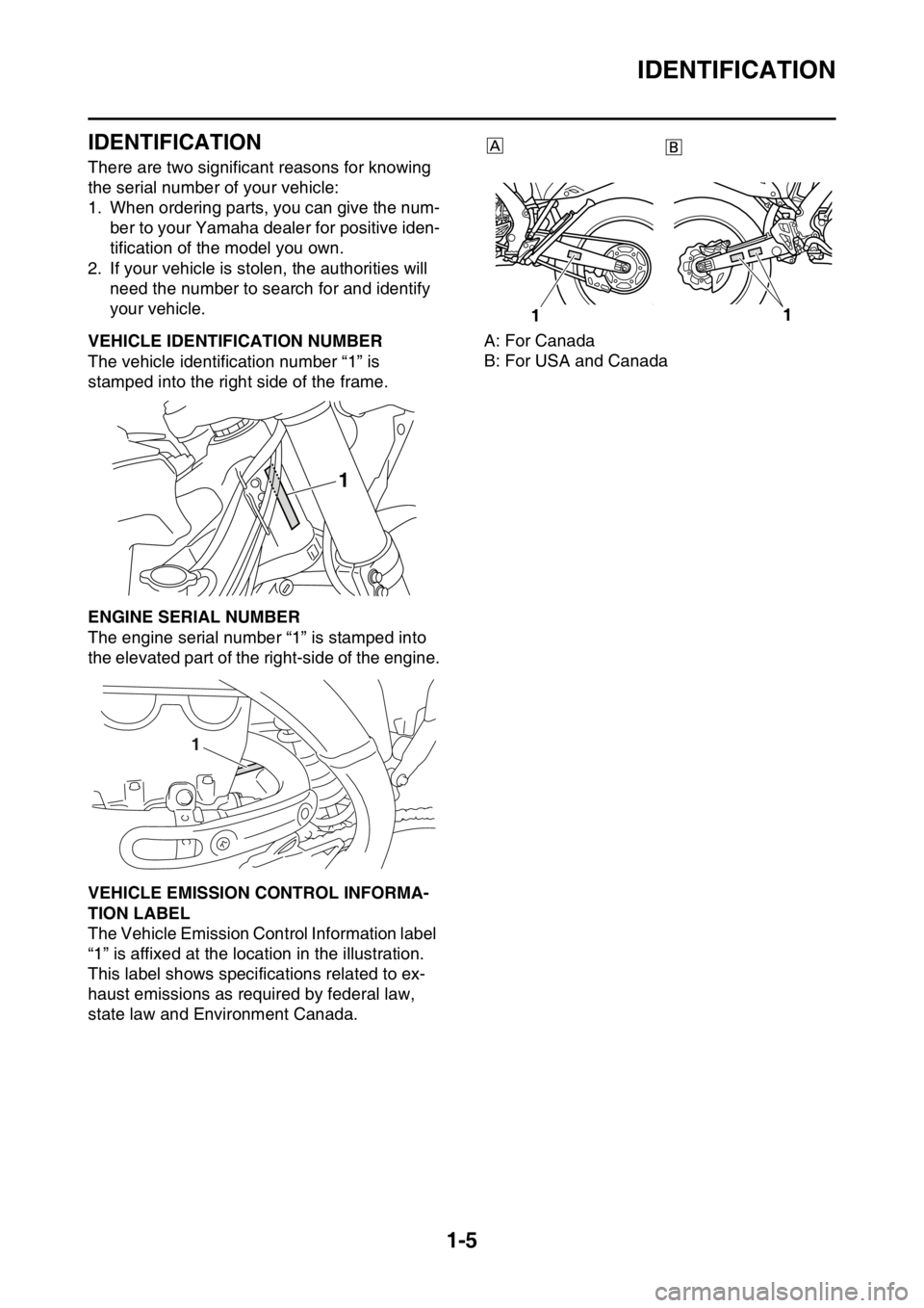
EAS2GC1011VEHICLE IDENTIFICATION NUMBER
The vehicle identification number “1” is
stamped into the right side of the frame.
EAS2GC1012ENGINE SERIAL NUMBER
The engine serial number “1” is stamped into
the elevated part of the right-side of the engine.
EAS2GC1013VEHICLE EMISSION CONTROL INFORMA-
TION LABEL
The Vehicle Emission Control Information label
“1” is affixed at the location in the illustration.
This label shows specifications related to ex-
haust emissions as required by federal law,
state law and Environment Canada. A: For Canada
B: For USA and Canada
1
1
1
1
Page 20 of 426
INCLUDED PARTS
1-6
EAS2GC1014
INCLUDED PARTS
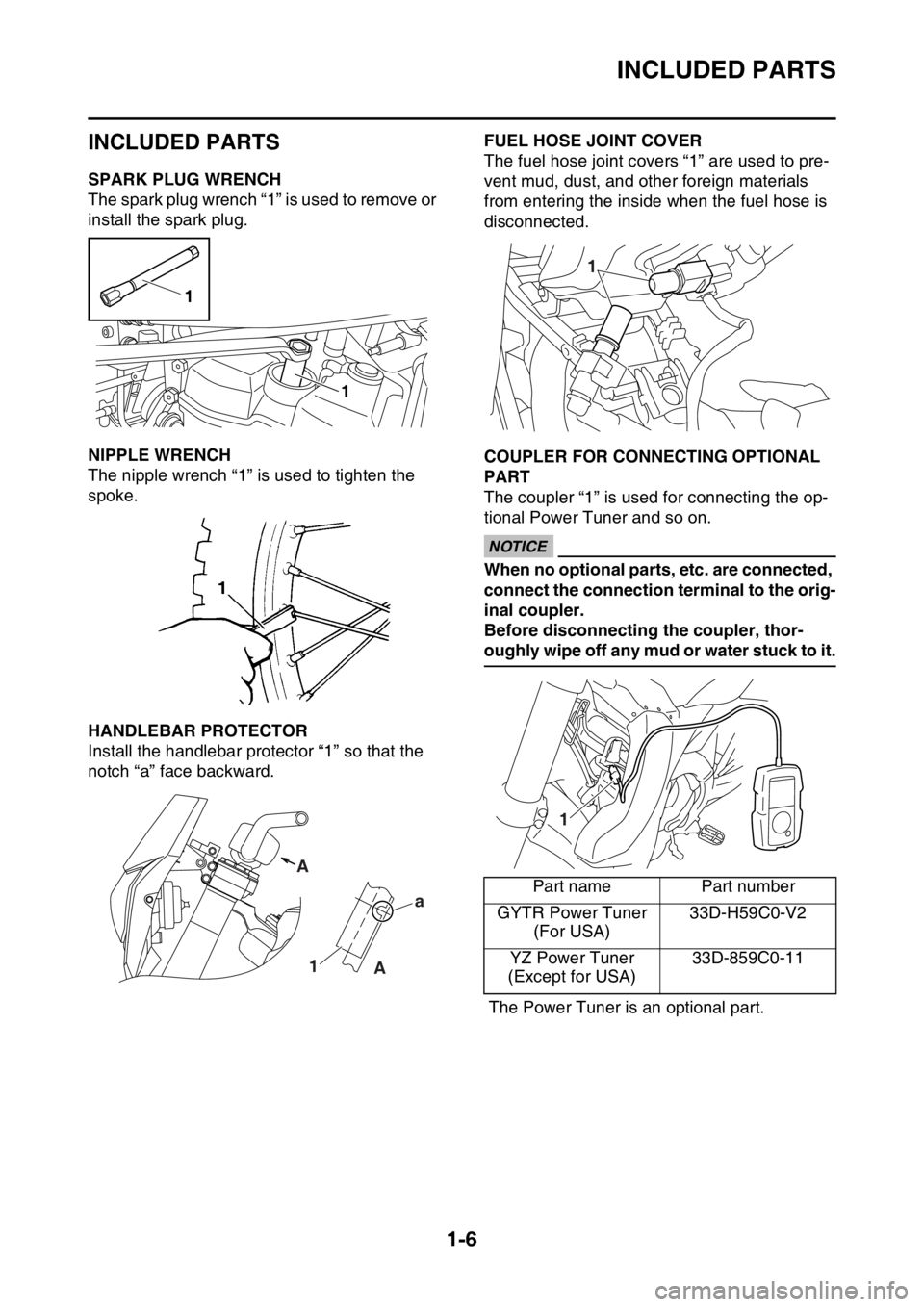
EAS2GC1015SPARK PLUG WRENCH
The spark plug wrench “1” is used to remove or
install the spark plug.
EAS2GC1016NIPPLE WRENCH
The nipple wrench “1” is used to tighten the
spoke.
EAS2GC1017HANDLEBAR PROTECTOR
Install the handlebar protector “1” so that the
notch “a” face backward.
EAS2GC1018FUEL HOSE JOINT COVER
The fuel hose joint covers “1” are used to pre-
vent mud, dust, and other foreign materials
from entering the inside when the fuel hose is
disconnected.
EAS2GC1019COUPLER FOR CONNECTING OPTIONAL
PART
The coupler “1” is used for connecting the op-
tional Power Tuner and so on.
ECA
NOTICE
When no optional parts, etc. are connected,
connect the connection terminal to the orig-
inal coupler.
Before disconnecting the coupler, thor-
oughly wipe off any mud or water stuck to it.
The Power Tuner is an optional part.
1
1
Aa
1 A
Part name Part number
GYTR Power Tuner (For USA) 33D-H59C0-V2
YZ Power Tuner
(Except for USA) 33D-859C0-11
1
1