check engine YAMAHA WR 450F 2016 User Guide
[x] Cancel search | Manufacturer: YAMAHA, Model Year: 2016, Model line: WR 450F, Model: YAMAHA WR 450F 2016Pages: 426, PDF Size: 10.86 MB
Page 45 of 426

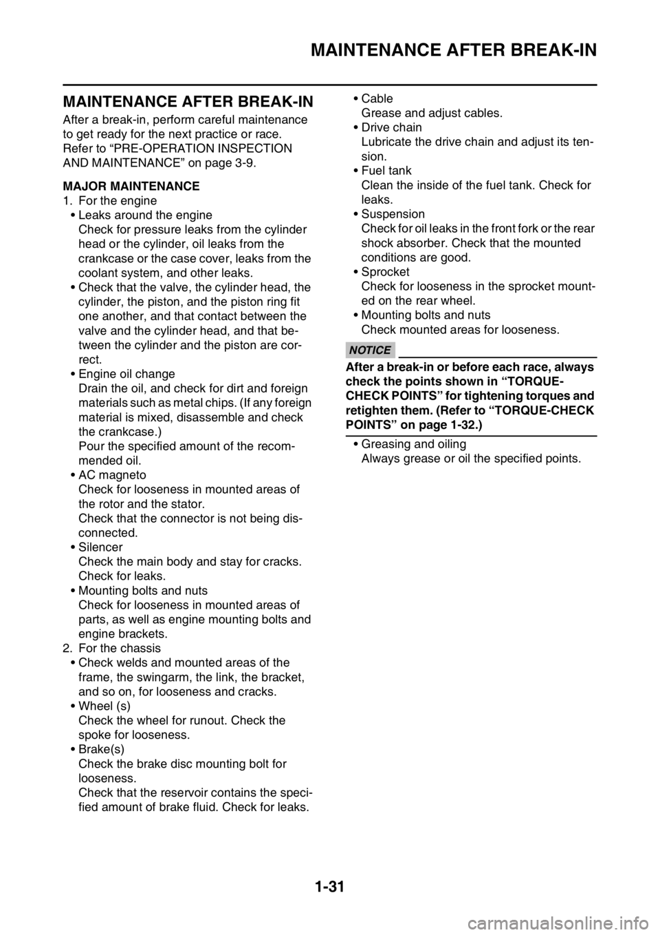
MAINTENANCE AFTER BREAK-IN
1-31
EAS2GC1055
MAINTENANCE AFTER BREAK-IN
After a break-in, perform careful maintenance
to get ready for the next practice or race.
Refer to “PRE-OPERATION INSPECTION
AND MAINTENANCE” on page 3-9.
EAS2GC1056MAJOR MAINTENANCE
1. For the engine• Leaks around the engineCheck for pressure l eaks from the cylinder
head or the cylinder, oil leaks from the
crankcase or the case cover, leaks from the
coolant system, and other leaks.
• Check that the valve, the cylinder head, the cylinder, the piston, and the piston ring fit
one another, and that contact between the
valve and the cylinder head, and that be-
tween the cylinder and the piston are cor-
rect.
• Engine oil change Drain the oil, and check for dirt and foreign
materials such as metal chips. (If any foreign
material is mixed, disassemble and check
the crankcase.)
Pour the specified amount of the recom-
mended oil.
• AC magneto
Check for looseness in mounted areas of
the rotor and the stator.
Check that the connector is not being dis-
connected.
• Silencer Check the main body and stay for cracks.
Check for leaks.
• Mounting bolts and nuts Check for looseness in mounted areas of
parts, as well as engine mounting bolts and
engine brackets.
2. For the chassis
• Check welds and mounted areas of the frame, the swingarm, the link, the bracket,
and so on, for looseness and cracks.
• Wheel (s) Check the wheel for runout. Check the
spoke for looseness.
• Brake(s) Check the brake disc mounting bolt for
looseness.
Check that the reservoir contains the speci-
fied amount of brake fluid. Check for leaks. • Cable
Grease and adjust cables.
•Drive chain
Lubricate the drive chain and adjust its ten-
sion.
• Fuel tank
Clean the inside of the fuel tank. Check for
leaks.
• Suspension
Check for oil leaks in the front fork or the rear
shock absorber. Check that the mounted
conditions are good.
• Sprocket Check for looseness in the sprocket mount-
ed on the rear wheel.
• Mounting bolts and nuts
Check mounted areas for looseness.
ECA
NOTICE
After a break-in or before each race, always
check the points shown in “TORQUE-
CHECK POINTS” for tightening torques and
retighten them. (Refer to “TORQUE-CHECK
POINTS” on page 1-32.)
• Greasing and oilingAlways grease or oil the specified points.
Page 46 of 426

TORQUE-CHECK POINTS
1-32
EAS2GC1057
TORQUE-CHECK POINTS
Frame constructionFrame to rear frame
Frame to engine protector
Combined seat and fuel tank Fuel tank to frame
Engine mounting Frame to engine
Engine bracket to engine
Engine bracket to frame
Seat Seat to frame
Steering Steering stem to handlebar Steering stem to frame
Steering stem to upper bracket
Upper bracket to handlebar
Suspension Front Steering stem to front fork Front fork to upper bracket
Front fork to lower bracket
Rear Link Assembly of links
Link to frame
Link to rear shock absorber
Link to swingarm
Mounting of rear shock absorber Rear shock absorber and frame
Mounting of swingarm Tightening of pivot shaft
Wheel (s) Mounting of wheel Front Tightening of wheel axle
Tightening of axle holder
Tightening of spoke nipple
Rear Tightening of wheel axle Wheel to rear wheel sprocket
Tightening of spoke nipple
Brake(s) Front Brake caliper to front fork
Brake disc to wheel
Tightening of union bolt
Brake master cylinder to handle-
bar
Tightening of bleed screw
Tightening of brake hose holder
Rear Brake pedal to frame Brake disc to wheel
Tightening of union bolt
Brake master cylinder to frame
Tightening of bleed screw
Tightening of brake hose holder
Shift pedal Shift pedal to shift shaft
Page 50 of 426

MOTORCYCLE CARE AND STORAGE
1-36
e. Remove the spark plug cap from the spark plug, and then install the spark plug and the
spark plug cap. WARNING! To prevent
damage or injury from sparking, make
sure to ground the spark plug electrodes
while turning the engine over.
▲▲▲▲▲▲▲▲▲▲▲▲▲▲▲▲▲▲▲▲▲▲▲▲▲▲▲▲▲▲▲▲
4. Lubricate all control cables and the pivoting points of all levers and pedals as well as of
the sidestand/ centerstand.
5. Check and, if necessary, correct the tire air
pressure, and then lift the motorcycle so that
both of its wheels are off the ground. Alter-
natively, turn the wheels a little every month
in order to prevent the tires from becoming
degraded in one spot.
6. Cover the muffler outlet with a plastic bag to
prevent moisture from entering it.
7. Remove the battery and fully charge it. Store it in a cool, dry place and charge it once a
month. Do not store the battery in an exces-
sively cold or warm place [less than 0 °C (30
°F) or more than 30 °C (90 °F)]. For more in-
formation on storing the battery, See page
9-69.
TIP
Make any necessary repairs before storing the
motorcycle.
Page 64 of 426

TIGHTENING TORQUES
2-13
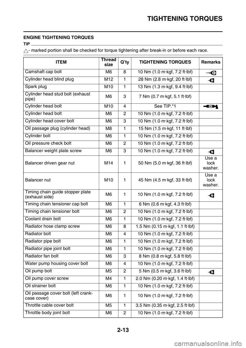
EAS2GC1066ENGINE TIGHTENING TORQUES
TIP
- marked portion shall be checked for torque tightening after break-in or before each race.
ITEM Thread
size Q’ty TIGHTENING TORQUES Remarks
Camshaft cap bolt M6 8 10 Nm (1.0 m·kgf, 7.2 ft·lbf)
Cylinder head blind plug M12 1 28 Nm (2.8 m·kgf, 20 ft·lbf)
Spark plug M10 1 13 Nm (1.3 m·kgf, 9.4 ft·lbf)
Cylinder head stud bolt (exhaust
pipe) M6 3 7 Nm (0.7 m·kgf, 5.1 ft·lbf)
Cylinder head bolt M10 4See TIP.*1
Cylinder head bolt M6 2 10 Nm (1.0 m·kgf, 7.2 ft·lbf)
Cylinder head cover bolt M6 3 10 Nm (1.0 m·kgf, 7.2 ft·lbf)
Oil passage plug (cylinder head) M8 1 15 Nm (1.5 m·kgf, 11 ft·lbf)
Cylinder bolt M6 1 10 Nm (1.0 m·kgf, 7.2 ft·lbf)
Oil pressure check bolt M6 2 10 Nm (1.0 m·kgf, 7.2 ft·lbf)
Balancer weight plate screw M6 3 10 Nm (1.0 m·kgf, 7.2 ft·lbf)
Balancer driven gear nut M14 1 50 Nm (5.0 m·kgf, 36 ft·lbf) Use a
lock
washer.
Balancer nut M10 1 45 Nm (4.5 m·kgf, 33 ft·lbf) Use a
lock
washer.
Timing chain guide stopper plate
(exhaust side) M6 1 10 Nm (1.0 m·kgf, 7.2 ft·lbf)
Timing chain tensioner cap bolt M6 1 6 Nm (0.6 m·kgf, 4.3 ft·lbf)
Timing chain tensioner bolt M6 2 10 Nm (1.0 m·kgf, 7.2 ft·lbf)
Coolant drain bolt M6 1 10 Nm (1.0 m·kgf, 7.2 ft·lbf)
Radiator hose clamp screw M6 8 1.5 Nm (0.15 m·kgf, 1.1 ft·lbf)
Radiator bolt M6 4 10 Nm (1.0 m·kgf, 7.2 ft·lbf)
Radiator pipe bolt M6 1 10 Nm (1.0 m·kgf, 7.2 ft·lbf)
Radiator pipe joint bolt M6 1 10 Nm (1.0 m·kgf, 7.2 ft·lbf)
Radiator fan bolt M6 3 8 Nm (0.8 m·kgf, 5.8 ft·lbf)
Water pump housing cover bolt M6 4 10 Nm (1.0 m·kgf, 7.2 ft·lbf)
Oil pump bolt M5 2 5 Nm (0.5 m·kgf, 3.6 ft·lbf)
Oil pump cover screw M4 1 2.0 Nm (0.20 m·kgf, 1.4 ft·lbf)
Oil strainer bolt M6 1 10 Nm (1.0 m·kgf, 7.2 ft·lbf)
Oil passage cover bolt (left crank-
case cover) M6 1 10 Nm (1.0 m·kgf, 7.2 ft·lbf)
Throttle cable cover bolt M5 1 3.5 Nm (0.35 m·kgf, 2.5 ft·lbf)
Throttle body joint bolt M6 2 10 Nm (1.0 m·kgf, 7.2 ft·lbf)
E
LT
M
LT
LT
LT
Page 65 of 426

TIGHTENING TORQUES
2-14
Throttle body joint clamp boltM5 1 3.0 Nm (0.30 m·kgf, 2.2 ft·lbf)
Air filter joint clamp bolt M4 1 3.5 Nm (0.35 m·kgf, 2.5 ft·lbf)
Air filter case bolt M6 3 7 Nm (0.7 m·kgf, 5.1 ft·lbf)
Air filter bolt M6 1 2.0 Nm (0.20 m·kgf, 1.4 ft·lbf)
Air filter guide holder screw M5 8 2.5 Nm (0.25 m·kgf, 1.8 ft·lbf)
Air filter case cap screw M5 1 2.5 Nm (0.25 m·kgf, 1.8 ft·lbf)
Starter knob/Idle screw M12 1 2.1 Nm (0.21 m·kgf, 1.5 ft·lbf)
Throttle cable nut (pull) M10 1 7 Nm (0.7 m·kgf, 5.1 ft·lbf)
Throttle cable nut (return) M10 1 7 Nm (0.7 m·kgf, 5.1 ft·lbf)
Clutch cable adjuster and locknut M6 1 4.0 Nm (0.40 m·kgf, 2.9 ft·lbf)
Clutch cable locknut (engine side) M8 1 7 Nm (0.7 m·kgf, 5.1 ft·lbf)
Exhaust pipe nut M6 3See TIP.*2
Exhaust pipe protector screw M6 4 10 Nm (1.0 m·kgf, 7.2 ft·lbf)
Exhaust pipe bracket bolt M8 1 20 Nm (2.0 m·kgf, 14 ft·lbf)
Frame and silencer bolt (front) M8 1 30 Nm (3.0 m·kgf, 22 ft·lbf)
Frame and silencer bolt (rear) M8 1 30 Nm (3.0 m·kgf, 22 ft·lbf)
Exhaust pipe clamp bolt M8 2 12 Nm (1.2 m·kgf, 8.7 ft·lbf)
Spark arrester bolt M5 4 9 Nm (0.9 m·kgf, 6.5 ft·lbf)
Muffler cap bolt M5 6 5 Nm (0.5 m·kgf, 3.6 ft·lbf)
Oil nozzle bolt M6 1 10 Nm (1.0 m·kgf, 7.2 ft·lbf)
Engine oil drain bolt M10 1 20 Nm (2.0 m·kgf, 14 ft·lbf)
Crankcase bolt M6 12 12 Nm (1.2 m·kgf, 8.7 ft·lbf)
Clutch cable holder bolt M6 2 10 Nm (1.0 m·kgf, 7.2 ft·lbf)
Crankshaft end accessing screw M36 1 10 Nm (1.0 m·kgf, 7.2 ft·lbf)
Timing mark accessing screw M14 1 6 Nm (0.6 m·kgf, 4.3 ft·lbf)
Drive chain sprocket cover bolt M6 2 7 Nm (0.7 m·kgf, 5.1 ft·lbf)
Crankcase bearing cover plate
screw M6 8 10 Nm (1.0 m·kgf, 7.2 ft·lbf)
Crankcase bearing cover plate
screw (crankshaft) M8 4 18 Nm (1.8 m·kgf, 13 ft·lbf) Crimp.
Clutch cover bolt M6 7 10 Nm (1.0 m·kgf, 7.2 ft·lbf)
Left crankcase cover bolt M6 7 10 Nm (1.0 m·kgf, 7.2 ft·lbf)
Right crankcase cover bolt M6 11 10 Nm (1.0 m·kgf, 7.2 ft·lbf)
Oil filter element cover bolt M6 2 10 Nm (1.0 m·kgf, 7.2 ft·lbf)
Oil level check window bolt M6 1 10 Nm (1.0 m·kgf, 7.2 ft·lbf)
Kick shaft ratchet wheel guide bolt M6 2 12 Nm (1.2 m·kgf, 8.7 ft·lbf)
Kickstarter lever bolt M8 1 33 Nm (3.3 m·kgf, 24 ft·lbf)
ITEM
Thread
size Q’ty TIGHTENING TORQUES Remarks
LT
LT
LT
LT
LT
LT
Page 68 of 426

TIGHTENING TORQUES
2-17
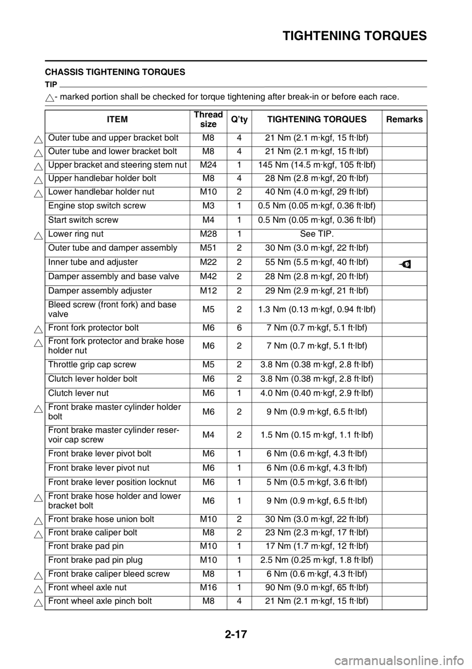
EAS2GC1067CHASSIS TIGHTENING TORQUES
TIP
- marked portion shall be checked for torque tightening after break-in or before each race.
ITEM Thread
size Q’ty TIGHTENING TORQUES Remarks
Outer tube and upper bracket bolt M8 4 21 Nm (2.1 m·kgf, 15 ft·lbf)
Outer tube and lower bracket bolt M8 4 21 Nm (2.1 m·kgf, 15 ft·lbf)
Upper bracket and steering stem nut M24 1 145 Nm (14.5 m·kgf, 105 ft·lbf)
Upper handlebar holder bolt M8 4 28 Nm (2.8 m·kgf, 20 ft·lbf)
Lower handlebar holder nut M10 2 40 Nm (4.0 m·kgf, 29 ft·lbf)
Engine stop switch screw M3 1 0.5 Nm (0.05 m·kgf, 0.36 ft·lbf)
Start switch screw M4 1 0.5 Nm (0.05 m·kgf, 0.36 ft·lbf)
Lower ring nut M28 1See TIP.
Outer tube and damper assembly M51 2 30 Nm (3.0 m·kgf, 22 ft·lbf)
Inner tube and adjuster M22 2 55 Nm (5.5 m·kgf, 40 ft·lbf)
Damper assembly and base valve M42 2 28 Nm (2.8 m·kgf, 20 ft·lbf)
Damper assembly adjuster M12 2 29 Nm (2.9 m·kgf, 21 ft·lbf)
Bleed screw (front fork) and base
valve M5 2 1.3 Nm (0.13 m·kgf, 0.94 ft·lbf)
Front fork protector bolt M6 6 7 Nm (0.7 m·kgf, 5.1 ft·lbf)
Front fork protector and brake hose
holder nut M6 2 7 Nm (0.7 m·kgf, 5.1 ft·lbf)
Throttle grip cap screw M5 2 3.8 Nm (0.38 m·kgf, 2.8 ft·lbf)
Clutch lever holder bolt M6 2 3.8 Nm (0.38 m·kgf, 2.8 ft·lbf)
Clutch lever nut M6 1 4.0 Nm (0.40 m·kgf, 2.9 ft·lbf)
Front brake master cylinder holder
bolt M6 2 9 Nm (0.9 m·kgf, 6.5 ft·lbf)
Front brake master cylinder reser-
voir cap screw M4 2 1.5 Nm (0.15 m·kgf, 1.1 ft·lbf)
Front brake lever pivot bolt M6 1 6 Nm (0.6 m·kgf, 4.3 ft·lbf)
Front brake lever pivot nut M6 1 6 Nm (0.6 m·kgf, 4.3 ft·lbf)
Front brake lever position locknut M6 1 5 Nm (0.5 m·kgf, 3.6 ft·lbf)
Front brake hose holder and lower
bracket bolt M6 1 9 Nm (0.9 m·kgf, 6.5 ft·lbf)
Front brake hose union bolt M10 2 30 Nm (3.0 m·kgf, 22 ft·lbf)
Front brake caliper bolt M8 2 23 Nm (2.3 m·kgf, 17 ft·lbf)
Front brake pad pin M10 1 17 Nm (1.7 m·kgf, 12 ft·lbf)
Front brake pad pin plug M10 1 2.5 Nm (0.25 m·kgf, 1.8 ft·lbf)
Front brake caliper bleed screw M8 1 6 Nm (0.6 m·kgf, 4.3 ft·lbf)
Front wheel axle nut M16 1 90 Nm (9.0 m·kgf, 65 ft·lbf)
Front wheel axle pinch bolt M8 4 21 Nm (2.1 m·kgf, 15 ft·lbf)
LT
Page 97 of 426

3
PERIODIC CHECKS AND ADJUSTMENTS
PERIODIC MAINTENANCE............................................................................. 3-1
INTRODUCTION ........................................................................................ 3-1
PERIODIC MAINTENANCE CHART FOR THE EMISSION
CONTROL SYSTEM ....................... .......................................................... 3-1
GENERAL MAINTENANCE AND LUBRICATION CHART ........................ 3-2
MAINTENANCE INTERVALS FOR COMPETITION USE ......................... 3-4
PRE-OPERATION INSPECTION AND MAINTENANCE ................................. 3-9
GENERAL INSPECTION AND MAINTENANCE........................................ 3-9
ENGINE .......................................................................................................... 3-10
CHECKING THE COOLANT LEVEL ........................................................ 3-10
CHECKING THE COOLING SYSTEM ..................................................... 3-10
CHANGING THE COOLANT.................................................................... 3-10
CHECKING THE RADIATOR CAP .......................................................... 3-11
CHECKING THE RADIATOR CAP VALVE OPENING PRESSURE ....... 3-11
CHECKING THE COOLANT CIRCULATORY SYSTEM FOR LEAKS .... 3-12
ADJUSTING THE CLUTCH LEVER FREE PLAY .................................... 3-12
ADJUSTING THE THROTTLE GRIP FREE PLAY .................................. 3-13
LUBRICATING THE THROTTLE CABLE ................................................ 3-14
CLEANING THE AIR FILTER ELEMENT................................................. 3-14
CHECKING THE THROTTLE BODY JOINT ............................................ 3-15
CHECKING THE BREATHER HOSES .................................................... 3-15
CHECKING THE EXHAUST SYSTEM............................. ........................ 3-15
CHECKING THE FUEL LINE ................................................................... 3-16
CHECKING THE ENGINE OIL LEVEL............................. ........................ 3-16
CHANGING THE ENGINE OIL ................................................................ 3-17
ADJUSTING THE ENGINE IDLING SPEED ......... ................................... 3-19
ADJUSTING THE VALVE CLEARANCE ................................................. 3-20
CLEANING THE SPARK ARRESTER ..................................................... 3-24
CHASSIS ........................................................................................................ 3-25
BLEEDING THE BRAKE SYST EM .......................................................... 3-25
CHECKING THE BRAKE HOSE .............................................................. 3-26
ADJUSTING THE FRONT BRAKE .......................................................... 3-26
ADJUSTING THE REAR BRAKE ............................................................. 3-27
CHECKING THE FRONT BR AKE PADS ................................................. 3-27
CHECKING THE REAR BRAKE PADS ........................... ........................ 3-29
CHECKING THE REAR BRAKE PAD INSULATOR ................................ 3-30
CHECKING THE BRAKE FLUID LEVEL.................................................. 3-30
ADJUSTING THE DRIVE CHAIN SLACK ................................................ 3-31
CHECKING THE FRONT FORK LEGS ................................................... 3-31
CHECKING THE FRONT FORK PROTECTOR GUIDE .......................... 3-32
CLEANING THE FRONT FORK OI L SEAL AND DUST SEAL ................ 3-32
AIR BLEEDING FROM FRONT FORK .................................................... 3-32
ADJUSTING THE FRONT FORK LEGS .................................................. 3-33
CHECKING THE SWINGARM OPERATION ........................................... 3-34
CHECKING THE REAR SUSPENSION ................................................... 3-34
Page 99 of 426

PERIODIC MAINTENANCE
3-1
EAS2GC1074
PERIODIC MAINTENANCE
EAS2GC1075INTRODUCTION
This chapter includes all information necessary to perform recommended checks and adjustments.
If followed, these preventive maintenance procedures will ensure more reliable vehicle operation, a
longer service life and reduce the need for costly ov erhaul work. This information applies to vehicles
already in service as well as to new vehicles that are being prepared for sale. All service technicians
should be familiar with this entire chapter.
EAS2GC1076PERIODIC MAINTENANCE CHART FOR THE EMISSION CONTROL SYSTEM
TIP
• From 4200 mi (7000 km) or 9 months, repeat the maintenance intervals starting from 1800 mi (3000 km) or 3 months.
• Items marked with an asterisk should be performed by a Yamaha dealer as they require special
tools, data and technical skills.
NO. ITEM CHECKS AND MAINTENANCE JOBS INITIAL
ODOMETER READ-
INGS
600 mi (1000
km) or 1 month 1800 mi
(3000
km) or 3 months 3000 mi
(5000
km) or 6 months
1* Fuel line • Check fuel hoses for cracks or dam-
age.
• Replace if necessary.
2Spark plug
• Check condition.
• Adjust gap and clean.
3*Valve clear-
ance • Check and adjust valve clearance
when engine is cold.
4*Air filter ele-
ment • Clean with solvent and apply Yamaha
foam air filter oil or other quality foam
air filter oil.
• Replace if necessary.
5*
Breather
system • Check ventilation hose for cracks or
damage and drain any deposits.
6*Fuel injec-
tion • Adjust engine idling speed.
7Exhaust sys-
tem• Check for leakage.
• Tighten if necessary.
• Replace gasket(s) if necessary.
8Engine oil
• Change (warm engine before drain-
ing).
9Engine oil fil-
ter element•Replace.
10Engine oil
strainer• Clean.
Page 101 of 426

PERIODIC MAINTENANCE
3-3
TIP
• The air filter needs more frequent service if you are riding in unusually wet or dusty areas.
• Hydraulic brake service• After disassembling the brake master cylinders and calipers, always change the fluid. Regularly check the brake fluid levels and f ill the reservoirs as required.
• Every two years replace the internal components of the brake master cylinders and calipers, and
change the brake fluid.
• Replace the brake hoses every four years and if cracked or damaged.
13
Brake and
clutch lever
pivot shafts • Apply lithium-soap-based grease (all-
purpose grease) lightly.
14Brake pedal
pivot shafts• Apply lithium-soap-based grease (all-
purpose grease) lightly.
15Sidestand
pivot• Check operation.
• Apply lithium-soap-based grease (all-
purpose grease) lightly.
16*
Front fork • Check operation and for oil leakage.
• Replace if necessary.
17*Shock ab-
sorber as-
sembly • Check operation and for oil leakage.
• Replace if necessary.
18*Rear sus-
pension link
pivots • Apply molybdenum disulfide grease
lightly.
19*Control ca-
bles • Apply Yamaha chain and cable lube or
engine oil 10W-30 thoroughly.
20*Throttle grip
housing and
cable • Check operation and free play.
• Adjust the throttle cable free play if
necessary.
• Lubricate the throttle grip housing and cable.
21*
Chassis fas-
teners • Check all chassis fitting and fasteners.
• Correct if necessary.
22Battery• Check terminal for looseness and cor-
rosion.
NO. ITEM CHECKS AND MAINTENANCE JOBS
INITIAL
ODOMETER READ-
INGS
600 mi (1000
km) or 1 month 1800 mi
(3000
km) or 3 months 3000 mi
(5000
km) or 6 months
Page 102 of 426

PERIODIC MAINTENANCE
3-4
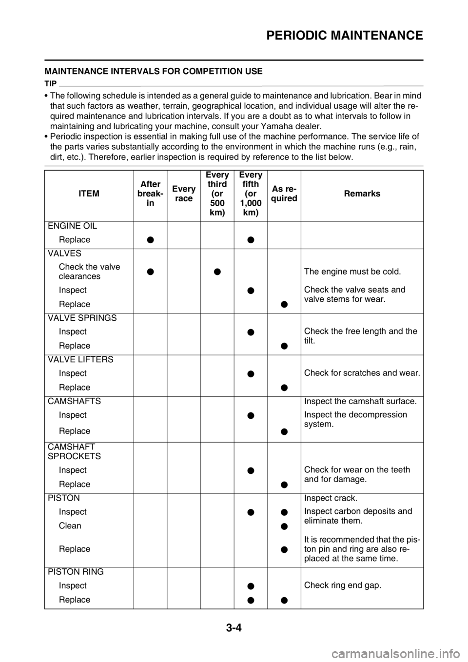
EAS2GC1078MAINTENANCE INTERVALS FOR COMPETITION USE
TIP
• The following schedule is intended as a general guide to maintenance and lubrication. Bear in mind that such factors as weather, terrain, geographical location, and individual usage will alter the re-
quired maintenance and lubrication intervals. If you ar e a doubt as to what intervals to follow in
maintaining and lubricating your ma chine, consult your Yamaha dealer.
• Periodic inspection is essential in making full use of the machine performance. The service life of
the parts varies substantially according to the en vironment in which the machine runs (e.g., rain,
dirt, etc.). Therefore, earlier inspection is required by reference to the list below.
ITEM After
break- in Every
race Every
third (or
500
km) Every
fifth (or
1,000 km) As re-
quired Remarks
ENGINE OIL Replace
VALVES Check the valve
clearances The engine must be cold.
Inspect Check the valve seats and
valve stems for wear.
Replace
VALVE SPRINGS Inspect Check the free length and the
tilt.
Replace
VALVE LIFTERS Inspect Check for scratches and wear.
Replace
CAMSHAFTS Inspect the camshaft surface.
Inspect Inspect the decompression
system.
Replace
CAMSHAFT
SPROCKETS Inspect Check for wear on the teeth
and for damage.
Replace
PISTON Inspect crack.
Inspect Inspect carbon deposits and
eliminate them.
Clean
Replace It is recommended that the pis-
ton pin and ring are also re-
placed at the same time.
PISTON RING
Inspect Check ring end gap.
Replace