YAMAHA WR 450F 2016 Owners Manual
Manufacturer: YAMAHA, Model Year: 2016, Model line: WR 450F, Model: YAMAHA WR 450F 2016Pages: 426, PDF Size: 10.86 MB
Page 251 of 426
VALVES AND VALVE SPRINGS
6-24
EAS2GC1250REMOVING THE VALVES
TIP
Before removing the internal parts of the cylin-
der head (e.g., valves, valve springs, valve
seats), make sure that the valves are properly
sealed.
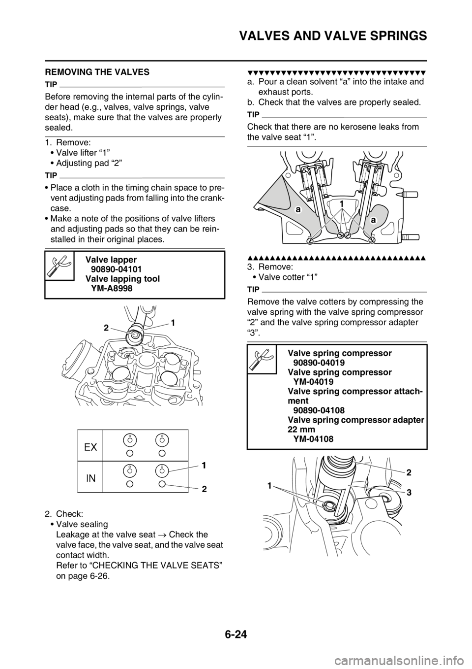
1. Remove:• Valve lifter “1”
• Adjusting pad “2”
TIP
• Place a cloth in the timing chain space to pre-vent adjusting pads from falling into the crank-
case.
• Make a note of the positions of valve lifters and adjusting pads so that they can be rein-
stalled in their original places.
2. Check: • Valve sealingLeakage at the valve seat Check the
valve face, the valve seat, and the valve seat
contact width.
Refer to “CHECKING THE VALVE SEATS”
on page 6-26.
▼▼▼▼▼▼▼▼▼▼▼▼▼▼▼▼▼▼▼▼▼▼▼▼▼▼▼▼▼▼▼▼
a. Pour a clean solvent “a” into the intake and exhaust ports.
b. Check that the valves are properly sealed.
TIP
Check that there are no kerosene leaks from
the valve seat “1”.
▲▲▲▲▲▲▲▲▲▲▲▲▲▲▲▲▲▲▲▲▲▲▲▲▲▲▲▲▲▲▲▲
3. Remove: • Valve cotter “1”
TIP
Remove the valve cotters by compressing the
valve spring with the valve spring compressor
“2” and the valve spring compressor adapter
“3”.
Valve lapper
90890-04101
Valve lapping tool YM-A8998
1
2
Valve spring compressor
90890-04019
Valve spring compressor YM-04019
Valve spring compressor attach-
ment 90890-04108
Valve spring compressor adapter
22 mm YM-04108
a 1
a
Page 252 of 426
VALVES AND VALVE SPRINGS
6-25
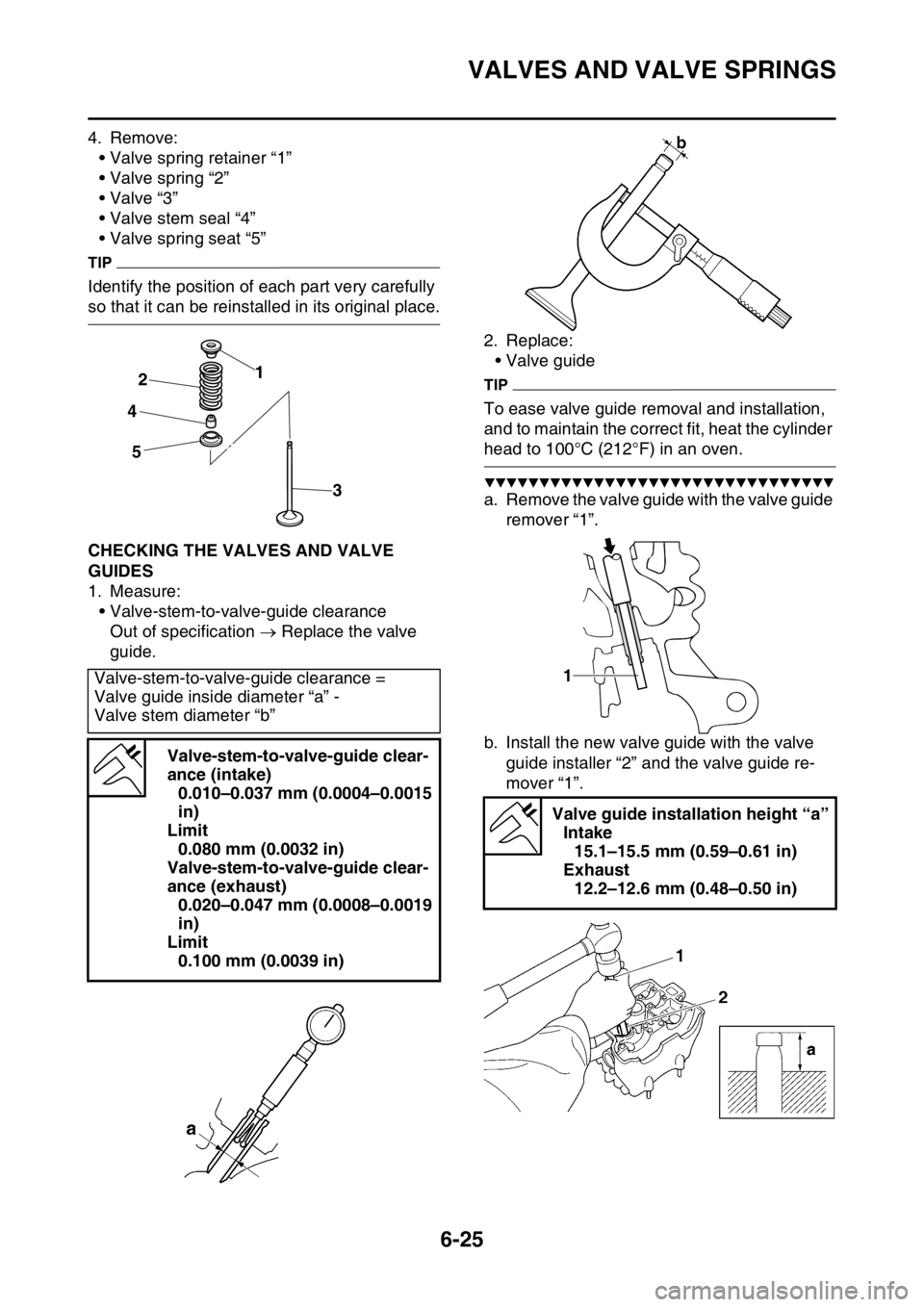
4. Remove:• Valve spring retainer “1”
• Valve spring “2”
•Valve “3”
• Valve stem seal “4”
• Valve spring seat “5”
TIP
Identify the position of each part very carefully
so that it can be reinstalled in its original place.
EAS2GC1251CHECKING THE VALVES AND VALVE
GUIDES
1. Measure:• Valve-stem-to-valve-guide clearance
Out of specification Replace the valve
guide. 2. Replace:
• Valve guide
TIP
To ease valve guide removal and installation,
and to maintain the correct fit, heat the cylinder
head to 100°C (212°F) in an oven.
▼▼▼▼▼▼▼▼▼▼▼▼▼▼▼▼▼▼▼▼▼▼▼▼▼▼▼▼▼▼▼▼
a. Remove the valve guide with the valve guide
remover “1”.
b. Install the new valve guide with the valve guide installer “2” and the valve guide re-
mover “1”.
Valve-stem-to-valve-guide clearance =
Valve guide inside diameter “a” -
Valve stem diameter “b”
Valve-stem-to-valve-guide clear-
ance (intake)0.010–0.037 mm (0.0004–0.0015
in)
Limit 0.080 mm (0.0032 in)
Valve-stem-to-valve-guide clear-
ance (exhaust) 0.020–0.047 mm (0.0008–0.0019
in)
Limit 0.100 mm (0.0039 in)
1
2
4
5
3
Valve guide installation height “a” Intake 15.1–15.5 mm (0.59–0.61 in)
Exhaust 12.2–12.6 mm (0.48–0.50 in)
1
Page 253 of 426
VALVES AND VALVE SPRINGS
6-26
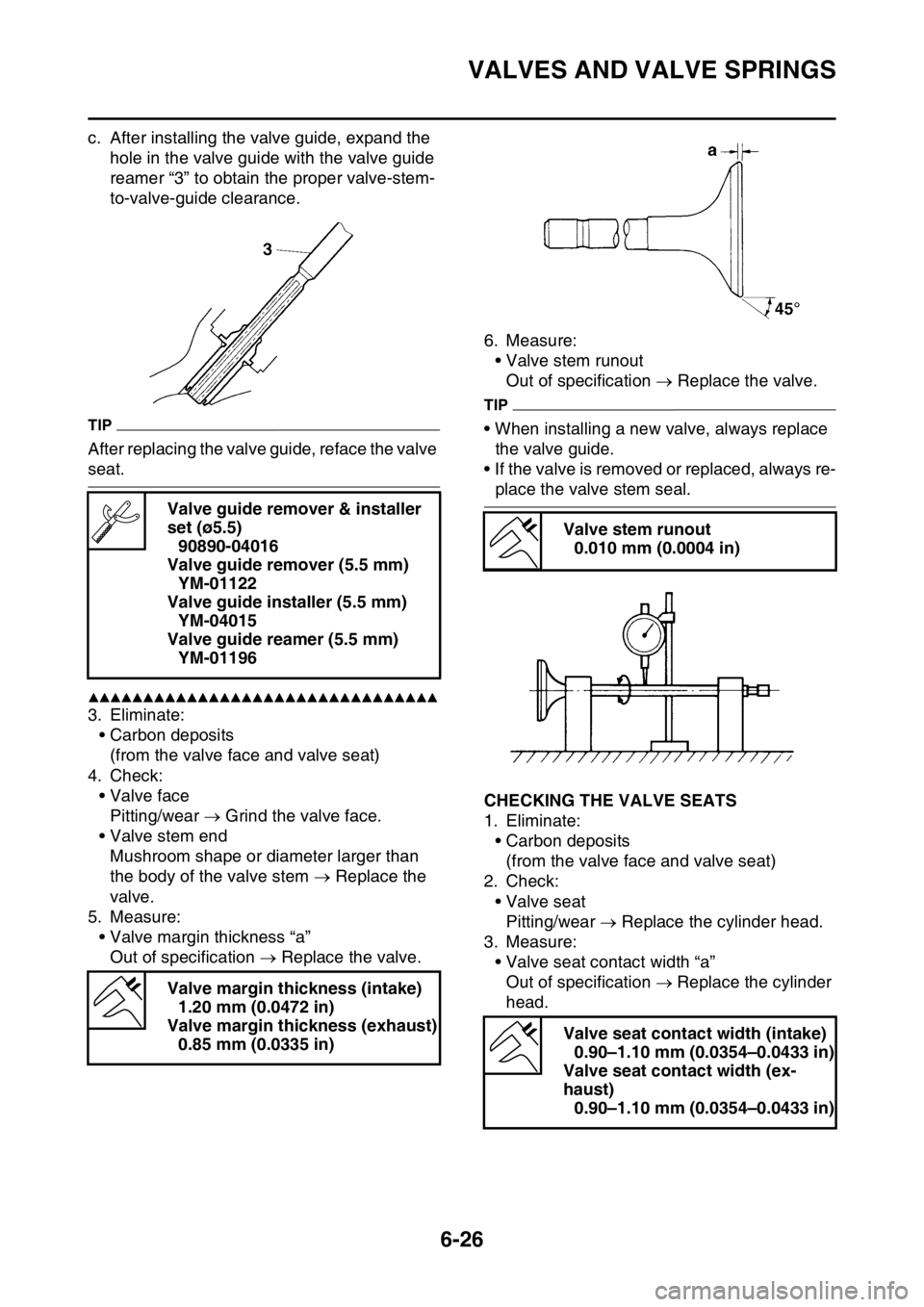
c. After installing the valve guide, expand the hole in the valve guide with the valve guide
reamer “3” to obtain the proper valve-stem-
to-valve-guide clearance.
TIP
After replacing the valve guide, reface the valve
seat.
▲▲▲▲▲▲▲▲▲▲▲▲▲▲▲▲▲▲▲▲▲▲▲▲▲▲▲▲▲▲▲▲
3. Eliminate:• Carbon deposits(from the valve face and valve seat)
4. Check: • Valve facePitting/wear Grind the valve face.
• Valve stem end Mushroom shape or diameter larger than
the body of the valve stem Replace the
valve.
5. Measure: • Valve margin thickness “a”
Out of specification Replace the valve. 6. Measure:
• Valve stem runout
Out of specification Replace the valve.
TIP
• When installing a new valve, always replace
the valve guide.
• If the valve is removed or replaced, always re-
place the valve stem seal.
EAS2GC1252CHECKING THE VALVE SEATS
1. Eliminate: • Carbon deposits(from the valve face and valve seat)
2. Check: • Valve seatPitting/wear Replace the cylinder head.
3. Measure: • Valve seat contact width “a”Out of specification Replace the cylinder
head.
Valve guide remover & installer
set (ø5.5)
90890-04016
Valve guide remover (5.5 mm) YM-01122
Valve guide installer (5.5 mm) YM-04015
Valve guide reamer (5.5 mm) YM-01196
Valve margin thickness (intake) 1.20 mm (0.0472 in)
Valve margin thickness (exhaust) 0.85 mm (0.0335 in)
Valve stem runout 0.010 mm (0.0004 in)
Valve seat contact width (intake) 0.90–1.10 mm (0.0354–0.0433 in)
Valve seat contact width (ex-
haust) 0.90–1.10 mm (0.0354–0.0433 in)
Page 254 of 426
VALVES AND VALVE SPRINGS
6-27
▼▼▼▼▼▼▼▼▼▼▼▼▼▼▼▼▼▼▼▼▼▼▼▼▼▼▼▼▼▼▼▼
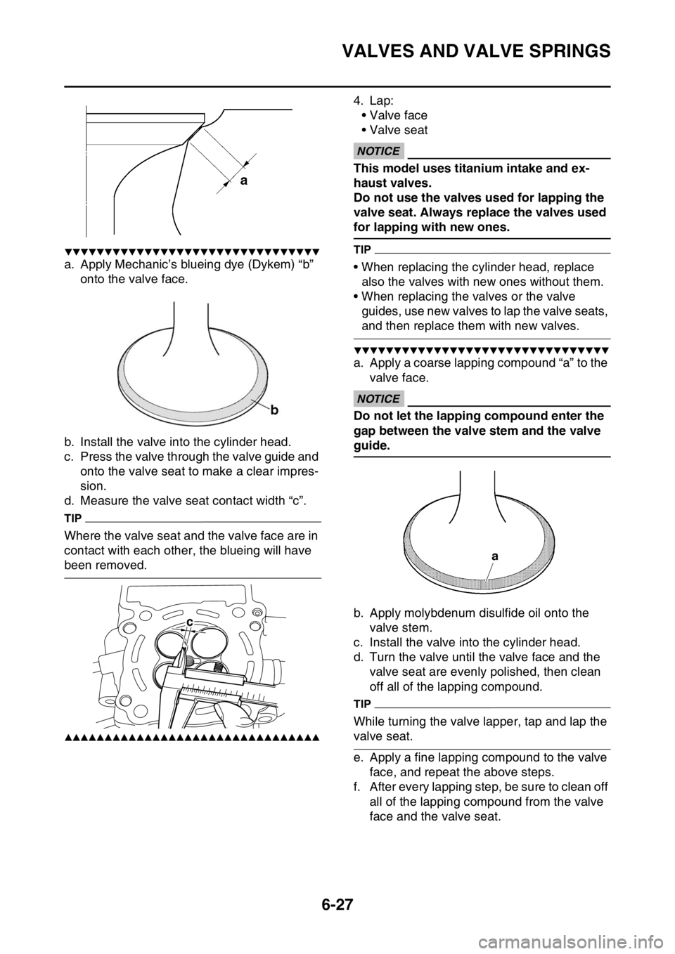
a. Apply Mechanic’s blueing dye (Dykem) “b” onto the valve face.
b. Install the valve into the cylinder head.
c. Press the valve through the valve guide and onto the valve seat to make a clear impres-
sion.
d. Measure the valve seat contact width “c”.
TIP
Where the valve seat and the valve face are in
contact with each other, the blueing will have
been removed.
▲▲▲▲▲▲▲▲▲▲▲▲▲▲▲▲▲▲▲▲▲▲▲▲▲▲▲▲▲▲▲▲
4. Lap:
• Valve face
• Valve seat
ECA
NOTICE
This model uses titanium intake and ex-
haust valves.
Do not use the valves used for lapping the
valve seat. Always replace the valves used
for lapping with new ones.
TIP
• When replacing the cylinder head, replace also the valves with new ones without them.
• When replacing the valves or the valve guides, use new valves to lap the valve seats,
and then replace them with new valves.
▼▼▼▼▼▼▼▼▼▼▼▼▼▼▼▼▼▼▼▼▼▼▼▼▼▼▼▼▼▼▼▼
a. Apply a coarse lapping compound “a” to the
valve face.
ECA
NOTICE
Do not let the lapping compound enter the
gap between the valve stem and the valve
guide.
b. Apply molybdenum disulfide oil onto the valve stem.
c. Install the valve into the cylinder head.
d. Turn the valve until the valve face and the valve seat are evenly polished, then clean
off all of the lapping compound.
TIP
While turning the valve lapper, tap and lap the
valve seat.
e. Apply a fine lapping co mpound to the valve
face, and repeat the above steps.
f. After every lapping step, be sure to clean off all of the lapping compound from the valve
face and the valve seat.
c
Page 255 of 426
VALVES AND VALVE SPRINGS
6-28
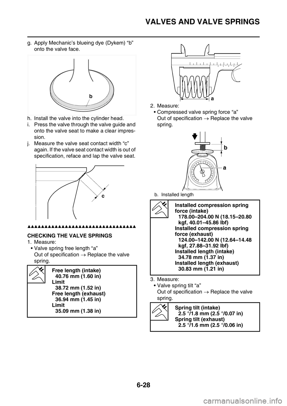
g. Apply Mechanic’s blueing dye (Dykem) “b” onto the valve face.
h. Install the valve into the cylinder head.
i. Press the valve through the valve guide and onto the valve seat to make a clear impres-
sion.
j. Measure the valve seat contact width “c” again. If the valve seat contact width is out of
specification, reface and lap the valve seat.
▲▲▲▲▲▲▲▲▲▲▲▲▲▲▲▲▲▲▲▲▲▲▲▲▲▲▲▲▲▲▲▲
EAS2GC1253CHECKING THE VALVE SPRINGS
1. Measure:
• Valve spring free length “a”Out of specification Replace the valve
spring. 2. Measure:
• Compressed valve spring force “a”
Out of specification Replace the valve
spring.
3. Measure: • Valve spring tilt “a”Out of specification Replace the valve
spring.
Free length (intake)
40.76 mm (1.60 in)
Limit 38.72 mm (1.52 in)
Free length (exhaust) 36.94 mm (1.45 in)
Limit 35.09 mm (1.38 in)
b. Installed length
Installed compression spring
force (intake) 178.00–204.00 N (18.15–20.80
kgf, 40.01–45.86 lbf)
Installed compression spring
force (exhaust) 124.00–142.00 N (12.64–14.48
kgf, 27.88–31.92 lbf)
Installed length (intake) 34.78 mm (1.37 in)
Installed length (exhaust) 30.83 mm (1.21 in)
Spring tilt (intake) 2.5 °/1.8 mm (2.5 °/0.07 in)
Spring tilt (exhaust) 2.5 °/1.6 mm (2.5 °/0.06 in)
Page 256 of 426
VALVES AND VALVE SPRINGS
6-29
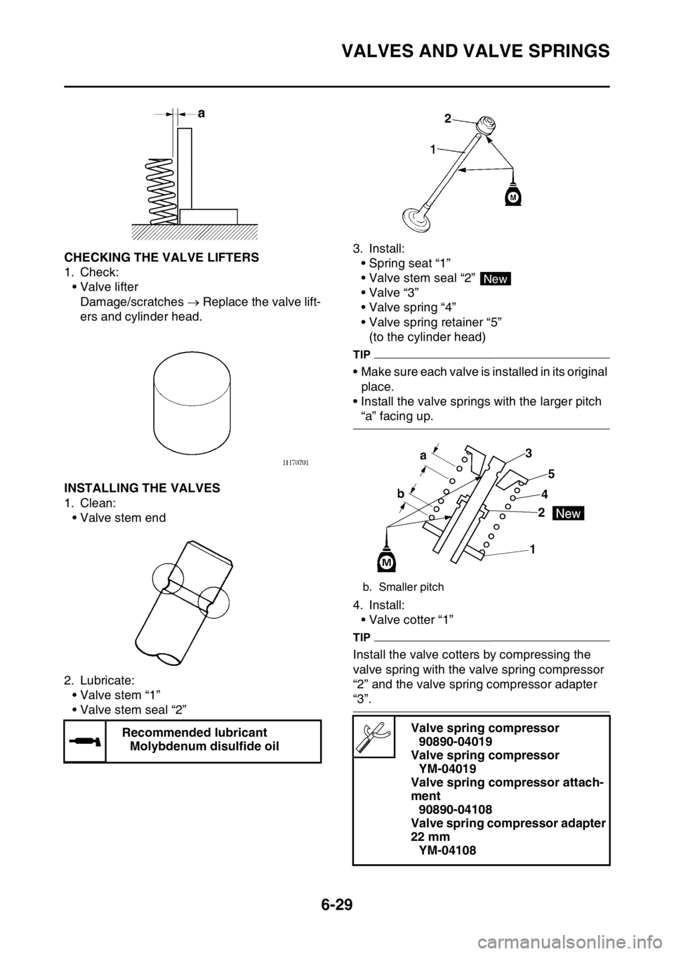
EAS2GC1254CHECKING THE VALVE LIFTERS
1. Check:• Valve lifter
Damage/scratches Replace the valve lift-
ers and cylinder head.
EAS2GC1255INSTALLING THE VALVES
1. Clean: • Valve stem end
2. Lubricate: • Valve stem “1”
• Valve stem seal “2” 3. Install:
• Spring seat “1”
• Valve stem seal “2”
•Valve “3”
• Valve spring “4”
• Valve spring retainer “5”
(to the cylinder head)
TIP
• Make sure each valve is installed in its original place.
• Install the valve springs with the larger pitch
“a” facing up.
4. Install: • Valve cotter “1”
TIP
Install the valve cotters by compressing the
valve spring with the valve spring compressor
“2” and the valve spring compressor adapter
“3”.
Recommended lubricant Molybdenum disulfide oil
b. Smaller pitch
Valve spring compressor90890-04019
Valve spring compressor YM-04019
Valve spring compressor attach-
ment 90890-04108
Valve spring compressor adapter
22 mm YM-04108
New
Page 257 of 426
VALVES AND VALVE SPRINGS
6-30
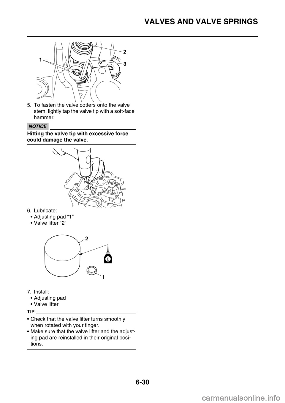
5. To fasten the valve cotters onto the valve stem, lightly tap the valve tip with a soft-face
hammer.
ECA
NOTICE
Hitting the valve tip with excessive force
could damage the valve.
6. Lubricate:
• Adjusting pad “1”
• Valve lifter “2”
7. Install: • Adjusting pad
• Valve lifter
TIP
• Check that the valve lifter turns smoothly when rotated with your finger.
• Make sure that the valve lifter and the adjust- ing pad are reinstalled in their original posi-
tions.
E
1
2
Page 258 of 426
CYLINDER AND PISTON
6-31
EAS2GC1256
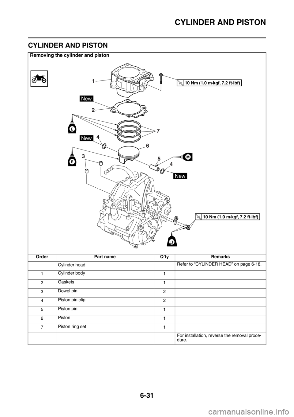
CYLINDER AND PISTON
Removing the cylinder and piston
OrderPart name Q’tyRemarks
Cylinder head Refer to “CYLINDER HEAD” on page 6-18.
1 Cylinder body
1
2 Gaskets
1
3 Dowel pin
2
4 Piston pin clip
2
5 Piston pin
1
6 Piston
1
7 Piston ring set
1
For installation, reverse the removal proce-
dure.
1
2
3
4
4
5
6
7
10 Nm (1.0 m kgf, 7.2 ft Ibf)T.R.
10 Nm (1.0 m kgf, 7.2 ft Ibf)T.R.
E
E
New
New
New
LT
Page 259 of 426
CYLINDER AND PISTON
6-32
EAS2GC1257REMOVING THE PISTON
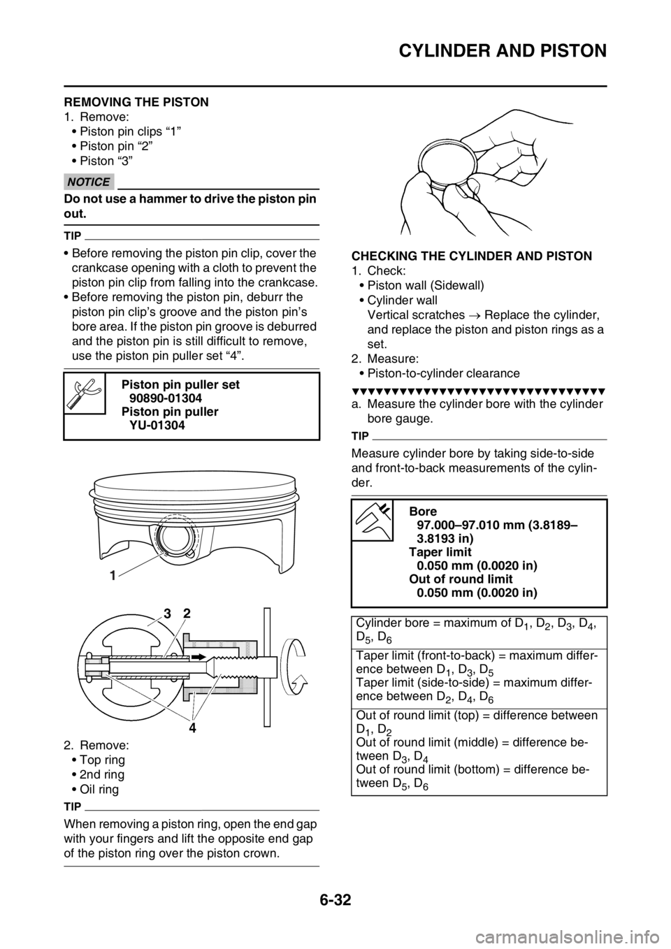
1. Remove:• Piston pin clips “1”
• Piston pin “2”
• Piston “3”
ECA13810
NOTICE
Do not use a hammer to drive the piston pin
out.
TIP
• Before removing the piston pin clip, cover the crankcase opening with a cloth to prevent the
piston pin clip from falling into the crankcase.
• Before removing the piston pin, deburr the piston pin clip’s groove and the piston pin’s
bore area. If the piston pin groove is deburred
and the piston pin is still difficult to remove,
use the piston pin puller set “4”.
2. Remove: • Top ring
• 2nd ring
• Oil ring
TIP
When removing a piston ring, open the end gap
with your fingers and lift the opposite end gap
of the piston ring over the piston crown.
EAS2GC1258CHECKING THE CYLINDER AND PISTON
1. Check:• Piston wall (Sidewall)
• Cylinder wall
Vertical scratches Replace the cylinder,
and replace the piston and piston rings as a
set.
2. Measure: • Piston-to-cylinder clearance
▼▼▼▼▼▼▼▼▼▼▼▼▼▼▼▼▼▼▼▼▼▼▼▼▼▼▼▼▼▼▼▼
a. Measure the cylinder bore with the cylinder
bore gauge.
TIP
Measure cylinder bore by taking side-to-side
and front-to-back measurements of the cylin-
der.
Piston pin puller set
90890-01304
Piston pin puller YU-01304
1
Bore 97.000–97.010 mm (3.8189–
3.8193 in)
Taper limit 0.050 mm (0.0020 in)
Out of round limit 0.050 mm (0.0020 in)
Cylinder bore = maximum of D
1, D2, D3, D4,
D
5, D6
Taper limit (front-to-back) = maximum differ-
ence between D
1, D3, D5Taper limit (side-to-side) = maximum differ-
ence between D
2, D4, D6
Out of round limit (top) = difference between
D
1, D2Out of round limit (middle) = difference be-
tween D
3, D4Out of round limit (bottom) = difference be-
tween D
5, D6
Page 260 of 426
CYLINDER AND PISTON
6-33
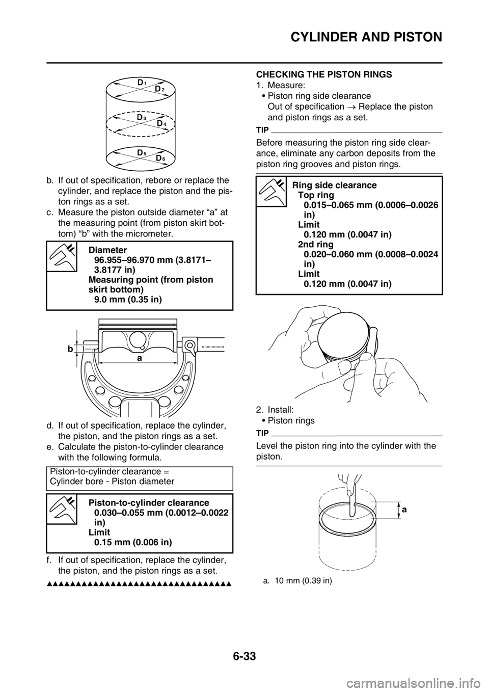
b. If out of specification, rebore or replace the cylinder, and replace the piston and the pis-
ton rings as a set.
c. Measure the piston outside diameter “a” at the measuring point (from piston skirt bot-
tom) “b” with the micrometer.
d. If out of specification, replace the cylinder, the piston, and the piston rings as a set.
e. Calculate the piston-to-cylinder clearance
with the following formula.
f. If out of specification, replace the cylinder, the piston, and the piston rings as a set.
▲▲▲▲▲▲▲▲▲▲▲▲▲▲▲▲▲▲▲▲▲▲▲▲▲▲▲▲▲▲▲▲
EAS2GC1259CHECKING THE PISTON RINGS
1. Measure:• Piston ring side clearanceOut of specification Replace the piston
and piston rings as a set.
TIP
Before measuring the piston ring side clear-
ance, eliminate any carbon deposits from the
piston ring grooves and piston rings.
2. Install: • Piston rings
TIP
Level the piston ring into the cylinder with the
piston.
Diameter
96.955–96.970 mm (3.8171–
3.8177 in)
Measuring point (from piston
skirt bottom) 9.0 mm (0.35 in)
Piston-to-cylinder clearance =
Cylinder bore - Piston diameter Piston-to-cylinder clearance0.030–0.055 mm (0.0012–0.0022
in)
Limit 0.15 mm (0.006 in)
b a
Ring side clearance
Top ring 0.015–0.065 mm (0.0006–0.0026
in)
Limit 0.120 mm (0.0047 in)
2nd ring 0.020–0.060 mm (0.0008–0.0024
in)
Limit 0.120 mm (0.0047 in)
a. 10 mm (0.39 in)