ESP YAMAHA WR 450F 2016 Owners Manual
[x] Cancel search | Manufacturer: YAMAHA, Model Year: 2016, Model line: WR 450F, Model: YAMAHA WR 450F 2016Pages: 426, PDF Size: 10.86 MB
Page 48 of 426
MOTORCYCLE CARE AND STORAGE
1-34
EAS2GC1058
MOTORCYCLE CARE AND STOR-
AGE
EAS2GC1059CARE
While the open design of a motorcycle reveals
the attractiveness of the technology, it also
makes it more vulnerable. Rust and corrosion
can develop even if high-quality components
are used. A rusty exhaust pipe may go unno-
ticed on a car, however, it detracts from the
overall appearance of a motorcycle. Frequent
and proper care does not only comply with the
terms of the warranty, but it will also keep your
motorcycle looking good, extend its life and op-
timize its performance.
Before cleaning
1. Cover the muffler outlet with a plastic bag af-ter the engine has cooled down.
2. Make sure that all caps and covers as well as all electrical coup lers and connectors, in-
cluding the spark plug cap, are tightly in-
stalled.
3. Remove extremely stubborn dirt, like oil
burnt onto the crankcase, with a degreasing
agent and a brush, but never apply such
products onto seals, gaskets, sprockets, the
drive chain and wheel axles. Always rinse
the dirt and degreaser off with water.
Cleaning
ECA
NOTICE
• Avoid using strong acidic wheel cleaners, especially on spoked wheels. If such prod-
ucts are used on hard-to-remove dirt, do
not leave the cleaner on the affected area
any longer than instructed. Also, thor-
oughly rinse the area off with water, imme-
diately dry it, and then apply a corrosion
protection spray.
• Improper cleaning can damage plastic parts (such as cowlings, panels, wind-
shields, headlight lenses, meter lenses,
etc.) and the mufflers. Use only a soft,
clean cloth or sponge with water to clean
plastic. However, if the plastic parts can-
not be thoroughly cleaned with water, di-
luted mild detergent with water may be
used. Be sure to rinse off any detergent
residue using plenty of water, as it is
harmful to plastic parts. • Do not use any harsh chemical products
on plastic parts. Be sure to avoid using
cloths or sponges which have been in con-
tact with strong or abrasive cleaning prod-
ucts, solvent or thinner, fuel (gasoline),
rust removers or inhibitors, brake fluid,
antifreeze or electrolyte.
• Do not use high-pressure washers or steam-jet cleaners since they cause water
seepage and deterioration in the following
areas: seals (of wheel and swingarm bear-
ings, fork and brakes), electric compo-
nents (couplers, connectors, instruments,
switches and lights), breather hoses and
vents.
• For motorcycles equipped with a wind-
shield: Do not use strong cleaners or hard
sponges as they will cause dulling or
scratching. Some cleaning compounds for
plastic may leave scratches on the wind-
shield. Test the product on a small hidden
part of the windshield to make sure that it
does not leave any marks. If the wind-
shield is scratched, use a quality plastic
polishing compound after washing.
After normal use
Remove dirt with warm water, a mild detergent,
and a soft, clean sponge, and then rinse thor-
oughly with clean water. Use a toothbrush or
bottlebrush for hard-to-reach areas. Stubborn
dirt and insects will come off more easily if the
area is covered with a wet cloth for a few min-
utes before cleaning.
After riding in the rain, near the sea or on salt-
sprayed roads
Since sea salt or salt sprayed on roads during
winter are extremely corrosive in combination
with water, carry out the following steps after
each ride in the rain, near the sea or on salt-
sprayed roads.
TIP
Salt sprayed on roads in the winter may remain
well into spring.
1. Clean the motorcycle with cold water and a mild detergent, after the engine has cooled
down.
NOTICE: Do not use warm water since it
increases the corrosive action of the salt.
Page 137 of 426
CHASSIS
3-39
EAS2GC1127LUBRICATING THE DRIVE CHAIN
The drive chain consists of many interacting
parts. If the drive chain is not maintained prop-
erly, it will wear out quickly. Therefore, the drive
chain should be serviced, especially when the
vehicle is used in dusty areas.
This vehicle has a drive chain with small rubber
O-rings between each side plate. Steam clean-
ing, high-pressure washing, certain solvents,
and the use of a coarse brush can damage
these O-rings. Therefore, use only kerosene to
clean the drive chain. Wipe the drive chain dry
and thoroughly lubricate it with engine oil or
chain lubricant that is suitable for O-ring chains.
Do not use any other lubricants on the drive
chain since they may contain solvents that
could damage the O-rings.
EAS2GC1128LUBRICATING THE SIDESTAND
Lubricate the pivoting point and metal-to-metal
moving parts of the sidestand.
EAS2GC1129CHECKING THE CHASSIS FASTENERS
Make sure that all nuts, bolts, and screws are
properly tightened.
Refer to “CHASSIS TIGHTENING TORQUES”
on page 2-17.Recommended lubricant
Chain lubricant suitable for O-
ring chains
Recommended lubricant Lithium-soap-based grease
Page 162 of 426
REAR WHEEL
5-10
EAS2GC1161REMOVING THE REAR WHEEL
1. Use a suitable stand to raise the rear wheel off the ground.
EWA
WARNING
Securely support the vehicle so that there is
no danger of it falling over.
2. Remove:• Rear wheel axle nut “1”
3. Loosen:
• Locknut “2”
4. Tighten: • Adjusting bolt “3”
5. Remove: • Rear wheel axle
• Rear wheel
TIP
• Push the rear wheel forward and remove the drive chain from the rear wheel sprocket.
• Do not depress the brake pedal with the rear
wheel removed.
EAS2GC1162CHECKING THE REAR WHEEL
1. Check:
• Rear wheel axle
• Rear wheel
• Bearing
• Oil sealsRefer to “CHECKING THE FRONT WHEEL”
on page 5-5.
2. Check: •Tire(s)
• Rear wheelDamage/wear Replace.
Refer to “CHECKING THE TIRES” on page
3-36 and “CHECKING THE WHEELS” on
page 3-37.
3. Check: • Spokes
Refer to “CHECKING THE FRONT WHEEL”
on page 5-5. 4. Measure:
• Radial wheel runout
• Lateral wheel runoutRefer to “CHECKING THE FRONT WHEEL”
on page 5-5.
EAS2GC1163DISASSEMBLING THE REAR WHEEL
1. Remove:• Oil seals
• Bearing
Refer to “DISASSEMBLING THE FRONT
WHEEL” on page 5-6.
EAS2GC1164CHECKING AND REPLACING THE REAR
WHEEL SPROCKET
1. Check:• Rear wheel sprocketMore than 1/4 tooth wear “a” Replace the
rear wheel sprocket and the drive sprocket
as a set.
Bent tooth Replace the rear wheel
sprocket and the drive sprocket as a set.
2. Replace: • Rear wheel sprocket
▼▼▼▼▼▼▼▼▼▼▼▼▼▼▼▼▼▼▼▼▼▼▼▼▼▼▼▼▼▼▼▼
a. Remove the self-locking nuts and the rear wheel sprocket.
b. Clean the rear wheel drive hub with a clean
cloth, especially the surfaces that contact
the sprocket.
c. Install the new rear wheel sprocket.
3
1 2
Radial wheel runout limit
2.0 mm (0.08 in)
Lateral wheel runout limit 2.0 mm (0.08 in)
b. Correct
1. Drive chain roller
2. Rear wheel sprocket
Rear wheel sprocket self-locking
nut50 Nm (5.0 m·kgf, 36 ft·lbf)
T R..
Page 213 of 426
REAR SHOCK ABSORBER ASSEMBLY
5-61
EAS2GC1208HANDLING THE REAR SHOCK ABSORBEREWA
WARNING
This rear shock absorber contains highly
compressed nitrogen gas. Before handling
the rear shock absorber, read and make
sure that you understand the following in-
formation. The manufacturer cannot be held
responsible for property damage or person-
al injury that may result from improper han-
dling of the rear shock absorber.
• Do not tamper or attempt to open the rear shock absorber.
• Do not subject the rear shock absorber to an open flame or any other source of high
heat. High heat can cause an explosion
due to excessive gas pressure.
• Do not deform or damage the rear shock absorber in any way. Rear shock absorber
damage will result in poor damping perfor-
mance.
TIP
A break-in is required up to about 50 km of run-
ning.
EAS2GC1209DISPOSING OF A REAR SHOCK ABSORB-
ER
Before disposing the rear shock absorber, be
sure to extract the nitrogen gas from valve “1”.
EWA
WARNING
• Wear protective glasses to prevent your
eyes from damage due to possible gas or
metal chips scattered.
• To dispose of a damaged or a worn-out rear shock absorber, take the unit to your
Yamaha dealer for this disposal proce-
dure.
EAS2GC1210REMOVING THE REAR SHOCK ABSORBER
ASSEMBLY
1. Use a suitable stand to raise the rear wheel off the ground.
EWA
WARNING
Securely support the vehicle so that there is
no danger of it falling over.
2. Remove:• Rear shock absorber assembly lower bolt
“1”
TIP
While removing the rear shock absorber as-
sembly lower bolt, hold the swingarm so that it
does not drop down.
3. Remove:• Rear shock absorber assembly upper bolt
• Rear shock absorber assembly
EAS2GC1211REMOVING THE BEARING
1. Remove:• Stopper ring (upper bearing) “1”
TIP
Press in the bearing while pressing its outer
race and remove the stopper ring.
1
1
Page 237 of 426
ENGINE REMOVAL
6-10
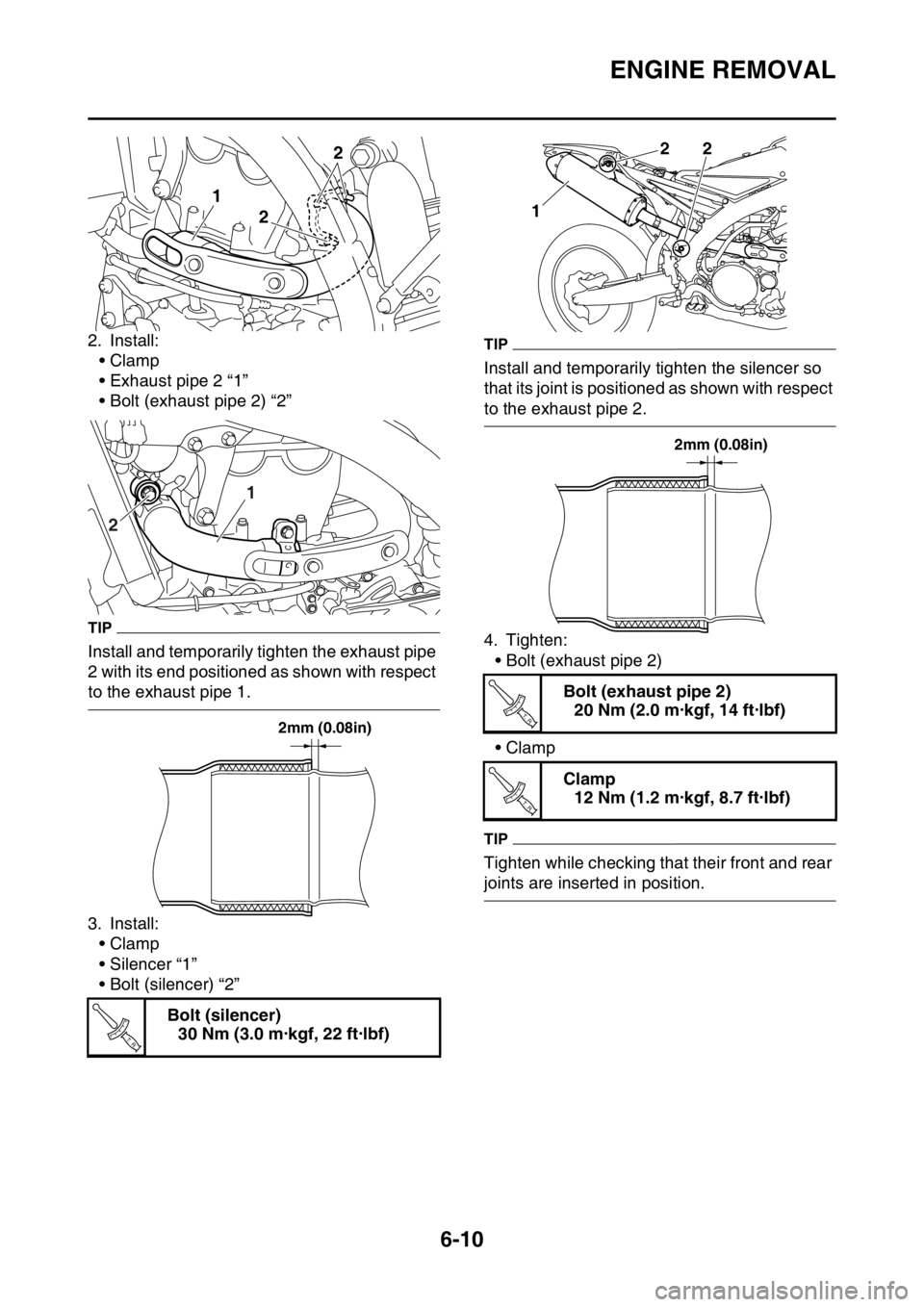
2. Install:•Clamp
• Exhaust pipe 2 “1”
• Bolt (exhaust pipe 2) “2”
TIP
Install and temporarily tighten the exhaust pipe
2 with its end positioned as shown with respect
to the exhaust pipe 1.
3. Install:
•Clamp
• Silencer “1”
• Bolt (silencer) “2”
TIP
Install and temporarily tighten the silencer so
that its joint is positioned as shown with respect
to the exhaust pipe 2.
4. Tighten:• Bolt (exhaust pipe 2)
•Clamp
TIP
Tighten while checking that their front and rear
joints are inserted in position.
Bolt (silencer) 30 Nm (3.0 m·kgf, 22 ft·lbf)
1
2 2
1
2
2mm (0.08in)
T R..
Bolt (exhaust pipe 2) 20 Nm (2.0 m·kgf, 14 ft·lbf)
Clamp 12 Nm (1.2 m·kgf, 8.7 ft·lbf)
1
22
2mm (0.08in)
T R..
T R..
Page 397 of 426
ELECTRICAL COMPONENTS
9-67
EAS27990CHECKING THE BULBS AND BULB SOCK-
ETS
TIP
Do not check any of the lights that use LEDs.
Check each bulb and bulb socket for damage
or wear, proper connections, and also for con-
tinuity between the terminals.
Damage/wear Repair or replace the bulb,
bulb socket or both.
Improperly connected Properly connect.
No continuity Repair or replace the bulb,
bulb socket or both.
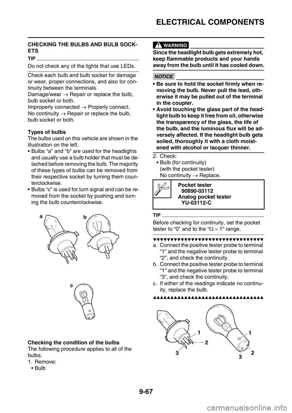
Types of bulbs
The bulbs used on this v ehicle are shown in the
illustration on the left.
• Bulbs “a” and “b” are used for the headlights
and usually use a bulb holder that must be de-
tached before removing the bulb. The majority
of these types of bulbs can be removed from
their respective socket by turning them coun-
terclockwise.
• Bulbs “c” is used for turn signal and can be re- moved from the socket by pushing and turn-
ing the bulb counterclockwise.
Checking the condition of the bulbs
The following procedure applies to all of the
bulbs.
1. Remove: •Bulb
EWA
WARNING
Since the headlight bulb gets extremely hot,
keep flammable products and your hands
away from the bulb until it has cooled down.
ECA
NOTICE
• Be sure to hold the socket firmly when re-moving the bulb. Never pull the lead, oth-
erwise it may be pulled out of the terminal
in the coupler.
• Avoid touching the glass part of the head- light bulb to keep it free from oil, otherwise
the transparency of the glass, the life of
the bulb, and the luminous flux will be ad-
versely affected. If the headlight bulb gets
soiled, thoroughly it with a cloth moist-
ened with alcohol or lacquer thinner.
2. Check: • Bulb (for continuity)(with the pocket tester)
No continuity Replace.
TIP
Before checking for continuity, set the pocket
tester to “0” and to the “ 1” range.
▼▼▼▼▼▼▼▼▼▼▼▼▼▼▼▼▼▼▼▼▼▼▼▼▼▼▼▼▼▼▼▼
a. Connect the positive tester probe to terminal
“1” and the negative tester probe to terminal
“2”, and check the continuity.
b. Connect the positive tester probe to terminal “1” and the negative tester probe to terminal
“3”, and check the continuity.
c. If either of the readings indicate no continu- ity, replace the bulb.
▲▲▲▲▲▲▲▲▲▲▲▲▲▲▲▲▲▲▲▲▲▲▲▲▲▲▲▲▲▲▲▲
Pocket tester90890-03112
Analog pocket tester YU-03112-C