high beam YAMAHA XENTER 125 2012 Owners Manual
[x] Cancel search | Manufacturer: YAMAHA, Model Year: 2012, Model line: XENTER 125, Model: YAMAHA XENTER 125 2012Pages: 84, PDF Size: 1.09 MB
Page 18 of 84

1
2
3
4
5
6
7
8
9
3-2
EAU1044E
INSTRUMENT AND CONTROL FUNCTIONS
EAU49391
Indicator lights and warning
lights
SELECT
RESET
ODOOIL
TRI P 1 BE
L
T TRIP 2
OIL CHANGECLOOK
OUT TEM
P
3
24
1 1
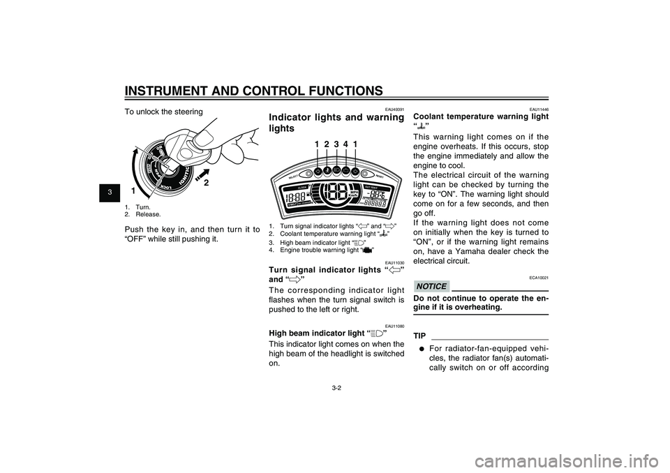
1. Turn signal indicator lights “4” and “6”
2. Coolant temperature warning light “
”
3. High beam indicator light “&”
4. Engine trouble warning light “
”
EAU11030
Turn signal indicator lights “4”
and “6”
The corresponding indicator light
fl ashes when the turn signal switch is
pushed to the left or right.
EAU11080
High beam indicator light “&”
This indicator light comes on when the
high beam of the headlight is switched
on. To unlock the steering
2
1
1. Turn.
2. Release.Push the key in, and then turn it to
“OFF” while still pushing it.
EAU11446
Coolant temperature warning light
“
”
This warning light comes on if the
engine overheats. If this occurs, stop
the engine immediately and allow the
engine to cool.
The electrical circuit of the warning
light can be checked by turning the
key to “ON”. The warning light should
come on for a few seconds, and then
go off.
If the warning light does not come
on initially when the key is turned to
“ON”, or if the warning light remains
on, have a Yamaha dealer check the
electrical circuit.
ECA10021
NOTICEDo not continue to operate the en-
gine if it is overheating.TIP● For radiator-fan-equipped vehi-
cles, the radiator fan(s) automati-
cally switch on or off according
53B-F8199-E0_CS.indd 3-253B-F8199-E0_CS.indd 3-2
2011/11/01 12:32:082011/11/01 12:32:08
Process BlackProcess Black
Page 23 of 84

1
2
3
4
5
6
7
8
9
3-7
EAU1044E
INSTRUMENT AND CONTROL FUNCTIONS
EAU12349
Handlebar switchesLeft
132
1. Dimmer switch “%/&”
2. Turn signal switch “4/6”
3. Horn switch “*”Right
1
1. Start switch “,”
EAU12400
Dimmer switch “&/%”
Set this switch to “&” for the high
beam and to “%” for the low beam.
EAU12460
Turn signal switch “4/6”
To signal a right-hand turn, push this
switch to “6”. To signal a left-hand
turn, push this switch to “4”. When
released, the switch returns to the
center position. To cancel the turn
signal lights, push the switch in after it
has returned to the center position.
EAU12500
Horn switch “*”
Press this switch to sound the horn.
EAUM1132
Start switch “,”
Push this switch while applying the
front or rear brake to crank the en-
gine with the starter. See page 5-1 for
starting instructions prior to starting
the engine.
EAUS2010
Front brake lever
1
1. Front brake leverThe front brake lever is located on
the right handlebar grip. To apply the
front brake, pull this lever toward the
handlebar grip.
This model is equipped with a unifi ed
brake system.
As this system is mechanical, addi-
tional free play can be felt in the front
brake lever when the rear brake lever
is being applied. See “Rear brake
lever” for detailed information on the
unifi ed brake system.
53B-F8199-E0_CS.indd 3-753B-F8199-E0_CS.indd 3-7
2011/11/01 12:32:082011/11/01 12:32:08
Process BlackProcess Black
Page 77 of 84

1
2
3
4
5
6
7
8
9
8-2
SPECIFICATIONS
Caster angle
23.83 degree
Trail
84 mm (3.3 in)Front tireType
Tubeless
Size
100 / 80 - 16M/C 50P
Manufacturer/model
DURO / DM1157FRear tireType
Tubeless
Size
120 / 80 - 16M/C 60P
Manufacturer/model
DURO / DM1157LoadingMaximum load
179 kg (395 lb)Tire air pressure (measured on cold
tires)Loading condition
90 kg (198 lb)
Front
175 kPa (1.75 kgf/cm
2, 25 psi, 1.75 bar)
Rear
200 kPa (2.00 kgf/cm2, 29 psi, 2.00 bar)
Loading condition
90 kg - maximum load
Front
175 kPa (1.75 kgf/cm2, 25 psi, 1.75 bar)Rear
225 kPa (2.25 kgf/cm
2, 33 psi, 2.25 bar)
Front wheelWheel type
Cast wheel
Rim size
J 16M/C � MT2.50Rear wheelWheel type
Cast wheel
Rim size
J 16M/C � MT2.75Front brakeType
Single disc brake
Operation
Right hand operation
Specifi ed brake fl uid
DOT 4Rear brakeType
Drum brake
Operation
Left hand operationFront suspensionType
Telescopic fork
Spring/shock absorber type
Coil spring/oil damper
Wheel travel
100.0 mm (3.94 in)Rear suspensionType
Unit swingSpring/shock absorber type
Coil spring/gas-oil damper
Wheel travel
92.0 mm (3.62 in)
Electrical systemIgnition system
TCI
Charging system
AC magnetoBatteryModel
GT7B-4
Voltage, capacity
12 V, 6.5 AhHeadlightBulb type
Halogen bulbBulb voltage, wattage x quantityHeadlight
12 V, 55 W x 2
Tail/brake light
12V, 0.25 / 1.4W� 1 (LED ASSY)
Front turn signal light
12 V, 10.0 W x 2
Rear turn signal light
12 V, 10.0 W x 2
Auxiliary light
12 V, 5.0 W x 2
License plate light
12 V, 5.0 W x 1
Meter lighting
12V,LED � 6
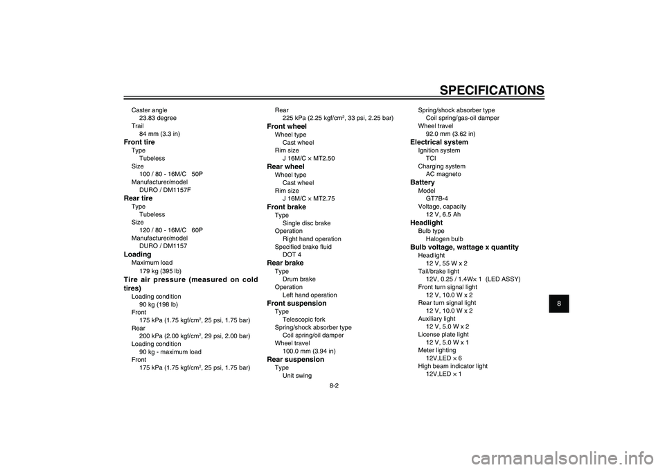
High beam indicator light
12V,LED � 1
53B-F8199-E0_CS.indd 8-253B-F8199-E0_CS.indd 8-2
2011/11/01 12:32:112011/11/01 12:32:11
Process BlackProcess Black
Page 80 of 84

INDEXAAcceleration and deceleration ................... 5-2
Air fi lter and V-belt case air fi lter
elements ............................................... 6-15
Auxiliary light bulb, replacing .................. 6-30BBattery ..................................................... 6-25
Brake fl uid, changing .............................. 6-22
Brake fl uid level, checking ...................... 6-21
Brake lever, front ....................................... 3-7
Brake lever, rear ....................................... 3-8
Brake levers, lubricating .......................... 6-23
Brake pads and shoes, checking ............ 6-20
Braking ...................................................... 5-2CCables, checking and lubricating ............ 6-22
Care .......................................................... 7-1
Carrier ..................................................... 3-14
Catalytic converter .................................. 3-10
Centerstand, checking and lubricating .... 6-23
Coolant .................................................... 6-13
Coolant temperature warning light ............ 3-2
Cowling and panels, removing and
installing .................................................. 6-7DDimmer switch .......................................... 3-7EEngine break-in ......................................... 5-3
Engine idling speed, checking ................ 6-16
Engine oil ................................................ 6-10
Engine trouble warning light ...................... 3-3FFinal transmission oil .............................. 6-12
Front brake lever free play, checking ...... 6-19Front fork, checking ................................ 6-24
Fuel ........................................................... 3-9
Fuel consumption, tips for reducing .......... 5-3
Fuel tank cap ............................................ 3-8
Fuses, replacing ...................................... 6-27
HHandlebar switches ................................... 3-7
Headlight bulb, replacing ........................ 6-28
High beam indicator light .......................... 3-2
Horn switch ............................................... 3-7IIdentifi cation numbers ............................... 9-1
Indicator lights and warning lights ............. 3-2LLicense plate light ................................... 6-31
Luggage holder ....................................... 3-14MMaintenance, emission control system ..... 6-3
Maintenance and lubrication, periodic ...... 6-4
Main switch/steering lock .......................... 3-1
Matte color, caution ................................... 7-1
Model label ................................................ 9-1
Multi-function display ................................ 3-3PParking ...................................................... 5-4
Part locations ............................................ 2-1
Passenger footrest .................................. 3-12RRear brake lever free play, adjusting ...... 6-19SSafe-riding points ...................................... 1-5
Safety information ..................................... 1-1
Seat ......................................................... 3-11
Shock absorber assembly ....................... 3-13Spark plug, checking ................................. 6-9
Specifi cations ............................................ 8-1
Starting off ................................................. 5-2
Starting the engine .................................... 5-1
Start switch ............................................... 3-7
Steering, checking .................................. 6-25
Storage ..................................................... 7-3
Storage compartment (front) ................... 3-12
Storage compartment (rear) .................... 3-13
TTail/brake light ......................................... 6-29
Throttle grip and cable, checking and
lubricating ............................................. 6-23
Throttle grip free play, checking .............. 6-16
Tires ........................................................ 6-17
Tool kit ...................................................... 6-2
Troubleshooting ...................................... 6-32
Troubleshooting charts ........................... 6-33
Turn signal indicator lights ........................ 3-2
Turn signal light bulb (front), replacing .... 6-29
Turn signal light bulb (rear), replacing .... 6-31
Turn signal switch ..................................... 3-7VValve clearance ...................................... 6-17
Vehicle identifi cation number .................... 9-1WWheels .................................................... 6-19
Wheel bearings, checking ....................... 6-25
53B-F8199-E0_CS.indd 9-253B-F8199-E0_CS.indd 9-2
2011/11/01 12:32:112011/11/01 12:32:11
Process BlackProcess Black