key YAMAHA XMAX 125 2008 User Guide
[x] Cancel search | Manufacturer: YAMAHA, Model Year: 2008, Model line: XMAX 125, Model: YAMAHA XMAX 125 2008Pages: 88, PDF Size: 2.61 MB
Page 25 of 88
NOTE:
Even if the key is turned from “ON” to
“OFF” with the hazard lighting on, the
hazard lighting will continue to flash
regardless of the hazard switch posi-
tion. To cancel the hazard lighting, the
key must be turned to “ON” and the
hazard switch must be set to the “h”
position.
The hazard lighting is used in case of
an emergency or to warn other drivers
when your scooter is stopped where
it might be a traffic hazard.
ECA10060
CAUTION:
Do not use the hazard light for an
extended length of time, otherwise
the battery may discharge.
EAU12720
Start switch “g”
With the sidestand up, push this
switch while applying the front or rear
brake to crank the engine with the
starter.
ECA10050
CAUTION:
See page 5-1 for starting instruc-
tions prior to starting the engine.
EAU12900
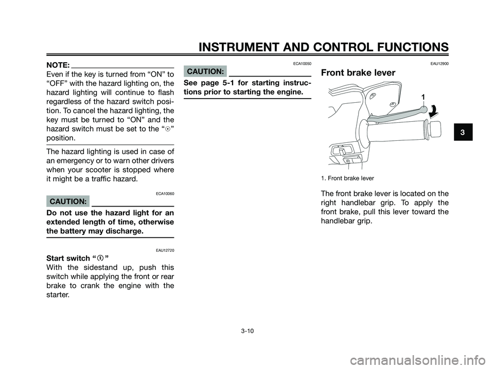
Front brake lever
1. Front brake lever
The front brake lever is located on the
right handlebar grip. To apply the
front brake, pull this lever toward the
handlebar grip.
INSTRUMENT AND CONTROL FUNCTIONS
3-10
3
1B9-F8199-E2.qxd 13/11/07 12:18 Página 25
Page 26 of 88
EAU12950
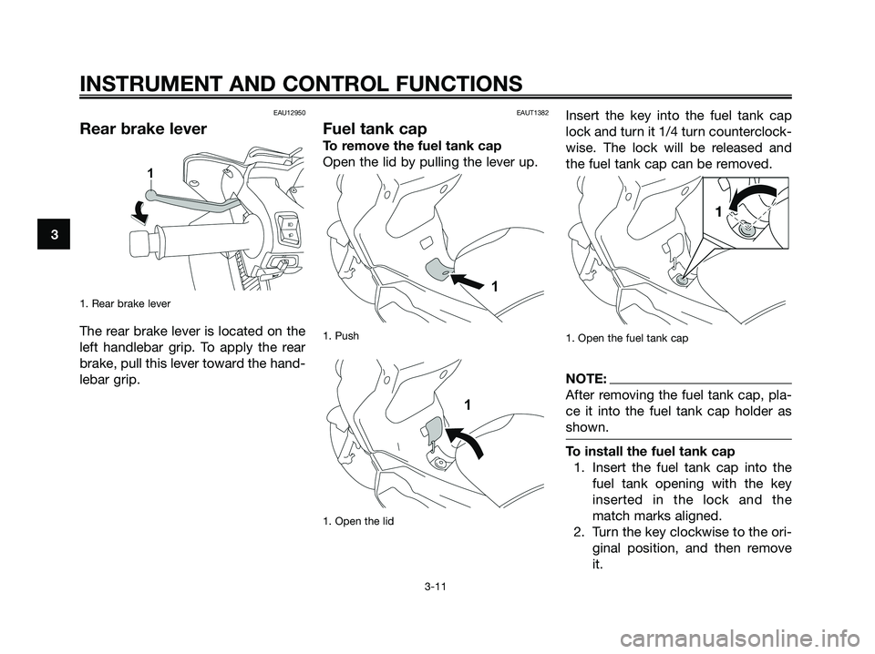
Rear brake lever
1. Rear brake lever
The rear brake lever is located on the
left handlebar grip. To apply the rear
brake, pull this lever toward the hand-
lebar grip.
EAUT1382
Fuel tank cap
To remove the fuel tank cap
Open the lid by pulling the lever up.
1. Push
1. Open the lid
Insert the key into the fuel tank cap
lock and turn it 1/4 turn counterclock-
wise. The lock will be released and
the fuel tank cap can be removed.
1. Open the fuel tank cap
NOTE:
After removing the fuel tank cap, pla-
ce it into the fuel tank cap holder as
shown.
To install the fuel tank cap
1. Insert the fuel tank cap into the
fuel tank opening with the key
inserted in the lock and the
match marks aligned.
2. Turn the key clockwise to the ori-
ginal position, and then remove
it.
INSTRUMENT AND CONTROL FUNCTIONS
3-11
3
1B9-F8199-E2.qxd 13/11/07 12:18 Página 26
Page 27 of 88
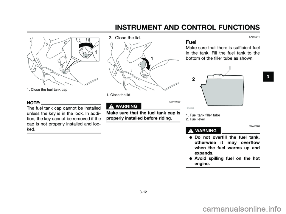
1. Close the fuel tank cap
NOTE:
The fuel tank cap cannot be installed
unless the key is in the lock. In addi-
tion, the key cannot be removed if the
cap is not properly installed and loc-
ked.
3. Close the lid.
1. Close the lid
EWA10130
s s
WARNING
Make sure that the fuel tank cap is
properly installed before riding.
EAU13211
Fuel
Make sure that there is sufficient fuel
in the tank. Fill the fuel tank to the
bottom of the filler tube as shown.
1. Fuel tank filler tube
2. Fuel level
EWA10880
s s
WARNING
●Do not overfill the fuel tank,
otherwise it may overflow
when the fuel warms up and
expands.
●Avoid spilling fuel on the hot
engine.
INSTRUMENT AND CONTROL FUNCTIONS
3-12
3
1B9-F8199-E2.qxd 13/11/07 12:18 Página 27
Page 29 of 88
EAU13932
Seat
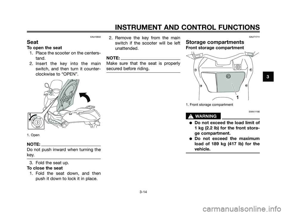
To open the seat
1. Place the scooter on the centers-
tand.
2. Insert the key into the main
switch, and then turn it counter-
clockwise to “OPEN”.
1. Open
NOTE:
Do not push inward when turning the
key.
3. Fold the seat up.
To close the seat
1. Fold the seat down, and then
push it down to lock it in place.2. Remove the key from the main
switch if the scooter will be left
unattended.
NOTE:
Make sure that the seat is properly
secured before riding.
EAUT1711
Storage compartments
Front storage compartment
1. Front storage compartment
EWA11190
s s
WARNING
●Do not exceed the load limit of
1 kg (2.2 lb) for the front stora-
ge compartment.
●Do not exceed the maximum
load of 189 kg (417 lb) for the
vehicle.
INSTRUMENT AND CONTROL FUNCTIONS
3-14
3
1B9-F8199-E2.qxd 13/11/07 12:18 Página 29
Page 30 of 88
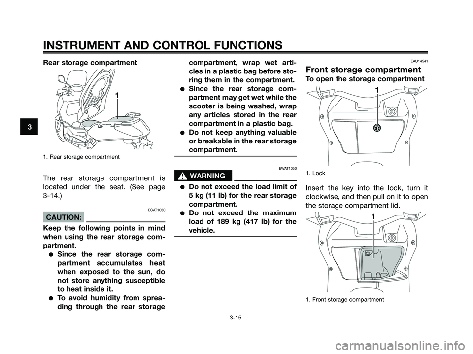
Rear storage compartment
1. Rear storage compartment
The rear storage compartment is
located under the seat. (See page
3-14.)
ECAT1030
CAUTION:
Keep the following points in mind
when using the rear storage com-
partment.
●Since the rear storage com-
partment accumulates heat
when exposed to the sun, do
not store anything susceptible
to heat inside it.
●To avoid humidity from sprea-
ding through the rear storagecompartment, wrap wet arti-
cles in a plastic bag before sto-
ring them in the compartment.
●Since the rear storage com-
partment may get wet while the
scooter is being washed, wrap
any articles stored in the rear
compartment in a plastic bag.
●Do not keep anything valuable
or breakable in the rear storage
compartment.
EWAT1050
s s
WARNING
●Do not exceed the load limit of
5 kg (11 lb) for the rear storage
compartment.
●Do not exceed the maximum
load of 189 kg (417 lb) for the
vehicle.
EAU14541
Front storage compartment
To open the storage compartment
1. Lock
Insert the key into the lock, turn it
clockwise, and then pull on it to open
the storage compartment lid.
1. Front storage compartment
INSTRUMENT AND CONTROL FUNCTIONS
3-15
3
1B9-F8199-E2.qxd 13/11/07 12:18 Página 30
Page 31 of 88
To close the storage compartment
Push the storage compartment lid
into the original position, and then
remove the key.
EWA10961
s s
WARNING
●Do not exceed the load limit of
1 kg (2.2 lb) for the storage
compartment.
●Do not exceed the maximum
load of 189 kg (417 lb) for the
vehicle.
EAUT1060
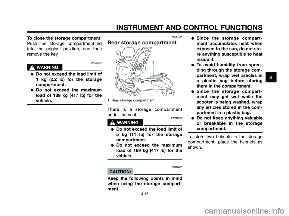
Rear storage compartment
1. Rear storage compartment
There is a storage compartment
under the seat.
EWA10960
s s
WARNING
●Do not exceed the load limit of
5 kg (11 lb) for the storage
compartment.
●Do not exceed the maximum
load of 189 kg (417 lb) for the
vehicle.
ECA10080
CAUTION:
Keep the following points in mind
when using the storage compart-
ment.
●Since the storage compart-
ment accumulates heat when
exposed to the sun, do not sto-
re anything susceptible to heat
inside it.
●To avoid humidity from sprea-
ding through the storage com-
partment, wrap wet articles in
a plastic bag before storing
them in the compartment.
●Since the storage compart-
ment may get wet while the
scooter is being washed, wrap
any articles stored in the com-
partment in a plastic bag.
●Do not keep anything valuable
or breakable in the storage
compartment.
To store two helmets in the storage
compartment, place the helmets as
shown.
INSTRUMENT AND CONTROL FUNCTIONS
3
3-16
1B9-F8199-E2.qxd 13/11/07 12:18 Página 31
Page 34 of 88
INSTRUMENT AND CONTROL FUNCTIONS
3-19
3
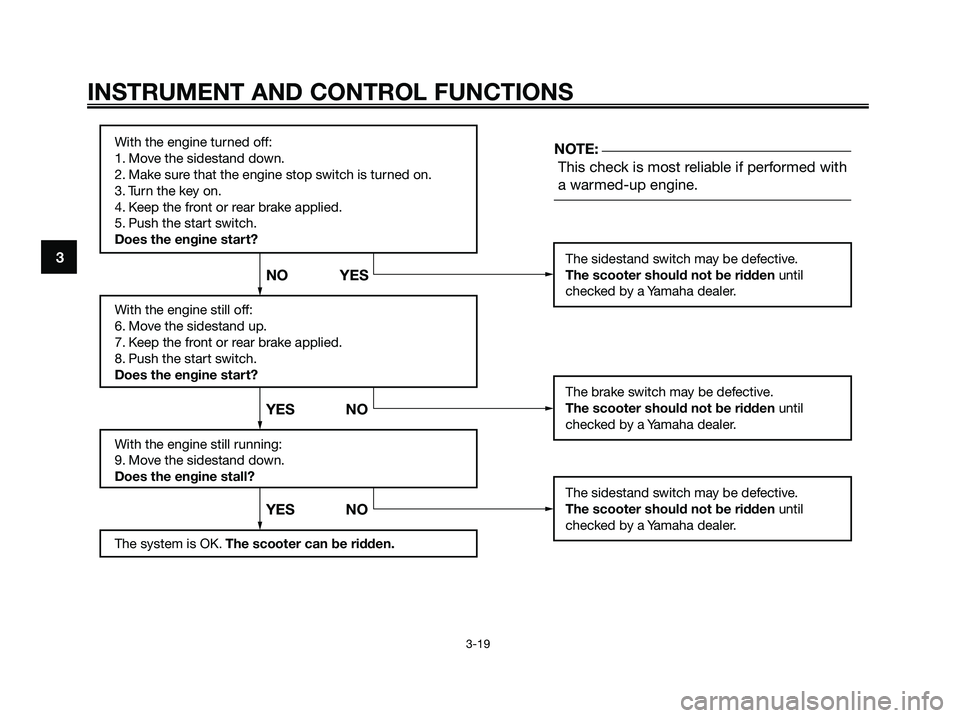
With the engine turned off:
1. Move the sidestand down.
2. Make sure that the engine stop switch is turned on.
3. Turn the key on.
4. Keep the front or rear brake applied.
5. Push the start switch.
Does the engine start?
With the engine still off:
6. Move the sidestand up.
7. Keep the front or rear brake applied.
8. Push the start switch.
Does the engine start?
With the engine still running:
9. Move the sidestand down.
Does the engine stall?
The system is OK. The scooter can be ridden.
This check is most reliable if performed with
a warmed-up engine.
The sidestand switch may be defective.
The scooter should not be ridden until
checked by a Yamaha dealer.
The brake switch may be defective.
The scooter should not be ridden until
checked by a Yamaha dealer.
The sidestand switch may be defective.
The scooter should not be ridden until
checked by a Yamaha dealer.
YES NO YES NO NO YESNOTE:
1B9-F8199-E2.qxd 13/11/07 12:18 Página 34
Page 38 of 88
EAU15980
EWA10870
s s
WARNING
●Become thoroughly familiar
with all operating controls and
their functions before riding.
Consult a Yamaha dealer
regarding any control or func-
tion that you do not thoroughly
understand.
●Never start the engine or ope-
rate it in a closed area for any
length of time. Exhaust fumes
are poisonous, and inhaling
them can cause loss of cons-
ciousness and death within a
short time. Always make sure
that there is adequate ventila-
tion.
●For safety, always start the
engine with the centerstand
down.
EAUM2230
Starting the engineECA10250
CAUTION:
See page 5-4 for engine break-in
instructions prior to operating the
vehicle for the first time.
In order for the ignition circuit cut-off
system to enable starting, the sides-
tand must be up.
EWA10290
s s
WARNING
●Before starting the engine,
check the function of the igni-
tion circuit cut-off system
according to the procedure
described on page 3-18.
●Never ride with the sidestand
down.
1. Turn the key to “ON”.ECAM1080
CAUTION:
The following warning lights and
indicator light should come on for a
few seconds, then go off.
●Fuel level warning light
●Engine trouble warning light
●Immobilizer system indicator
lightIf a warning or indicator light does
not go off, see page 3-3 for the
corresponding warning and indica-
tor light circuit check.
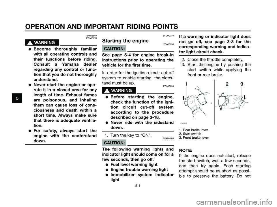
2. Close the throttle completely.
3. Start the engine by pushing the
start switch while applying the
front or rear brake.
1. Rear brake lever
2. Start switch
3. Front brake lever
NOTE:
If the engine does not start, release
the start switch, wait a few seconds,
and then try again. Each starting
attempt should be as short as possi-
ble to preserve the battery. Do not
OPERATION AND IMPORTANT RIDING POINTS
5-1
5
1B9-F8199-E2.qxd 13/11/07 12:18 Página 38
Page 41 of 88
EAU16830
Engine break-in
There is never a more important
period in the life of your engine than
the period between 0 and 1000 km
(600 mi). For this reason, you should
read the following material carefully.
Since the engine is brand new, do not
put an excessive load on it for the first
1000 km (600 mi). The various parts in
the engine wear and polish themsel-
ves to the correct operating clearan-
ces. During this period, prolonged
full-throttle operation or any condition
that might result in engine overhea-
ting must be avoided.
EAUM2280
0 ~ 500 km (0 ~ 300 mi)
Avoid prolonged operation above 1/3
throttle.
500 ~ 1000 km (300 ~ 600 mi)
Avoid prolonged operation above 1/2
throttle.
ECAM1090
CAUTION:
After 1000 km (600 mi) of operation,
the engine oil and final transmis-
sion oil must be changed, and the
engine oil filter element replaced.
1000 km (600 mi) and beyond
The vehicle can now be operated nor-
mally.
ECA10270
CAUTION:
If any engine trouble should occur
during the engine break-in period,
immediately have a Yamaha dealer
check the vehicle.
EAU17212
Parking
When parking, stop the engine, and
then remove the key from the main
switch.
EWA10310
s s
WARNING
●Since the engine and exhaust
system can become very hot,
park in a place where pedes-
trians or children are not likely
to touch them.
●Do not park on a slope or on
soft ground, otherwise the
vehicle may overturn.
ECA10380
CAUTION:
Never park in an area where there
are fire hazards such as grass or
other flammable materials.
OPERATION AND IMPORTANT RIDING POINTS
5-4
5
1B9-F8199-E2.qxd 13/11/07 12:18 Página 41
Page 69 of 88
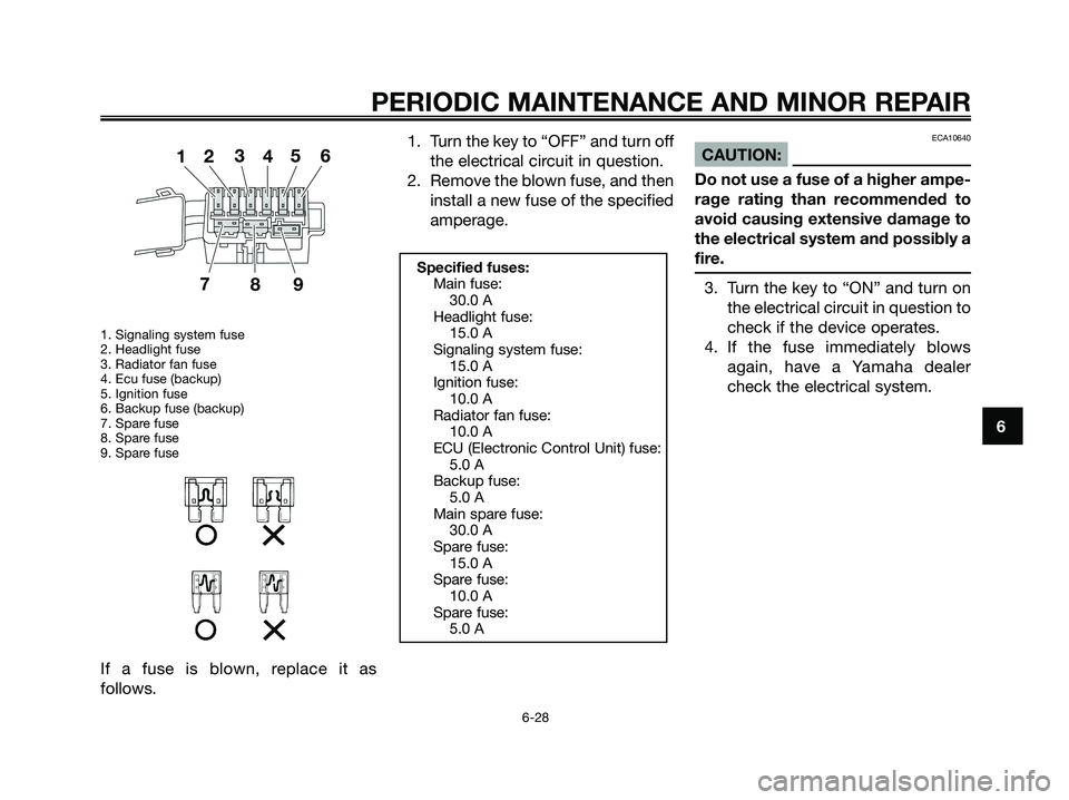
1. Signaling system fuse
2. Headlight fuse
3. Radiator fan fuse
4. Ecu fuse (backup)
5. Ignition fuse
6. Backup fuse (backup)
7. Spare fuse
8. Spare fuse
9. Spare fuse
If a fuse is blown, replace it as
follows.1. Turn the key to “OFF” and turn off
the electrical circuit in question.
2. Remove the blown fuse, and then
install a new fuse of the specified
amperage.
ECA10640
CAUTION:
Do not use a fuse of a higher ampe-
rage rating than recommended to
avoid causing extensive damage to
the electrical system and possibly a
fire.
3. Turn the key to “ON” and turn on
the electrical circuit in question to
check if the device operates.
4. If the fuse immediately blows
again, have a Yamaha dealer
check the electrical system.
Specified fuses:
Main fuse:
30.0 A
Headlight fuse:
15.0 A
Signaling system fuse:
15.0 A
Ignition fuse:
10.0 A
Radiator fan fuse:
10.0 A
ECU (Electronic Control Unit) fuse:
5.0 A
Backup fuse:
5.0 A
Main spare fuse:
30.0 A
Spare fuse:
15.0 A
Spare fuse:
10.0 A
Spare fuse:
5.0 A
PERIODIC MAINTENANCE AND MINOR REPAIR
6-28
6
1B9-F8199-E2.qxd 13/11/07 12:18 Página 69