key battery YAMAHA XMAX 125 2008 Owners Manual
[x] Cancel search | Manufacturer: YAMAHA, Model Year: 2008, Model line: XMAX 125, Model: YAMAHA XMAX 125 2008Pages: 88, PDF Size: 2.61 MB
Page 25 of 88

NOTE:
Even if the key is turned from “ON” to
“OFF” with the hazard lighting on, the
hazard lighting will continue to flash
regardless of the hazard switch posi-
tion. To cancel the hazard lighting, the
key must be turned to “ON” and the
hazard switch must be set to the “h”
position.
The hazard lighting is used in case of
an emergency or to warn other drivers
when your scooter is stopped where
it might be a traffic hazard.
ECA10060
CAUTION:
Do not use the hazard light for an
extended length of time, otherwise
the battery may discharge.
EAU12720
Start switch “g”
With the sidestand up, push this
switch while applying the front or rear
brake to crank the engine with the
starter.
ECA10050
CAUTION:
See page 5-1 for starting instruc-
tions prior to starting the engine.
EAU12900
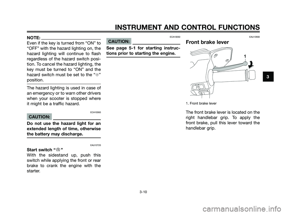
Front brake lever
1. Front brake lever
The front brake lever is located on the
right handlebar grip. To apply the
front brake, pull this lever toward the
handlebar grip.
INSTRUMENT AND CONTROL FUNCTIONS
3-10
3
1B9-F8199-E2.qxd 13/11/07 12:18 Página 25
Page 38 of 88

EAU15980
EWA10870
s s
WARNING
●Become thoroughly familiar
with all operating controls and
their functions before riding.
Consult a Yamaha dealer
regarding any control or func-
tion that you do not thoroughly
understand.
●Never start the engine or ope-
rate it in a closed area for any
length of time. Exhaust fumes
are poisonous, and inhaling
them can cause loss of cons-
ciousness and death within a
short time. Always make sure
that there is adequate ventila-
tion.
●For safety, always start the
engine with the centerstand
down.
EAUM2230
Starting the engineECA10250
CAUTION:
See page 5-4 for engine break-in
instructions prior to operating the
vehicle for the first time.
In order for the ignition circuit cut-off
system to enable starting, the sides-
tand must be up.
EWA10290
s s
WARNING
●Before starting the engine,
check the function of the igni-
tion circuit cut-off system
according to the procedure
described on page 3-18.
●Never ride with the sidestand
down.
1. Turn the key to “ON”.ECAM1080
CAUTION:
The following warning lights and
indicator light should come on for a
few seconds, then go off.
●Fuel level warning light
●Engine trouble warning light
●Immobilizer system indicator
lightIf a warning or indicator light does
not go off, see page 3-3 for the
corresponding warning and indica-
tor light circuit check.
2. Close the throttle completely.
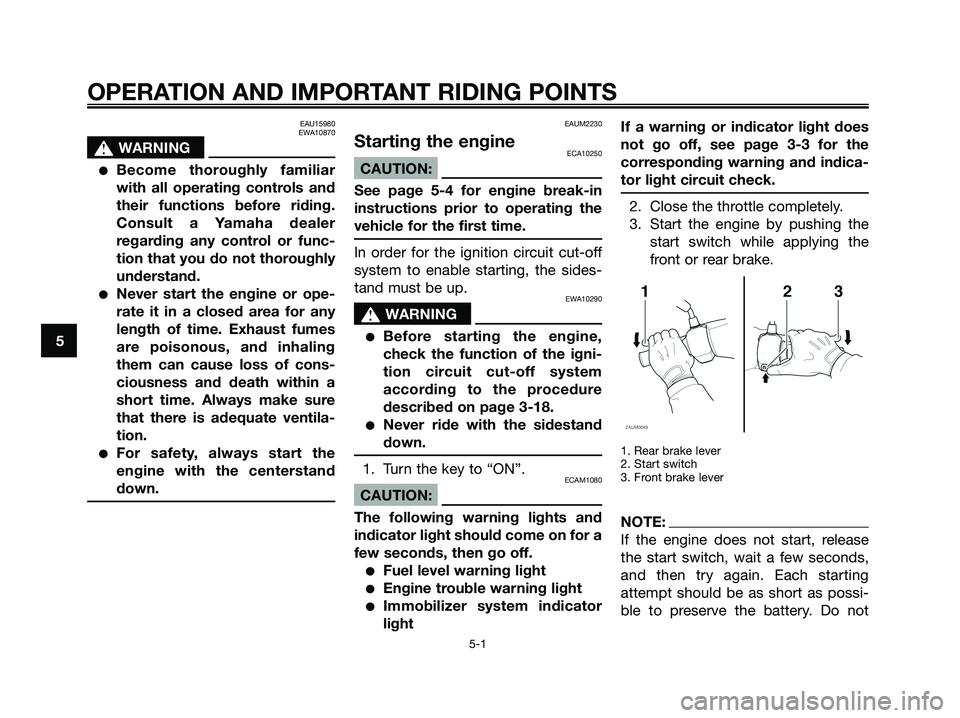
3. Start the engine by pushing the
start switch while applying the
front or rear brake.
1. Rear brake lever
2. Start switch
3. Front brake lever
NOTE:
If the engine does not start, release
the start switch, wait a few seconds,
and then try again. Each starting
attempt should be as short as possi-
ble to preserve the battery. Do not
OPERATION AND IMPORTANT RIDING POINTS
5-1
5
1B9-F8199-E2.qxd 13/11/07 12:18 Página 38
Page 85 of 88

INDEX
AAcceleration and deceleration ...................5-2
Air filter and V-belt case air filter
elements ................................................6-15
Anti-theft alarm (optional) ..........................3-9
Auxiliary light bulb, replacing ...................6-32
BBattery......................................................6-26
Brake fluid level, checking .......................6-21
Brake fluid, changing ...............................6-22
Brake lever, front ......................................3-10
Brake lever, rear .......................................3-11
Brake levers, lubricating ..........................6-23
Braking .......................................................5-3
CCables, checking and lubricating ............6-23
Care............................................................7-1
Catalytic converters .................................3-13
Centerstand and sidestand, checking
and lubricating .......................................6-24
Coolant.....................................................6-14
Coolant temperature gauge .......................3-5
Cowlings and panel, removing and
installing ...................................................6-7
DDimmer switch ...........................................3-9
Display, multi-function ...............................3-6
EEngine break-in ..........................................5-4
Engine oil .................................................6-10
Engine trouble warning light ......................3-3
FFinal transmission oil ...............................6-13
Front and rear brake lever free play.........6-20Front and rear brake pads, checking ......6-21
Front fork, checking .................................6-24
Fuel ..........................................................3-12
Fuel consumption, tips for reducing ..........5-3
Fuel gauge .................................................3-5
Fuel level warning light ..............................3-3
Fuel tank cap ...........................................3-11
Fuses, replacing .......................................6-27
HHandlebar switches ...................................3-9
Hazard switch ............................................3-9
Headlight bulb, replacing .........................6-29
High beam indicator light...........................3-3
Horn switch ................................................3-9
I
Identification numbers ...............................9-1
Ignition circuit cut-off system ..................3-18
Immobilizer system ....................................3-1
Immobilizer system indicator light .............3-3
Indicator and warning lights ......................3-3
KKey identification number ..........................9-1
LLicense plate light bulb, replacing ...........6-32
MMain switch/steering lock ..........................3-2
Matte color, caution ...................................7-4
Model label ................................................9-2
PParking .......................................................5-4
Part locations .............................................2-1
Periodic maintenance and lubrication
chart .........................................................6-3
Pre-operation check list .............................4-2
SSafe-riding points.......................................1-1
Safety information ......................................1-1
Seat ..........................................................3-14
Self-diagnosis device.................................3-4
Shock absorber assemblies, adjusting....3-17
Sidestand .................................................3-18
Spark plug, checking .................................6-9
Specifications.............................................8-1
Speedometer .............................................3-4
Start switch ................................................3-9
Starting off .................................................5-2
Starting the engine.....................................5-1
Steering, checking ...................................6-25
Storage.......................................................7-3
Storage compartment (front) ...................3-15
Storage compartment (rear) .....................3-16
Storage compartments ............................3-14
TTail/brake light bulb or rear turn signal
light bulb, replacing ...............................6-30
Throttle cable free play, adjusting ............6-17
Throttle grip and cable, checking and
lubricating ..............................................6-23
Tires .........................................................6-18
Tool kit ........................................................6-1
Troubleshooting .......................................6-32
Troubleshooting charts ............................6-33
Turn signal indicator lights .........................3-3
Turn signal light bulb (front), replacing ....6-30
Turn signal switch ......................................3-9
VValve clearance ........................................6-17
Vehicle identification number .....................9-1
1B9-F8199-E2.qxd 13/11/07 12:18 Página 85