YAMAHA XMAX 125 2017 Workshop Manual
Manufacturer: YAMAHA, Model Year: 2017, Model line: XMAX 125, Model: YAMAHA XMAX 125 2017Pages: 96, PDF Size: 8.13 MB
Page 51 of 96

Periodic maintenance and adjustment
6-5
6
14Front brake lever
pivot shaft• Lubricate with silicone grease.√√√√√
15Rear brake lever
pivot shaft• Lubricate with silicone grease.√√√√√
16Sidestand, center-
stand• Check operation.
• Lubricate with lithium-soap-
based grease.√√√√√
17*Sidestand switch• Check operation and replace if
necessary.√√√√√√
18*Front fork• Check operation and for oil leak-
age.
• Replace if necessary.√√√√
19*Shock absorber
assemblies• Check operation and for oil leak-
age.
• Replace if necessary.√√√√
20 Engine oil• Change (warm engine before
draining).At the initial interval and when
the oil change indicator flashes
or comes on
• Check oil level and vehicle for oil
leakage.Every 3000 km (1800 mi)
21Engine oil filter el-
ement• Replace.√√√
22*Final transmission
oil• Check vehicle for oil leakage.√√√√√
• Change.√√√
23*Cooling system• Check coolant level and vehicle
for coolant leakage.√√√√√
• Change. Every 3 years
24*V-belt• Replace.When the V-belt replacement
indicator flashes [every 18000
km (10500 mi)]
25*Front and rear
brake switches• Check operation.√√√√√√
26*Moving parts and
cables• Lubricate.√√√√√ NO. ITEM
X 1000 km CHECK OR
MAINTENANCE JOB
X 1000 mi
ODOMETER
READING
ANNUAL CHECK
16121824
0.63.5710.514
U2DME3E0.book Page 5 Friday, June 10, 2016 2:25 PM
Page 52 of 96
Periodic maintenance and adjustment
6-6
6
EAU72780
TIP
Engine air filter and V-belt air filters
• This model’s engine air filter is equipped with a disposable oil-coated pa-
per element, which must not be cleaned with compressed air to avoid
damaging it.
• The engine air filter element needs to be replaced and the V-belt air filter
elements need to be serviced more frequently when riding in unusually wet
or dusty areas.
Hydraulic brake service
• After disassembling the brake master cylinders and calipers, always
change the fluid. Regularly check the brake fluid levels and fill the reser-
voirs as required.
• Every two years replace the internal components of the brake master cyl-
inders and calipers, and change the brake fluid.
• Replace the brake hoses every four years and if cracked or damaged.
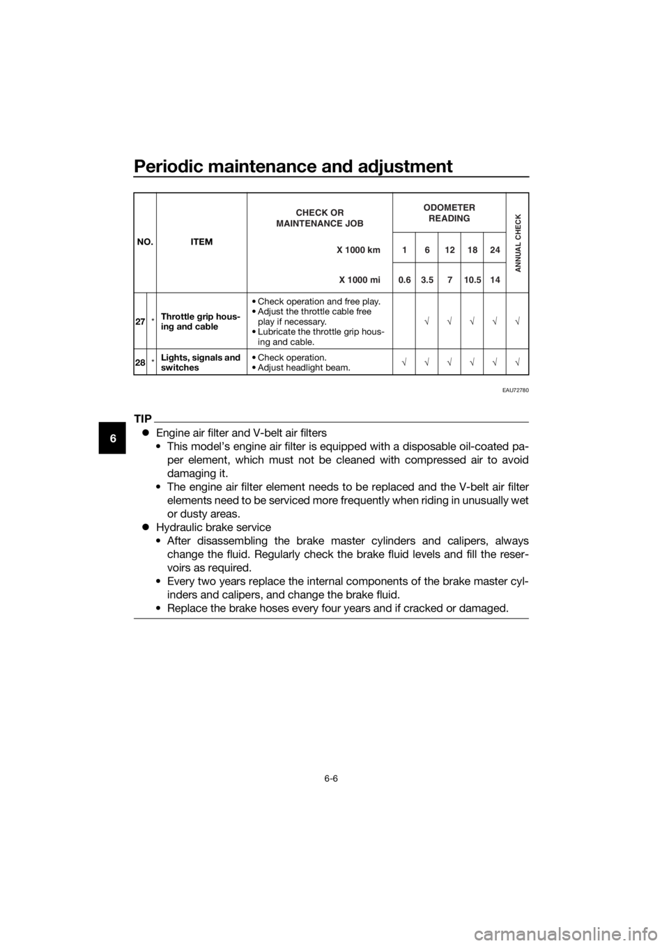
27*Throttle grip hous-
ing and cable• Check operation and free play.
• Adjust the throttle cable free
play if necessary.
• Lubricate the throttle grip hous-
ing and cable.√√√√√
28*Lights, signals and
switches• Check operation.
• Adjust headlight beam.√√√√√√ NO. ITEM
X 1000 km CHECK OR
MAINTENANCE JOB
X 1000 miODOMETER
READING
ANNUAL CHECK
16121824
0.6 3.5 7 10.5 14
U2DME3E0.book Page 6 Friday, June 10, 2016 2:25 PM
Page 53 of 96
Periodic maintenance and adjustment
6-7
6
EAU18773
Removing and installing pan-
els
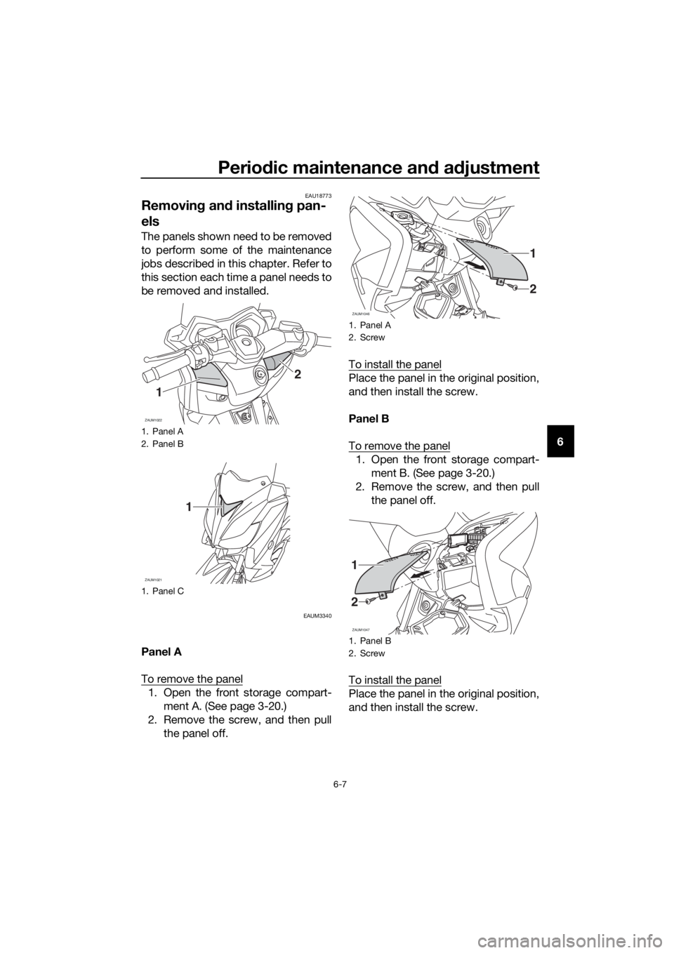
The panels shown need to be removed
to perform some of the maintenance
jobs described in this chapter. Refer to
this section each time a panel needs to
be removed and installed.
EAUM3340
Panel A
To remove the panel
1. Open the front storage compart-
ment A. (See page 3-20.)
2. Remove the screw, and then pull
the panel off.To install the panel
Place the panel in the original position,
and then install the screw.
Panel B
To remove the panel
1. Open the front storage compart-
ment B. (See page 3-20.)
2. Remove the screw, and then pull
the panel off.
To install the panel
Place the panel in the original position,
and then install the screw.
1. Panel A
2. Panel B
1. Panel C
ZAUM1022
1
2
ZAUM1021
1
1. Panel A
2. Screw
1. Panel B
2. Screw
ZAUM1046
1
2
ZAUM1047
1
2
U2DME3E0.book Page 7 Friday, June 10, 2016 2:25 PM
Page 54 of 96
Periodic maintenance and adjustment
6-8
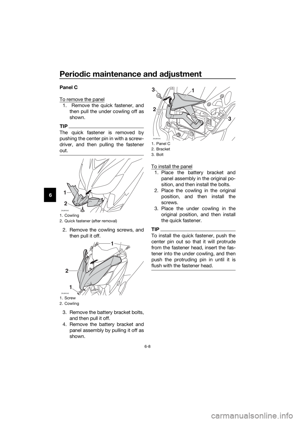
6Panel C
To remove the panel
1. Remove the quick fastener, and
then pull the under cowling off as
shown.
TIP
The quick fastener is removed by
pushing the center pin in with a screw-
driver, and then pulling the fastener
out.
2. Remove the cowling screws, and
then pull it off.
3. Remove the battery bracket bolts,
and then pull it off.
4. Remove the battery bracket and
panel assembly by pulling it off as
shown.To install the panel
1. Place the battery bracket and
panel assembly in the original po-
sition, and then install the bolts.
2. Place the cowling in the original
position, and then install the
screws.
3. Place the under cowling in the
original position, and then install
the quick fastener.
TIP
To install the quick fastener, push the
center pin out so that it will protrude
from the fastener head, insert the fas-
tener into the under cowling, and then
push the protruding pin in until it is
flush with the fastener head.
1. Cowling
2. Quick fastener (after removal)
1. Screw
2. Cowling
ZAUM1042
1
2
ZAUM1043
2
1
1
1. Panel C
2. Bracket
3. Bolt
ZAUM1045
13
2
3
U2DME3E0.book Page 8 Friday, June 10, 2016 2:25 PM
Page 55 of 96
Periodic maintenance and adjustment
6-9
6
EAUM3360
Checking the spark plug
The spark plug is an important engine
component, which is easy to check.
Since heat and deposits will cause any
spark plug to slowly erode, the spark
plug should be removed and checked
in accordance with the periodic main-
tenance and lubrication chart. In addi-
tion, the condition of the spark plug
can reveal the condition of the engine.
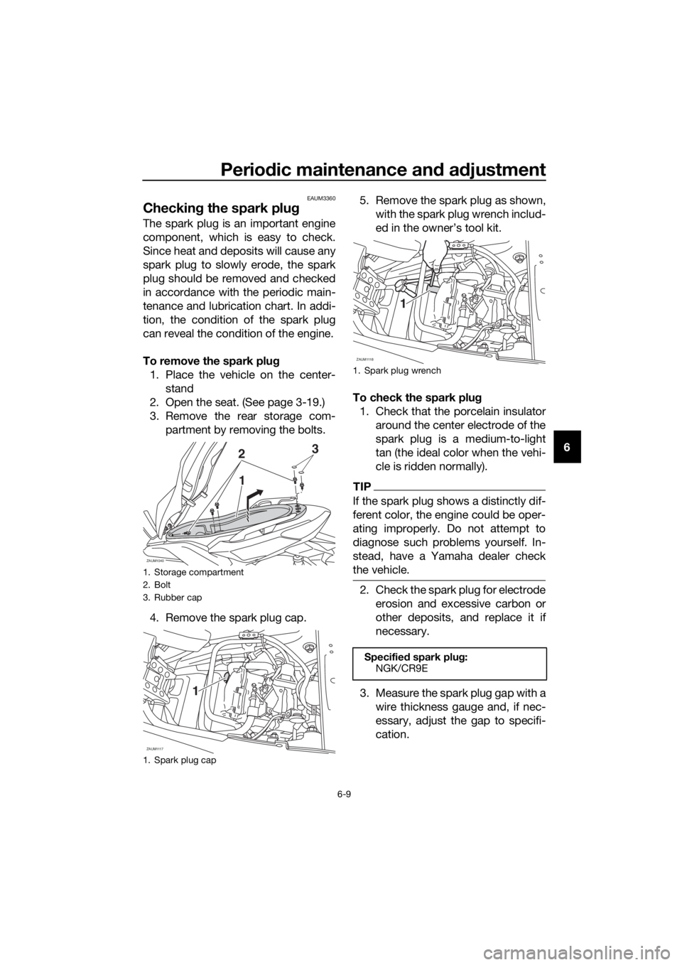
To remove the spark plug
1. Place the vehicle on the center-
stand
2. Open the seat. (See page 3-19.)
3. Remove the rear storage com-
partment by removing the bolts.
4. Remove the spark plug cap.5. Remove the spark plug as shown,
with the spark plug wrench includ-
ed in the owner’s tool kit.
To check the spark plug
1. Check that the porcelain insulator
around the center electrode of the
spark plug is a medium-to-light
tan (the ideal color when the vehi-
cle is ridden normally).
TIP
If the spark plug shows a distinctly dif-
ferent color, the engine could be oper-
ating improperly. Do not attempt to
diagnose such problems yourself. In-
stead, have a Yamaha dealer check
the vehicle.
2. Check the spark plug for electrode
erosion and excessive carbon or
other deposits, and replace it if
necessary.
3. Measure the spark plug gap with a
wire thickness gauge and, if nec-
essary, adjust the gap to specifi-
cation.
1. Storage compartment
2. Bolt
3. Rubber cap
1. Spark plug cap
ZAUM1040
23
1
ZAUM1117
1
1. Spark plug wrench
Specified spark plug:
NGK/CR9E
ZAUM1118
1
U2DME3E0.book Page 9 Friday, June 10, 2016 2:25 PM
Page 56 of 96
Periodic maintenance and adjustment
6-10
6To install the spark plug
1. Clean the surface of the spark
plug gasket and its mating sur-
face, and then wipe off any grime
from the spark plug threads.
2. Install the spark plug with the
spark plug wrench, and then tight-
en it to the specified torque.
TIP
If a torque wrench is not available
when installing a spark plug, a good
estimate of the correct torque is 1/4…
1/2 turn past finger tight. However, the
spark plug should be tightened to the
specified torque as soon as possible.
3. Install the spark plug cap.
4. Place the rear storage compart-
ment in the original position and
install the bolts.
5. Close the seat.
EAUM3332
Engine oil
The engine oil level should be checked
before each ride. In addition, the oil
must be changed at the intervals spec-
ified in the periodic maintenance and
lubrication chart and when the service
indicator light comes on.
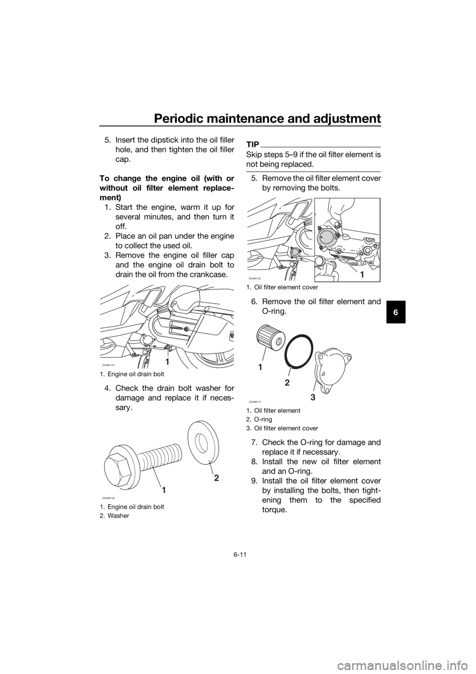
To check the engine oil level
1. Place the scooter on the center-
stand. A slight tilt to the side can
result in a false reading.
2. Start the engine, warm it up for
several minutes, and then turn it
off.
3. Wait a few minutes until the oil set-
tles, remove the oil filler cap, wipe
the dipstick clean, insert it back
into the oil filler hole (without
screwing it in), and then remove it
again to check the oil level.
TIP
The engine oil should be between the
minimum and maximum level marks.
4. If the engine oil is below the mini-
mum level mark, add sufficient oil
of the recommended type to raise
it to the correct level.
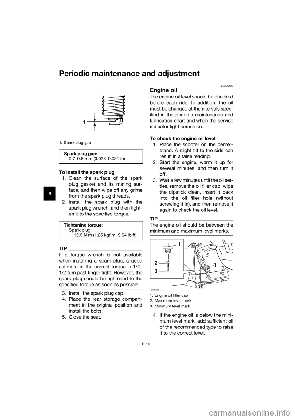
1. Spark plug gap
Spark plug gap:
0.7–0.8 mm (0.028–0.031 in)
Tightening torque:
Spark plug:
12.5 N·m (1.25 kgf·m, 9.04 lb·ft)
1
1. Engine oil filler cap
2. Maximum level mark
3. Minimum level mark
1
3
2
1
ZAUM0685
U2DME3E0.book Page 10 Friday, June 10, 2016 2:25 PM
Page 57 of 96
Periodic maintenance and adjustment
6-11
6 5. Insert the dipstick into the oil filler
hole, and then tighten the oil filler
cap.
To change the engine oil (with or
without oil filter element replace-
ment)
1. Start the engine, warm it up for
several minutes, and then turn it
off.
2. Place an oil pan under the engine
to collect the used oil.
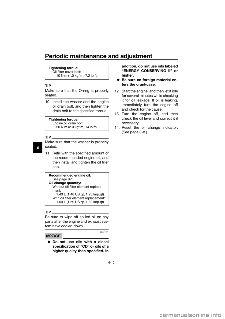
3. Remove the engine oil filler cap
and the engine oil drain bolt to
drain the oil from the crankcase.
4. Check the drain bolt washer for
damage and replace it if neces-
sary.
TIP
Skip steps 5…9 if the oil filter element is
not being replaced.
5. Remove the oil filter element cover
by removing the bolts.
6. Remove the oil filter element and
O-ring.
7. Check the O-ring for damage and
replace it if necessary.
8. Install the new oil filter element
and an O-ring.
9. Install the oil filter element cover
by installing the bolts, then tight-
ening them to the specified
torque.
1. Engine oil drain bolt
1. Engine oil drain bolt
2. Washer
ZAUM11191
1
2
ZAUM0129
1. Oil filter element cover
1. Oil filter element
2. O-ring
3. Oil filter element cover
ZAUM11201
1
2
3
ZAUM0712
U2DME3E0.book Page 11 Friday, June 10, 2016 2:25 PM
Page 58 of 96
Periodic maintenance and adjustment
6-12
6
TIP
Make sure that the O-ring is properly
seated.
10. Install the washer and the engine
oil drain bolt, and then tighten the
drain bolt to the specified torque.
TIP
Make sure that the washer is properly
seated.
11. Refill with the specified amount of
the recommended engine oil, and
then install and tighten the oil filler
cap.
TIP
Be sure to wipe off spilled oil on any
parts after the engine and exhaust sys-
tem have cooled down.
NOTICE
ECA11671
Do not use oils with a diesel
specification of “CD” or oils of a
higher quality than specified. Inaddition, do not use oils labeled
“ENERGY CONSERVING II” or
higher.
Be sure no foreign material en-
ters the crankcase.
12. Start the engine, and then let it idle
for several minutes while checking
it for oil leakage. If oil is leaking,
immediately turn the engine off
and check for the cause.
13. Turn the engine off, and then
check the oil level and correct it if
necessary.
14. Reset the oil change indicator.
(See page 3-8.)
Tightening torque:
Oil filter cover bolt:
10 N·m (1.0 kgf·m, 7.2 lb·ft)
Tightening torque:
Engine oil drain bolt:
20 N·m (2.0 kgf·m, 14 lb·ft)
Recommended engine oil:
See page 8-1.
Oil change quantity:
Without oil filter element replace-
ment:
1.40 L (1.48 US qt, 1.23 Imp.qt)
With oil filter element replacement:
1.50 L (1.59 US qt, 1.32 Imp.qt)
U2DME3E0.book Page 12 Friday, June 10, 2016 2:25 PM
Page 59 of 96
Periodic maintenance and adjustment
6-13
6
EAU20067
Final transmission oil
The final transmission case must be
checked for oil leakage before each
ride. If any leakage is found, have a
Yamaha dealer check and repair the
scooter. In addition, the final transmis-
sion oil must be changed as follows at
the intervals specified in the periodic
maintenance and lubrication chart.
1. Start the engine, warm up the final
transmission oil by riding the
scooter for several minutes, and
then stop the engine.
2. Place the scooter on the center-
stand.
3. Place an oil pan under the final
transmission case to collect the
used oil.
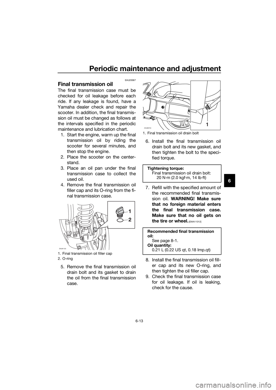
4. Remove the final transmission oil
filler cap and its O-ring from the fi-
nal transmission case.
5. Remove the final transmission oil
drain bolt and its gasket to drain
the oil from the final transmission
case.6. Install the final transmission oil
drain bolt and its new gasket, and
then tighten the bolt to the speci-
fied torque.
7. Refill with the specified amount of
the recommended final transmis-
sion oil. WARNING! Make sure
that no foreign material enters
the final transmission case.
Make sure that no oil gets on
the tire or wheel.
[EWA11312]
8. Install the final transmission oil fill-
er cap and its new O-ring, and
then tighten the oil filler cap.
9. Check the final transmission case
for oil leakage. If oil is leaking,
check for the cause.
1. Final transmission oil filler cap
2. O-ring
ZAUM1123
1. Final transmission oil drain bolt
Tightening torque:
Final transmission oil drain bolt:
20 N·m (2.0 kgf·m, 14 lb·ft)
Recommended final transmission
oil:
See page 8-1.
Oil quantity:
0.21 L (0.22 US qt, 0.18 Imp.qt)
ZAUM07031
U2DME3E0.book Page 13 Friday, June 10, 2016 2:25 PM
Page 60 of 96
Periodic maintenance and adjustment
6-14
6
EAU20071
Coolant
The coolant level should be checked
before each ride. In addition, the cool-
ant must be changed at the intervals
specified in the periodic maintenance
and lubrication chart.
EAUM3045To check the coolant level
1. Place the vehicle on a level sur-
face and hold it in an upright posi-
tion.
2. Open the front storage compart-
ment A. (See page 3-20.)
TIP
The coolant level must be
checked on a cold engine since
the level varies with engine tem-
perature.
Make sure that the vehicle is posi-
tioned straight up when checking
the coolant level. A slight tilt to the
side can result in a false reading.
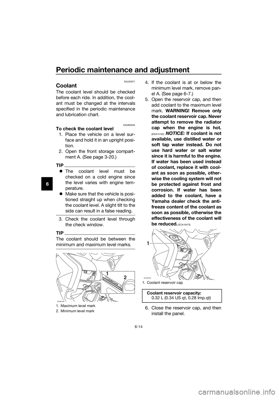
3. Check the coolant level through
the check window.
TIP
The coolant should be between the
minimum and maximum level marks.
4. If the coolant is at or below the
minimum level mark, remove pan-
el A. (See page 6-7.)
5. Open the reservoir cap, and then
add coolant to the maximum level
mark. WARNING! Remove only
the coolant reservoir cap. Never
attempt to remove the radiator
cap when the engine is hot.
[EWA15162] NOTICE: If coolant is not
available, use distilled water or
soft tap water instead. Do not
use hard water or salt water
since it is harmful to the engine.
If water has been used instead
of coolant, replace it with cool-
ant as soon as possible, other-
wise the cooling system will not
be protected against frost and
corrosion. If water has been
added to the coolant, have a
Yamaha dealer check the anti-
freeze content of the coolant as
soon as possible, otherwise the
effectiveness of the coolant will
be reduced.
[ECA10473]
6. Close the reservoir cap, and then
install the panel.1. Maximum level mark
2. Minimum level mark
ZAUM1029
2 1Coolant LevelCoolant L
evelH
ighH
igh
LowLo
w1. Coolant reservoir cap
Coolant reservoir capacity:
0.32 L (0.34 US qt, 0.28 Imp.qt)
ZAUM1030
1
U2DME3E0.book Page 14 Friday, June 10, 2016 2:25 PM