key battery YAMAHA XMAX 250 2010 Owners Manual
[x] Cancel search | Manufacturer: YAMAHA, Model Year: 2010, Model line: XMAX 250, Model: YAMAHA XMAX 250 2010Pages: 84, PDF Size: 5.4 MB
Page 18 of 84

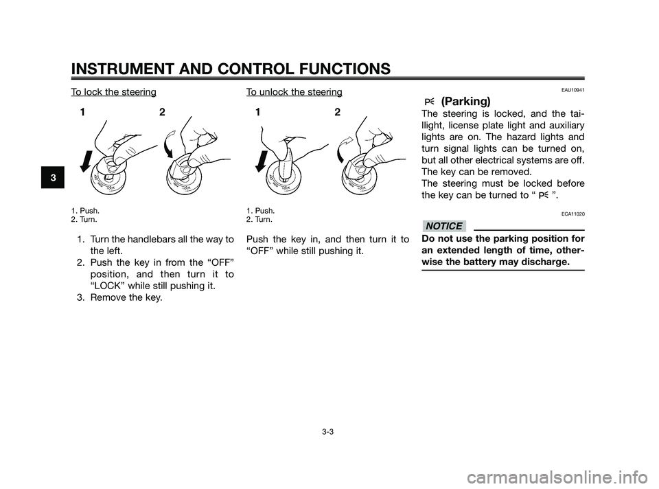
To lock the steering
1. Push.
2. Turn.
1. Turn the handlebars all the way tothe left.
2. Push the key in from the “OFF” position, and then turn it to
“LOCK” while still pushing it.
3. Remove the key. T
o unlock the steering
1. Push.
2. Turn.
Push the key in, and then turn it to
“OFF” while still pushing it.
EAU10941
(Parking)
The steering is locked, and the tai-
llight, license plate light and auxiliary
lights are on. The hazard lights and
turn signal lights can be turned on,
but all other electrical systems are off.
The key can be removed.
The steering must be locked before
the key can be turned to “ ”.
ECA11020
Do not use the parking position for
an extended length of time, other-
wise the battery may discharge.
NOTICE
INSTRUMENT AND CONTROL FUNCTIONS
3-3
3
37P-F8199-E0 18/9/09 14:54 Página 18
Page 26 of 84

EAU12348
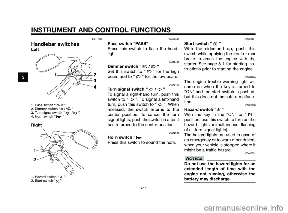
Handlebar switches
Left
1. Pass switch “PASS”
2. Dimmer switch “ / ”
3. Turn signal switch “ / ”
4. Horn switch “ ”
Right
1. Hazard switch “ ”
2. Start switch “ ”
EAU12350
Pass switch “PASS”
Press this switch to flash the head-
light.
EAU12400
Dimmer switch “ / ”
Set this switch to “ ” for the high
beam and to “ ” for the low beam.
EAU12460
Turn signal switch “ / ”
To signal a right-hand turn, push this
switch to “ ”. To signal a left-hand
turn, push this switch to “ ”. When
released, the switch returns to the
center position. To cancel the turn
signal lights, push the switch in after it
has returned to the center position.
EAU12500
Horn switch “ ”
Press this switch to sound the horn.
EAU12721
Start switch “ ”
With the sidestand up, push this
switch while applying the front or rear
brake to crank the engine with the
starter. See page 5-1 for starting ins-
tructions prior to starting the engine.
EAU41700
The engine trouble warning light will
come on when the key is turned to
“ON” and the start switch is pushed,
but this does not indicate a malfunc-
tion.
EAU12733
Hazard switch “ ”
With the key in the “ON” or “ ”
position, use this switch to turn on the
hazard lights (simultaneous flashing
of all turn signal lights).
The hazard lights are used in case of
an emergency or to warn other drivers
when your vehicle is stopped where it
might be a traffic hazard.
ECA10061
Do not use the hazard lights for an
extended length of time with the
engine not running, otherwise the
battery may discharge.
NOTICE
INSTRUMENT AND CONTROL FUNCTIONS
3-11
3
37P-F8199-E0 18/9/09 14:54 Página 26
Page 66 of 84

To charge the battery
Have a Yamaha dealer charge the
battery as soon as possible if it seems
to have discharged. Keep in mind that
the battery tends to discharge more
quickly if the vehicle is equipped with
optional electrical accessories.
ECA16520
To charge a VRLA (Valve Regulated
Lead Acid) battery, a special (cons-
tant-voltage) battery charger is
required. Using a conventional bat-
tery charger will damage the bat-
tery. If you do not have access to a
constant-voltage battery charger,
have a Yamaha dealer charge your
battery.
To store the battery1. If the vehicle will not be used for more than one month, remove the
battery, fully charge it, and then
place it in a cool, dry place. NOTI-
CE: When removing the battery,
be sure the key is turned to
“OFF”, then disconnect the
negative lead before discon-
necting the positive lead.
[ECA16302]
2. If the battery will be stored for more than two months, check it
at least once a month and fully
charge it if necessary.
3. Fully charge the battery before installation.
4. After installation, make sure that the battery leads are properly
connected to the battery termi-
nals.
ECA16530
Always keep the battery charged.
Storing a discharged battery can
cause permanent battery damage.
EAUS1771
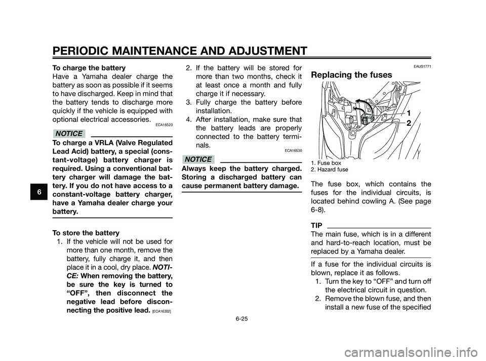
Replacing the fuses
1. Fuse box
2. Hazard fuse
The fuse box, which contains the
fuses for the individual circuits, is
located behind cowling A. (See page
6-8).
TIP
The main fuse, which is in a different
and hard-to-reach location, must be
replaced by a Yamaha dealer.
If a fuse for the individual circuits is
blown, replace it as follows.1. Turn the key to “OFF” and turn off the electrical circuit in question.
2. Remove the blown fuse, and then install a new fuse of the specified
NOTICE
NOTICE
PERIODIC MAINTENANCE AND ADJUSTMENT
6-25
6
37P-F8199-E0 18/9/09 14:54 Página 66
Page 82 of 84

AAcceleration and deceleration ...................5-2
Air filter and V-belt case air filter elements ................................................6-15
Auxiliary light bulb, replacing ...................6-28
BBattery......................................................6-24
Brake fluid level, checking .......................6-20
Brake fluid, changing ...............................6-21
Brake lever, front ......................................3-12
Brake lever, rear .......................................3-12
Brake levers, lubricating ..........................6-21
Braking .......................................................5-3
CCare............................................................7-1
Catalytic converters .................................3-14
Centerstand and sidestand, checking and lubricating .......................................6-22
Coolant.....................................................6-13
Cowling and panel, removing and installing ...................................................6-8
DDimmer switch .........................................3-11
EEngine break-in ..........................................5-4
Engine oil .................................................6-10
Engine trouble warning light ......................3-4
FFinal transmission oil ...............................6-12
Front and rear brake lever free play.........6-18
Front and rear brake pads, checking ......6-19
Front fork, checking .................................6-23
Fuel ..........................................................3-13
Fuel consumption, tips for reducing ..........5-3 Fuel tank cap ...........................................3-12
Fuses, replacing .......................................6-25
HHandlebar switches .................................3-11
Hazard switch ..........................................3-11
Headlight bulb, replacing .........................6-26
High beam indicator light...........................3-4
Horn switch ..............................................3-11
IIdentification numbers ...............................9-1
Ignition circuit cut-off system ..................3-19
Immobilizer system ....................................3-1
Immobilizer system indicator light .............3-4
Indicator and warning lights ......................3-4
KKey identification number ..........................9-1
LLicense plate light bulb, replacing ...........6-28
MMain switch/steering lock ..........................3-2
Maintenance and lubrication, periodic ......6-4
Maintenance, emission control system .....6-3
Matte color, caution ...................................7-1
Model label ................................................9-2
Multi-function display ................................3-6
PParking .......................................................5-4
Part locations .............................................1-5
Pass switch ..............................................3-11
SSafe-riding points.......................................1-5
Safety information ......................................1-1
Seat ..........................................................3-15
Securing bracket ......................................3-15Shock absorber assemblies, adjusting....3-18
Sidestand .................................................3-18
Spark plug, checking .................................6-9
Specifications.............................................7-3
Speedometer .............................................3-5
Start switch ..............................................3-11
Starting off .................................................5-2
Starting the engine.....................................5-1
Steering, checking ...................................6-23
Storage.......................................................7-3
Storage compartments ............................3-16
TTachometer ................................................3-5
Tail/brake light bulb or rear turn signal
light bulb, replacing ...............................6-27
Throttle cable free play, checking ............6-16
Throttle grip and cable, checking and lubricating ..............................................6-21
Tires .........................................................6-16
Tool kit ........................................................6-2
Troubleshooting .......................................6-29
Troubleshooting charts ............................6-30
Turn signal indicator lights .........................3-4
Turn signal light bulb (front), replacing ................................................6-27
Turn signal switch ....................................3-11
VValve clearance ........................................6-16
Vehicle identification number .....................9-1
WWheel bearings, checking........................6-24
Wheels .....................................................6-18
INDEX
37P-F8199-E0 18/9/09 14:54 Página 82