service indicator YAMAHA XSR 700 XTRIBUTE 2021 Owners Manual
[x] Cancel search | Manufacturer: YAMAHA, Model Year: 2021, Model line: XSR 700 XTRIBUTE, Model: YAMAHA XSR 700 XTRIBUTE 2021Pages: 98, PDF Size: 3.92 MB
Page 36 of 98

Instrument and control functions
3-21
3
EAU47003
A djustin g the shock a bsorb er
assem blyThis shock absorber assembly is
equipped with a spring preload adjust-
ing ring.NOTICE
ECA10102
To avoi d d amag ing the mechanism,
d o not attempt to turn b eyond the
maximum or minimum setting s.Adjust the spring preload as follows.
Turn the adjusting ring in direction (a)
to increase the spring preload.
Turn the adjusting ring in direction (b)
to decrease the spring preload.
Align the appropriate notch in the
adjusting ring with the position in-
dicator on the shock absorber.
Use the special wrench and ex-
tension bar included in the tool kit
to make the adjustment.
WARNING
EWA10222
This shock a bsor ber assem bly con-
tains hi ghly pressurize d nitro gen
g as. Rea d an d un derstan d the fol-
lowin g information b efore handlin g
the shock a bsor ber assem bly.
Do not tamper with or attempt
to open the cylin der assem bly.
Do not su bject the shock a b-
sor ber assem bly to an open
flame or other hi gh heat source.
This may cause the unit to ex-
plo de due to excessive gas
pressure.
Do not deform or d amage the
cylin der in any way. Cylin der
d amag e will result in poor
d ampin g performance.
Do not d ispose of a damag ed or
worn-out shock a bsor ber as-
sem bl
y yourself. Take the shock
a b sor ber assem bly to a Yamaha
d ealer for any service.
1. Extension bar
2. Special wrench
3. Spring preload adjusting ring
4. Position indicatorSprin g preloa d setting :
Minimum (soft): 1
Standard: 3
Maximum (hard):
9
7
6
9
8
5
4
3
2
1
3
(a)(b)
2
1
4
UBJXE0E0.book Page 21 Tuesday, January 5, 2021 10:42 AM
Page 66 of 98

Periodic maintenance an d a djustment
6-20
6 b
rakin g performance, which may re-
sult in loss of control and an acci-
d ent.
EAU36505
Brake li ght switchesThe brake light should come on just
before braking takes effect. The brake
light is activated by switches connect-
ed to the brake lever and brake pedal.
Since the brake light switches are
components of the anti-lock brake sys-
tem, they should only be serviced by a
Yamaha dealer.
EAU22393
Checkin g the front an d rear
b rake pa dsThe front and rear brake pads must be
checked for wear at the intervals spec-
ified in the periodic maintenance and
lubrication chart.
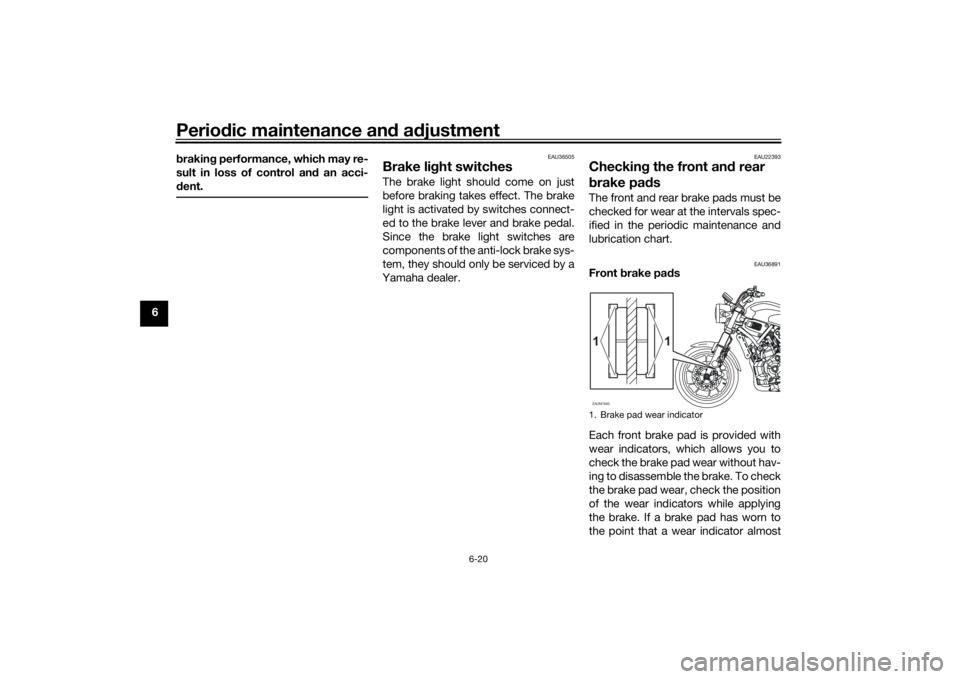
EAU36891
Front brake pa ds
Each front brake pad is provided with
wear indicators, which allows you to
check the brake pad wear without hav-
ing to disassemble the brake. To check
the brake pad wear, check the position
of the wear indicators while applying
the brake. If a brake pad has worn to
the point that a wear indicator almost1. Brake pad wear indicatorZAUM1845
1
1
UBJXE0E0.book Page 20 Tuesday, January 5, 2021 10:42 AM