xvs 1100 a YAMAHA XVS1100A 2000 User Guide
[x] Cancel search | Manufacturer: YAMAHA, Model Year: 2000, Model line: XVS1100A, Model: YAMAHA XVS1100A 2000Pages: 104, PDF Size: 14.79 MB
Page 23 of 104
INSTRUMENT AND CONTROL FUNCTIONS
3-6
3
EAU00157
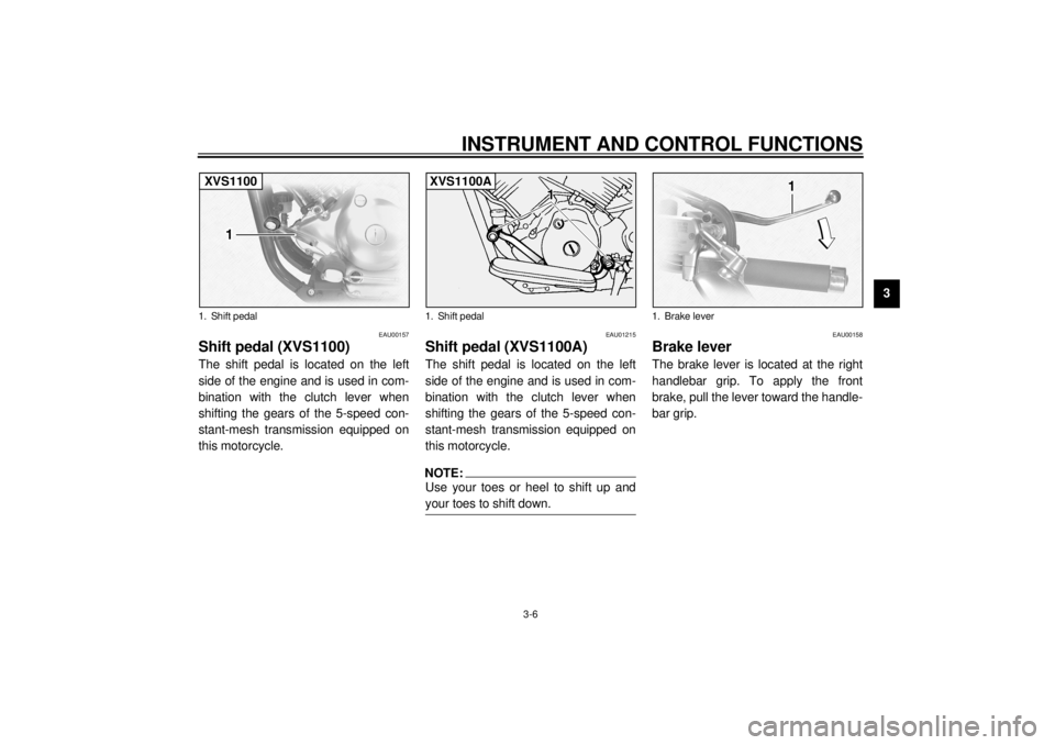
Shift pedal (XVS1100)The shift pedal is located on the left
side of the engine and is used in com-
bination with the clutch lever when
shifting the gears of the 5-speed con-
stant-mesh transmission equipped on
this motorcycle.
EAU01215
Shift pedal (XVS1100A)The shift pedal is located on the left
side of the engine and is used in com-
bination with the clutch lever when
shifting the gears of the 5-speed con-
stant-mesh transmission equipped on
this motorcycle.NOTE:Use your toes or heel to shift up and
your toes to shift down.
EAU00158
Brake lever The brake lever is located at the right
handlebar grip. To apply the front
brake, pull the lever toward the handle-
bar grip.
1. Shift pedalXVS1100
1. Shift pedalXVS1100A
1. Brake lever
E_5KS.book Page 6 Monday, August 21, 2000 10:48 AM
Page 24 of 104
INSTRUMENT AND CONTROL FUNCTIONS
3-7
3
EAU00162
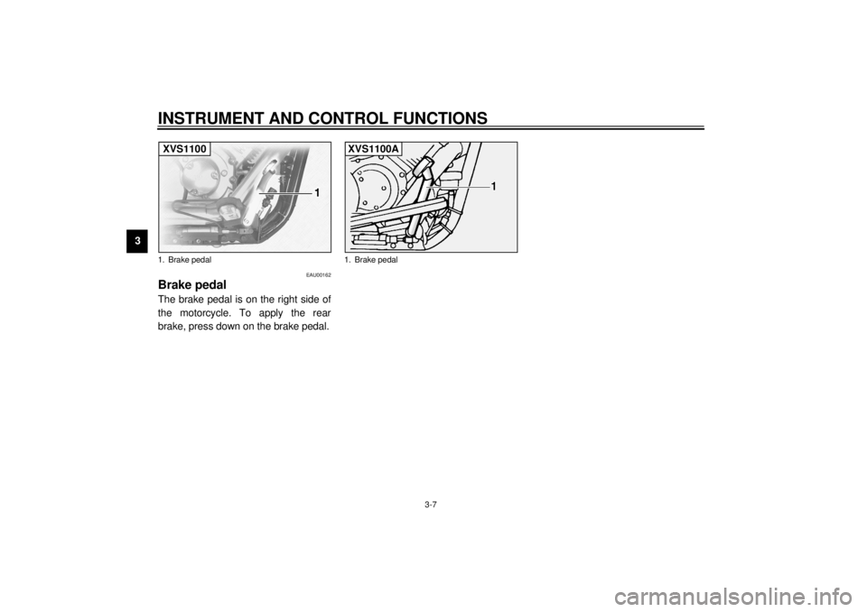
Brake pedal The brake pedal is on the right side of
the motorcycle. To apply the rear
brake, press down on the brake pedal.1. Brake pedalXVS1100
1. Brake pedalXVS1100A
E_5KS.book Page 7 Monday, August 21, 2000 10:48 AM
Page 28 of 104
INSTRUMENT AND CONTROL FUNCTIONS
3-11
3
EAU01710
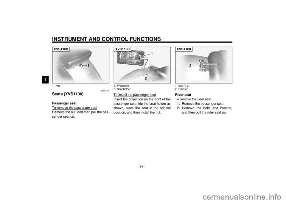
Seats (XVS1100) Passenger seat
To remove the passenger seatRemove the nut, and then pull the pas-
senger seat up.To install the passenger seat
Insert the projection on the front of the
passenger seat into the seat holder as
shown, place the seat in the original
position, and then install the nut.Rider seat
To remove the rider seat
1. Remove the passenger seat.
2. Remove the bolts and bracket,
and then pull the rider seat up.
1. NutXVS1100
1. Projection
2. Seat holderXVS1100
1. Bolt (´ 2)
2. BracketXVS1100
E_5KS.book Page 11 Monday, August 21, 2000 10:48 AM
Page 29 of 104
INSTRUMENT AND CONTROL FUNCTIONS
3-12
3
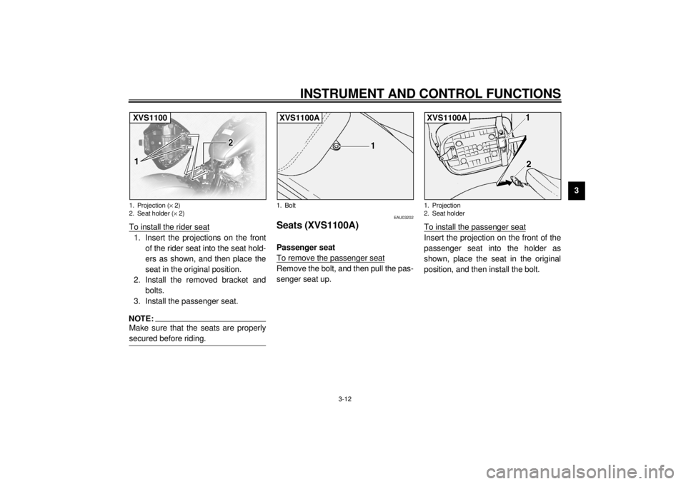
To install the rider seat
1. Insert the projections on the front
of the rider seat into the seat hold-
ers as shown, and then place the
seat in the original position.
2. Install the removed bracket and
bolts.
3. Install the passenger seat.NOTE:@ Make sure that the seats are properly
secured before riding. @
EAU03202
Seats (XVS1100A)Passenger seat
To remove the passenger seatRemove the bolt, and then pull the pas-
senger seat up.To install the passenger seat
Insert the projection on the front of the
passenger seat into the holder as
shown, place the seat in the original
position, and then install the bolt.
1. Projection (´ 2)
2. Seat holder (´ 2)XVS1100
1. BoltXVS1100A
1. Projection
2. Seat holderXVS1100A
E_5KS.book Page 12 Monday, August 21, 2000 10:48 AM
Page 30 of 104
INSTRUMENT AND CONTROL FUNCTIONS
3-13
3
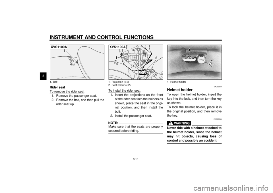
Rider seat
To remove the rider seat
1. Remove the passenger seat.
2. Remove the bolt, and then pull the
rider seat up.To install the rider seat
1. Insert the projections on the front
of the rider seat into the holders as
shown, place the seat in the origi-
nal position, and then install the
bolt.
2. Install the passenger seat.NOTE:@ Make sure that the seats are properly
secured before riding. @
EAU00260
Helmet holder To open the helmet holder, insert the
key into the lock, and then turn the key
as shown.
To lock the helmet holder, place it in
the original position, and then remove
the key.
EW000030
WARNING
@ Never ride with a helmet attached to
the helmet holder, since the helmet
may hit objects, causing loss of
control and possibly an accident. @
1. BoltXVS1100A
1. Projection (´ 2)
2. Seat holder (´ 2)XVS1100A
1. Helmet holder
E_5KS.book Page 13 Monday, August 21, 2000 10:48 AM
Page 32 of 104
INSTRUMENT AND CONTROL FUNCTIONS
3-15
3
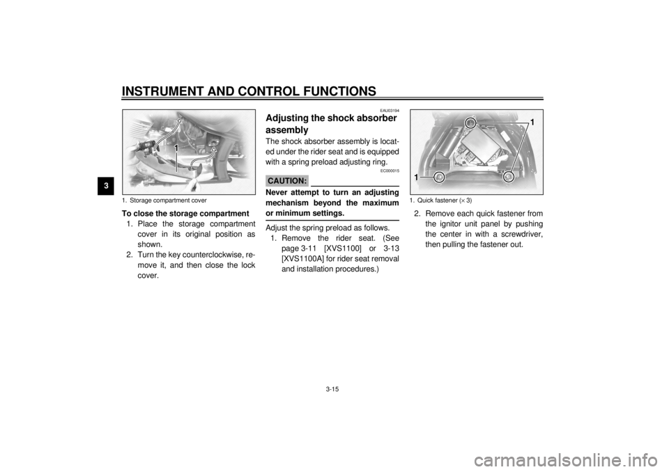
To close the storage compartment
1. Place the storage compartment
cover in its original position as
shown.
2. Turn the key counterclockwise, re-
move it, and then close the lock
cover.
EAU03194
Adjusting the shock absorber
assembly The shock absorber assembly is locat-
ed under the rider seat and is equipped
with a spring preload adjusting ring.
EC000015
CAUTION:@ Never attempt to turn an adjusting
mechanism beyond the maximum
or minimum settings. @Adjust the spring preload as follows.
1. Remove the rider seat. (See
page 3-11 [XVS1100] or 3-13
[XVS1100A] for rider seat removal
and installation procedures.)2. Remove each quick fastener from
the ignitor unit panel by pushing
the center in with a screwdriver,
then pulling the fastener out.
1. Storage compartment cover
1. Quick fastener (´ 3)
E_5KS.book Page 15 Monday, August 21, 2000 10:48 AM
Page 33 of 104
INSTRUMENT AND CONTROL FUNCTIONS
3-16
3
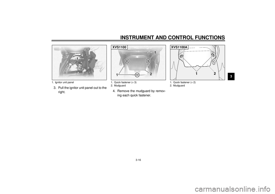
3. Pull the ignitor unit panel out to the
right.4. Remove the mudguard by remov-
ing each quick fastener.
1. Ignitor unit panel
1. Quick fastener (´ 3)
2. MudguardXVS1100
1. Quick fastener (´ 2)
2. MudguardXVS1100A
E_5KS.book Page 16 Monday, August 21, 2000 10:48 AM
Page 46 of 104
OPERATION AND IMPORTANT RIDING POINTS
5-3
5
EAU01258
Starting a warm engine Follow the same procedure as for start-
ing a cold engine with the exception
that the starter (choke) is not required
when the engine is warm.
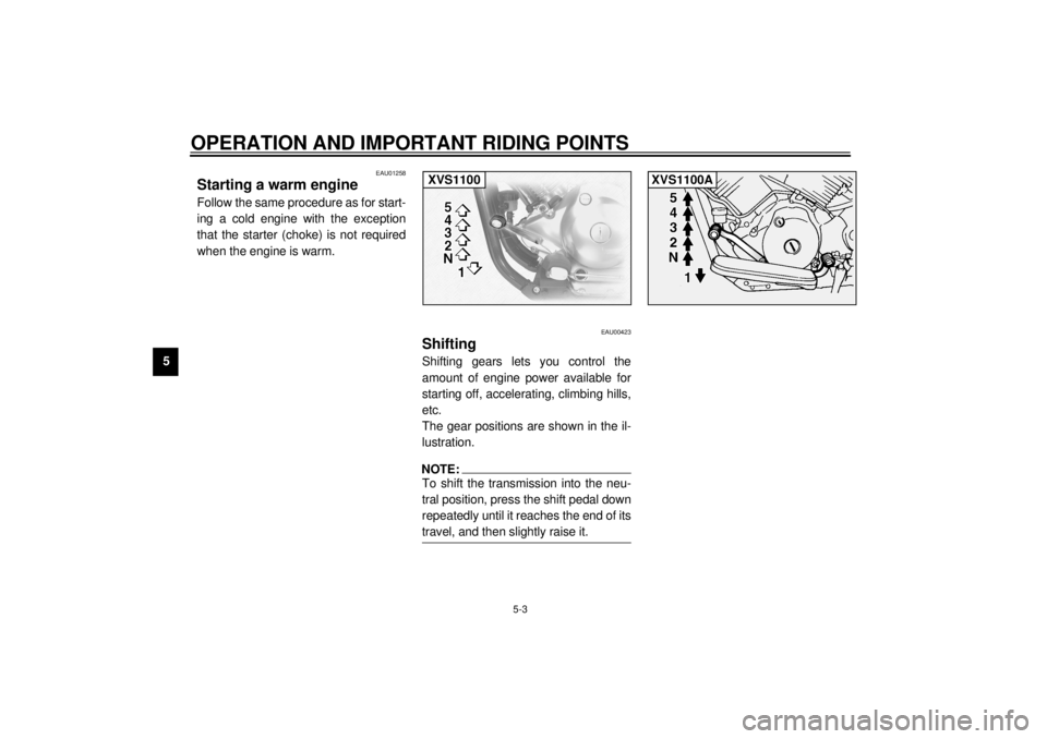
EAU00423
Shifting Shifting gears lets you control the
amount of engine power available for
starting off, accelerating, climbing hills,
etc.
The gear positions are shown in the il-
lustration.NOTE:@ To shift the transmission into the neu-
tral position, press the shift pedal down
repeatedly until it reaches the end of its
travel, and then slightly raise it. @XVS1100
XVS1100A
E_5KS.book Page 3 Monday, August 21, 2000 10:48 AM
Page 63 of 104
PERIODIC MAINTENANCE AND MINOR REPAIR
6-14
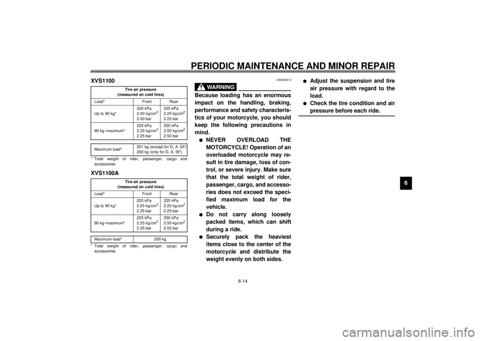
6 XVS1100
CE-01E
CE-07EXVS1100ACE-01E
CE-07EEWA00012
WARNING
@ Because loading has an enormous
impact on the handling, braking,
performance and safety characteris-
tics of your motorcycle, you should
keep the following precautions in
mind. l
NEVER OVERLOAD THE
MOTORCYCLE! Operation of an
overloaded motorcycle may re-
sult in tire damage, loss of con-
trol, or severe injury. Make sure
that the total weight of rider,
passenger, cargo, and accesso-
ries does not exceed the speci-
fied maximum load for the
vehicle.
l
Do not carry along loosely
packed items, which can shift
during a ride.
l
Securely pack the heaviest
items close to the center of the
motorcycle and distribute the
weight evenly on both sides.
l
Adjust the suspension and tire
air pressure with regard to the
load.
l
Check the tire condition and air
pressure before each ride.
@
Tire air pressure
(measured on cold tires)
Load* Front Rear
Up to 90 kg*200 kPa
2.00 kg/cm
2
2.00 bar225 kPa
2.25 kg/cm
2
2.25 bar
90 kg–maximum*225 kPa
2.25 kg/cm
2
2.25 bar250 kPa
2.50 kg/cm
2
2.50 bar
Maximum load*201 kg (except for D, A, SF)
200 kg (only for D, A, SF)
* Total weight of rider, passenger, cargo and
accessories
Tire air pressure
(measured on cold tires)
Load* Front Rear
Up to 90 kg*225 kPa
2.25 kg/cm
2
2.25 bar225 kPa
2.25 kg/cm
2
2.25 bar
90 kg–maximum*225 kPa
2.25 kg/cm
2
2.25 bar250 kPa
2.50 kg/cm
2
2.50 bar
Maximum load* 200 kg
* Total weight of rider, passenger, cargo and
accessories
E_5KS.book Page 14 Monday, August 21, 2000 10:48 AM
Page 64 of 104
PERIODIC MAINTENANCE AND MINOR REPAIR
6-15
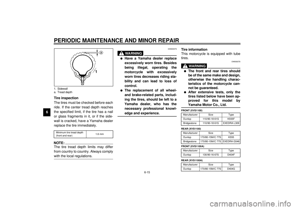
6Tire inspection
The tires must be checked before each
ride. If the center tread depth reaches
the specified limit, if the tire has a nail
or glass fragments in it, or if the side-
wall is cracked, have a Yamaha dealer
replace the tire immediately.
CE-08ENOTE:@ The tire tread depth limits may differ
from country to country. Always comply
with the local regulations. @
EW000079
WARNING
@ l
Have a Yamaha dealer replace
excessively worn tires. Besides
being illegal, operating the
motorcycle with excessively
worn tires decreases riding sta-
bility and can lead to loss of
control.
l
The replacement of all wheel-
and brake-related parts, includ-
ing the tires, should be left to a
Yamaha dealer, who has the
necessary professional knowl-
edge and experience.
@
Tire information
This motorcycle is equipped with tube
tires.
EW000078
WARNING
@ l
The front and rear tires should
be of the same make and design,
otherwise the handling charac-
teristics of the motorcycle can-
not be guaranteed.
l
After extensive tests, only the
tires listed below have been ap-
proved for this model by
Yamaha Motor Co., Ltd.
@CE-10E
CE-10E
1. Sidewall
a. Tread depthMinimum tire tread depth
(front and rear)1.6 mm
FRONT (XVS1100)
Manufacturer Size Type
Dunlop 110/90-18 61S K555F
Bridgestone 110/90-18 61S EXEDRA L309
REAR (XVS1100)
Manufacturer Size Type
Dunlop 170/80-15M/C 77S K555
Bridgestone 170/80-15M/C 77S EXEDRA G546
FRONT (XVS1100A)
Manufacturer Size Type
Dunlop 130/90-16 67S D404F
REAR (XVS1100A)
Manufacturer Size Type
Dunlop 170/80-15M/C 77S D404G
E_5KS.book Page 15 Monday, August 21, 2000 10:48 AM