xvs 1100 a YAMAHA XVS1100A 2000 Owner's Manual
[x] Cancel search | Manufacturer: YAMAHA, Model Year: 2000, Model line: XVS1100A, Model: YAMAHA XVS1100A 2000Pages: 104, PDF Size: 14.79 MB
Page 68 of 104
PERIODIC MAINTENANCE AND MINOR REPAIR
6-19
6
EAU01746*
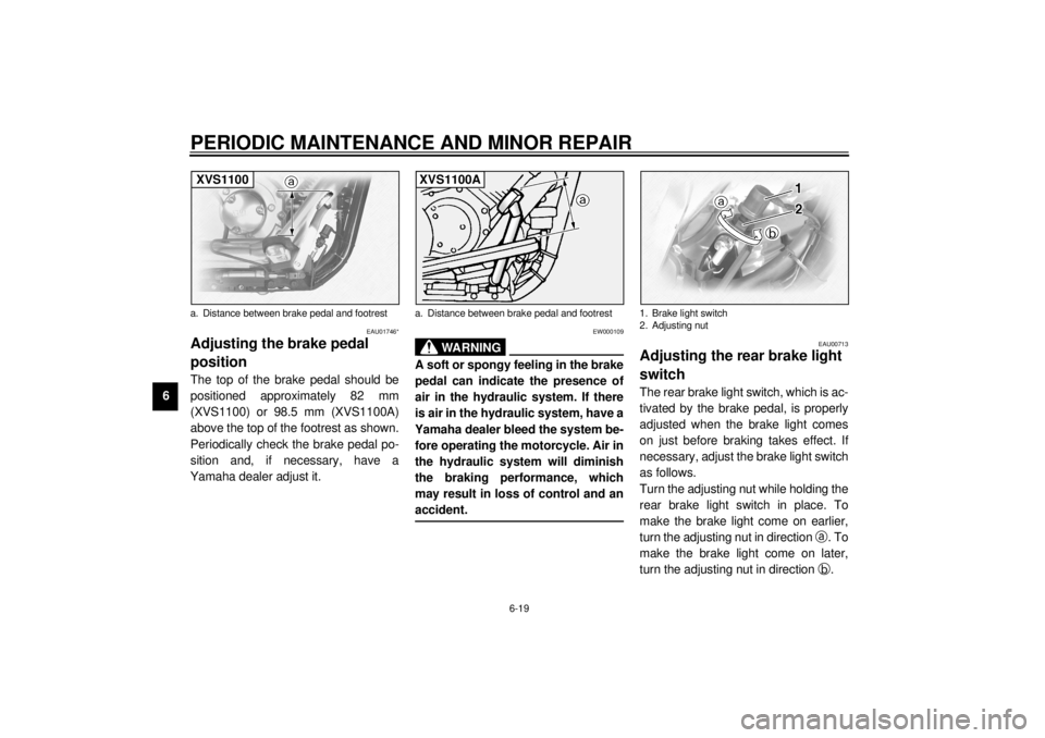
Adjusting the brake pedal
position The top of the brake pedal should be
positioned approximately 82 mm
(XVS1100) or 98.5 mm (XVS1100A)
above the top of the footrest as shown.
Periodically check the brake pedal po-
sition and, if necessary, have a
Yamaha dealer adjust it.
EW000109
WARNING
@ A soft or spongy feeling in the brake
pedal can indicate the presence of
air in the hydraulic system. If there
is air in the hydraulic system, have a
Yamaha dealer bleed the system be-
fore operating the motorcycle. Air in
the hydraulic system will diminish
the braking performance, which
may result in loss of control and an
accident. @
EAU00713
Adjusting the rear brake light
switch The rear brake light switch, which is ac-
tivated by the brake pedal, is properly
adjusted when the brake light comes
on just before braking takes effect. If
necessary, adjust the brake light switch
as follows.
Turn the adjusting nut while holding the
rear brake light switch in place. To
make the brake light come on earlier,
turn the adjusting nut in direction
a. To
make the brake light come on later,
turn the adjusting nut in direction
b.
a. Distance between brake pedal and footrestXVS1100
a. Distance between brake pedal and footrestXVS1100A
1. Brake light switch
2. Adjusting nut
E_5KS.book Page 19 Monday, August 21, 2000 10:48 AM
Page 76 of 104
PERIODIC MAINTENANCE AND MINOR REPAIR
6-27
6To charge the battery
Have a Yamaha dealer charge the bat-
tery as soon as possible if it seems to
have discharged. Keep in mind that the
battery tends to discharge more quickly
if the motorcycle is equipped with op-
tional electrical accessories.
To store the battery
1. If the motorcycle will not be used
for more than one month, remove
the battery, fully charge it, and
then place it in a cool, dry place.2. If the battery will be stored for
more than two months, check it at
least once a month and fully
charge it if necessary.
3. Fully charge the battery before in-
stallation.
4. After installation, make sure that
the battery leads are properly con-
nected to the battery terminals.
EC000102
CAUTION:@ l
Always keep the battery
charged. Storing a discharged
battery can cause permanent
battery damage.
l
To charge a sealed-type (MF)
battery, a special (con-
stant-voltage) battery charger is
required. Using a conventional
battery charger will damage the
battery. If you do not have ac-
cess to a sealed-type (MF) bat-
tery charger, have a Yamaha
dealer charge your battery.
@
EAU01711
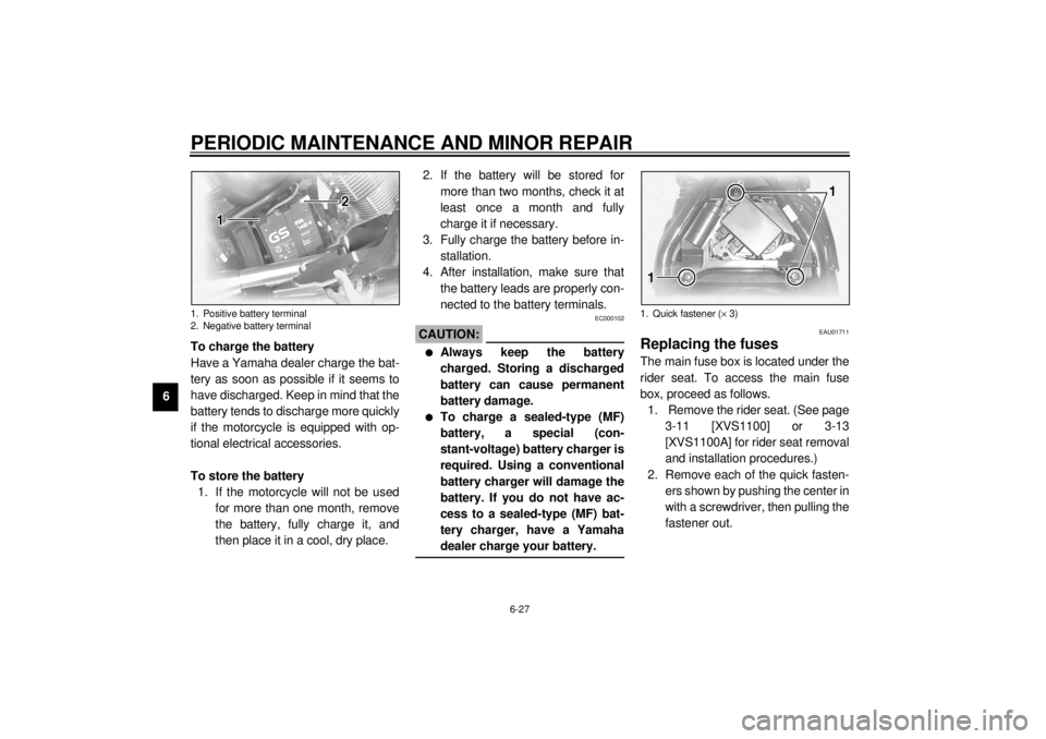
Replacing the fuses The main fuse box is located under the
rider seat. To access the main fuse
box, proceed as follows.
1. Remove the rider seat. (See page
3-11 [XVS1100] or 3-13
[XVS1100A] for rider seat removal
and installation procedures.)
2. Remove each of the quick fasten-
ers shown by pushing the center in
with a screwdriver, then pulling the
fastener out.
1. Positive battery terminal
2. Negative battery terminal
1. Quick fastener (´ 3)
E_5KS.book Page 27 Monday, August 21, 2000 10:48 AM
Page 80 of 104
PERIODIC MAINTENANCE AND MINOR REPAIR
6-31
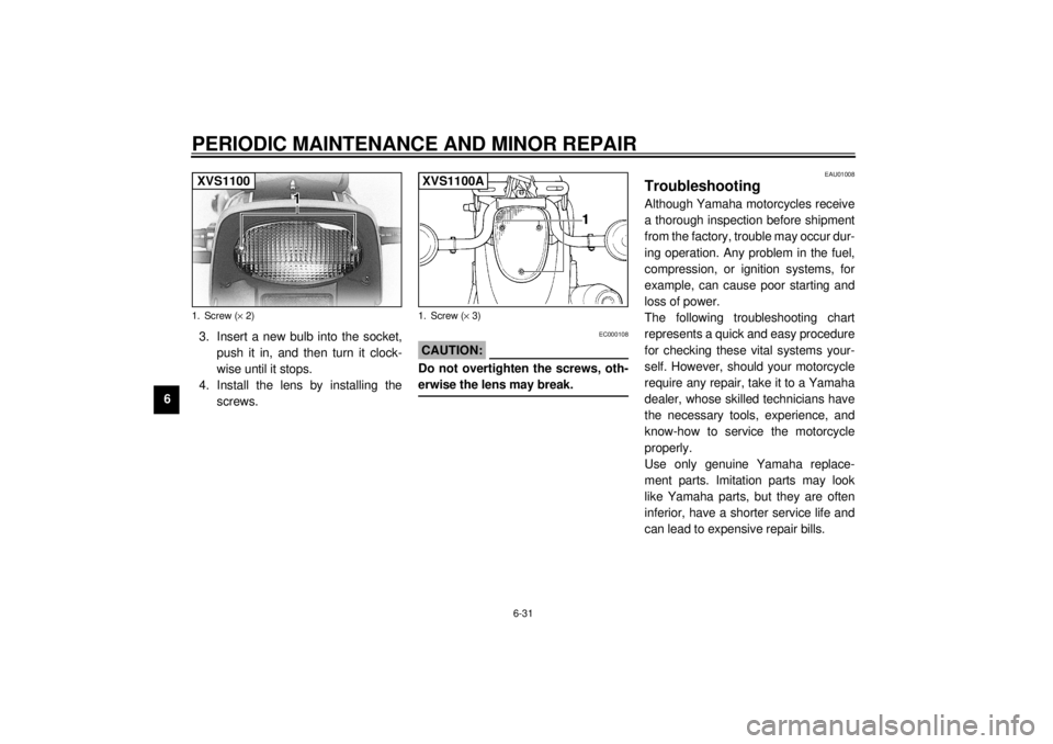
63. Insert a new bulb into the socket,
push it in, and then turn it clock-
wise until it stops.
4. Install the lens by installing the
screws.
EC000108
CAUTION:@ Do not overtighten the screws, oth-
erwise the lens may break. @
EAU01008
Troubleshooting Although Yamaha motorcycles receive
a thorough inspection before shipment
from the factory, trouble may occur dur-
ing operation. Any problem in the fuel,
compression, or ignition systems, for
example, can cause poor starting and
loss of power.
The following troubleshooting chart
represents a quick and easy procedure
for checking these vital systems your-
self. However, should your motorcycle
require any repair, take it to a Yamaha
dealer, whose skilled technicians have
the necessary tools, experience, and
know-how to service the motorcycle
properly.
Use only genuine Yamaha replace-
ment parts. Imitation parts may look
like Yamaha parts, but they are often
inferior, have a shorter service life and
can lead to expensive repair bills.
1. Screw (´ 2)XVS1100
1. Screw (´ 3)XVS1100A
E_5KS.book Page 31 Monday, August 21, 2000 10:48 AM
Page 90 of 104
8-1
8
EAU01038
8-SPECIFICATIONSSpecifications CS-01E
Model XVS1100/XVS1100A
Dimensions
XVS1100
Overall length 2,405 mm
Overall width 895 mm
Overall height 1,095 mm
Seat height 690 mm
Wheelbase 1,640 mm
Ground clearance 145 mm
Minimum turning radius 3,200 mm
XVS1100A
Overall length 2,465 mm
Overall width 945 mm
Overall height 1,095 mm
Seat height 710 mm
Wheelbase 1,645 mm
Ground clearance 145 mm
Minimum turning radius 3,300 mm
Basic weight (with oil and full
fuel tank)
XVS1100274 kg (except for D, A, SF)
275 kg (only for D, A, SF)
XVS1100A288 kgEngine
Engine type Air-cooled 4-stroke, SOHC
Cylinder arrangement V type 2-cylinder
Displacement 1,063 cm
3
Bore ´ stroke 95.0 ´ 75.0 mm
Compression ratio 8.3:1
Star ting system Electric star ter
Lubrication system Wet sump
Engine oil
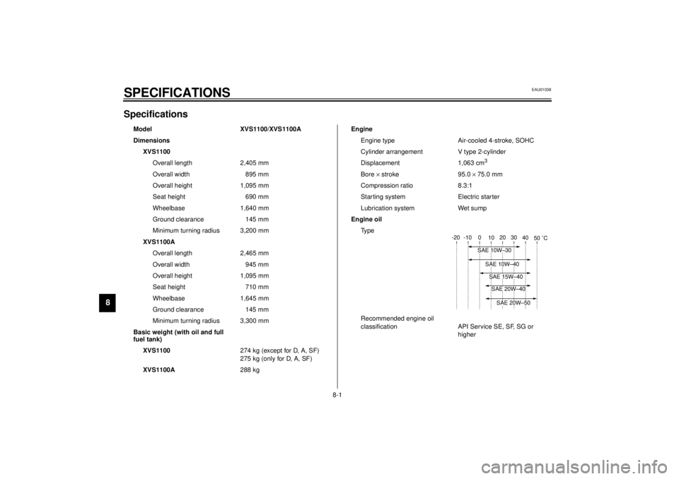
Ty p e
Recommended engine oil
classification API Service SE, SF, SG or
higher
-20 -10 0
10 20 30
40
50 °C
SAE 10W–30
SAE 15W–40SAE 20W–40SAE 20W–50
SAE 10W–40
E_5KS.book Page 1 Monday, August 21, 2000 10:48 AM
Page 91 of 104
SPECIFICATIONS
8-2
8
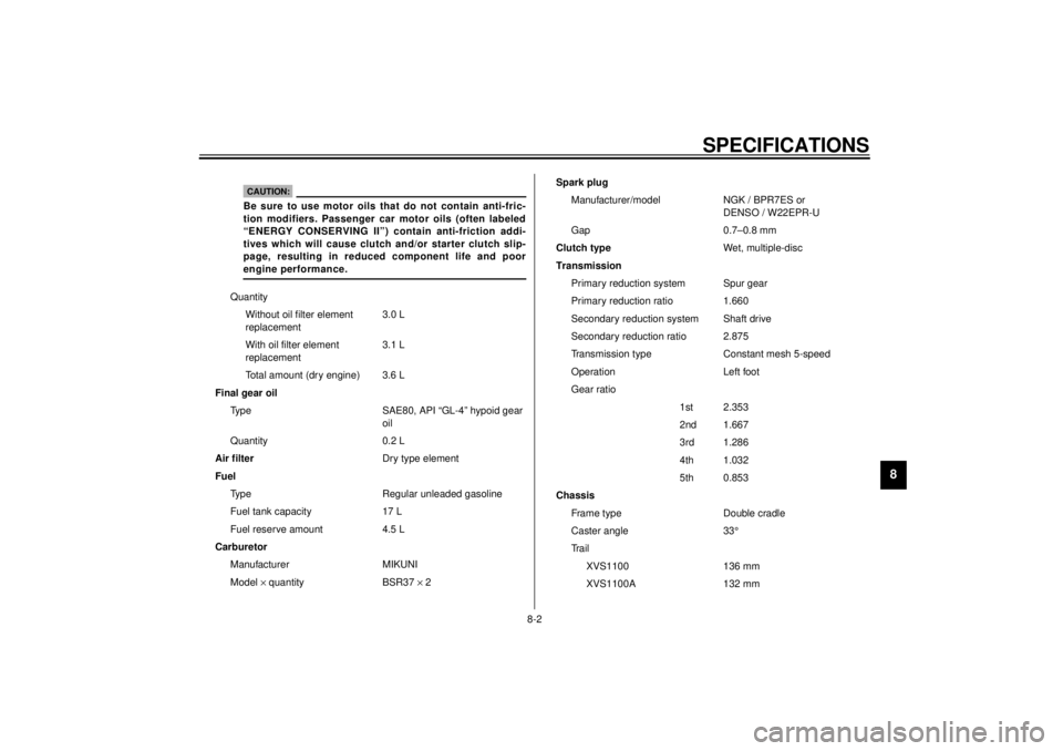
Quantity
Without oil filter element
replacement3.0 L
With oil filter element
replacement3.1 L
Total amount (dry engine) 3.6 L
Final gear oil
Type SAE80, API “GL-4” hypoid gear
oil
Quantity 0.2 L
Air filterDry type element
Fuel
Type Regular unleaded gasoline
Fuel tank capacity 17 L
Fuel reserve amount 4.5 L
Carburetor
Manufacturer MIKUNI
Model ´ quantity BSR37 ´ 2
CAUTION:Be sure to use motor oils that do not contain anti-fric-
tion modifiers. Passenger car motor oils (often labeled
“ENERGY CONSERVING II”) contain anti-friction addi-
tives which will cause clutch and/or starter clutch slip-
page, resulting in reduced component life and poor
engine performance.
Spark plug
Manufacturer/model NGK / BPR7ES or
DENSO / W22EPR-U
Gap 0.7–0.8 mm
Clutch typeWet, multiple-disc
Transmission
Primary reduction system Spur gear
Primary reduction ratio 1.660
Secondary reduction system Shaft drive
Secondary reduction ratio 2.875
Transmission type Constant mesh 5-speed
Operation Left foot
Gear ratio
1st 2.353
2nd 1.667
3rd 1.286
4th 1.032
5th 0.853
Chassis
Frame type Double cradle
Caster angle 33°
Tr a i l
XVS1100 136 mm
XVS1100A 132 mm
E_5KS.book Page 2 Monday, August 21, 2000 10:48 AM
Page 92 of 104

SPECIFICATIONS
8-3
8
Tires
XVS1100
Front
Type Tube
Size 110/90-18 61S
Manufacturer/
model Bridgestone / EXEDRA L309
Dunlop / K555F
Rear
Type Tube
Size 170/80-15 M/C 77S
Manufacturer/
model Bridgestone / EXEDRA G546
Dunlop / K555
Maximum load* 200 kg (only for D, A, SF)
201 kg (except for D, A, SF)
Tire air pressure (measured
on cold tires)
Up to 90 kg*
Front 200 kPa (2.00 kg/cm
2, 2.00 bar)
Rear 225 kPa (2.25 kg/cm2, 2.25 bar)
90 kg–maximum*
Front 225 kPa (2.25 kg/cm2, 2.25 bar)
Rear 250 kPa (2.50 kg/cm2, 2.50 bar)
* Total weight of rider, passenger, cargo and accessoriesXVS1100A
Fr o n t
Ty p e Tu b e
Size 130/90-16 67S
Manufacturer/
model Dunlop / D404F
Rear
Ty p e Tu b e
Size 170/80-15 M/C 77S
Manufacturer/
model Dunlop / D404G
Maximum load* 200 kg
Tire air pressure (measured
on cold tires)
Up to 90 kg*
Front 225 kPa (2.25 kg/cm
2, 2.25 bar)
Rear 225 kPa (2.25 kg/cm2, 2.25 bar)
90 kg–maximum*
Front 225 kPa (2.25 kg/cm2, 2.25 bar)
Rear 250 kPa (2.50 kg/cm2, 2.50 bar)
* Total weight of rider, passenger, cargo and accessories
E_5KS.book Page 3 Monday, August 21, 2000 10:48 AM
Page 93 of 104

SPECIFICATIONS
8-4
8
Wheels
XVS1100
Fron t
Type Spoke
Size 18 ´ 2.15
Rear
Type Spoke
Size 15M/C ´ MT4.50
XVS1100A
Fron t
Type Spoke
Size 16 ´ 3.00
Rear
Type Spoke
Size 15M/C ´ MT4.50
Brakes
Front
Type Dual disc brake
Operation Right hand
Fluid DOT 4
Rear
Type Single disc brake
Operation Right foot
Fluid DOT 4Suspension
Front Telescopic fork
Rear Swingarm (link suspension)
Spring/shock absorber
Front Coil spring / oil damper
Rear Coil spring / gas-oil damper,
spring preload adjustable
Wheel travel
Front 140 mm
Rear 113 mm
Electrical system
Ignition system T.C.I. (digital)
Charging system
Type A.C. magneto
Standard output 14 V, 350 W@ 5,000 r/min
Battery
Model GT14B-4
Voltage, capacity 12 V, 12 Ah
Headlight typeQuartz bulb (halogen)
E_5KS.book Page 4 Monday, August 21, 2000 10:48 AM
Page 99 of 104
![YAMAHA XVS1100A 2000 Owners Manual CONSUMER INFORMATION
9-2
9
EAU01804*
Model label The model label is affixed to the frame
under the rider seat. (See page 3-11
[XVS1100] or 3-13 [XVS1100A] for rid-
er seat removal and installation pro YAMAHA XVS1100A 2000 Owners Manual CONSUMER INFORMATION
9-2
9
EAU01804*
Model label The model label is affixed to the frame
under the rider seat. (See page 3-11
[XVS1100] or 3-13 [XVS1100A] for rid-
er seat removal and installation pro](/img/51/53382/w960_53382-98.png)
CONSUMER INFORMATION
9-2
9
EAU01804*
Model label The model label is affixed to the frame
under the rider seat. (See page 3-11
[XVS1100] or 3-13 [XVS1100A] for rid-
er seat removal and installation proce-
dures.) Record the information on this
label in the space provided. This infor-
mation will be needed when ordering
spare parts from a Yamaha dealer.1. Model label
E_5KS.book Page 2 Monday, August 21, 2000 10:48 AM
Page 100 of 104
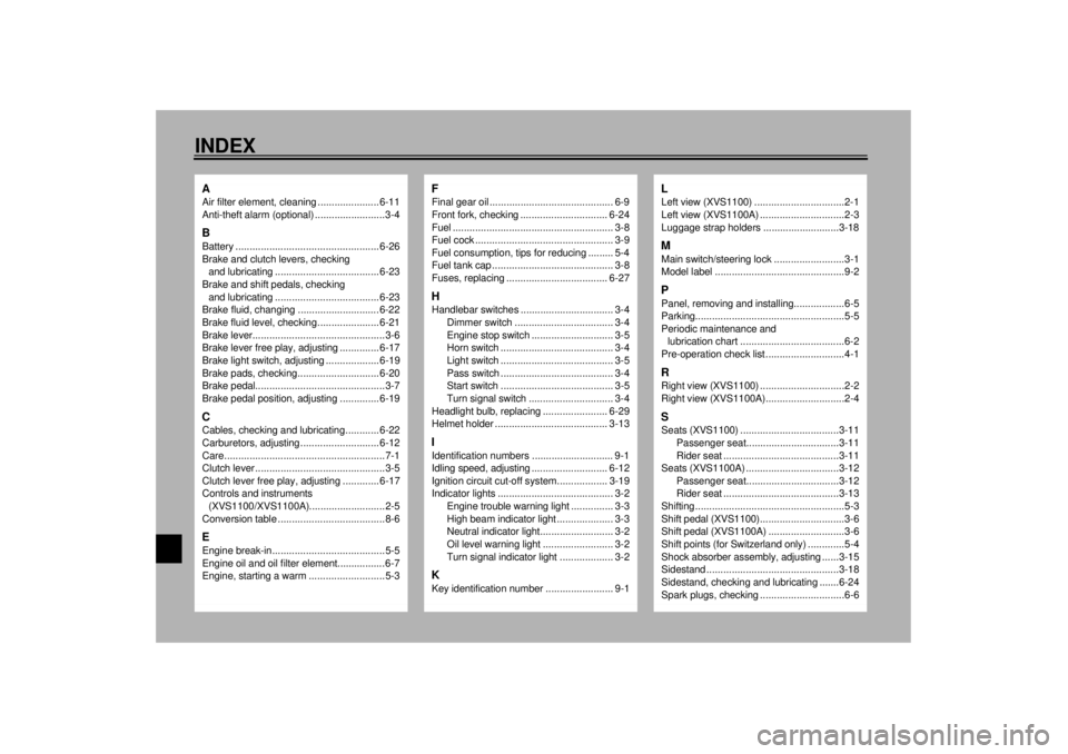
10-INDEXAAir filter element, cleaning ...................... 6-11
Anti-theft alarm (optional) .........................3-4BBattery ................................................... 6-26
Brake and clutch levers, checking
and lubricating ..................................... 6-23
Brake and shift pedals, checking
and lubricating ..................................... 6-23
Brake fluid, changing ............................. 6-22
Brake fluid level, checking...................... 6-21
Brake lever...............................................3-6
Brake lever free play, adjusting .............. 6-17
Brake light switch, adjusting ................... 6-19
Brake pads, checking............................. 6-20
Brake pedal..............................................3-7
Brake pedal position, adjusting .............. 6-19CCables, checking and lubricating............ 6-22
Carburetors, adjusting............................ 6-12
Care.........................................................7-1
Clutch lever ..............................................3-5
Clutch lever free play, adjusting ............. 6-17
Controls and instruments
(XVS1100/XVS1100A)...........................2-5
Conversion table ......................................8-6EEngine break-in........................................5-5
Engine oil and oil filter element.................6-7
Engine, starting a warm ...........................5-3
FFinal gear oil ............................................ 6-9
Front fork, checking ............................... 6-24
Fuel ......................................................... 3-8
Fuel cock ................................................. 3-9
Fuel consumption, tips for reducing ......... 5-4
Fuel tank cap ........................................... 3-8
Fuses, replacing .................................... 6-27HHandlebar switches ................................. 3-4
Dimmer switch ................................... 3-4
Engine stop switch ............................. 3-5
Horn switch ........................................ 3-4
Light switch ........................................ 3-5
Pass switch ........................................ 3-4
Start switch ........................................ 3-5
Turn signal switch .............................. 3-4
Headlight bulb, replacing ....................... 6-29
Helmet holder ........................................ 3-13IIdentification numbers ............................. 9-1
Idling speed, adjusting ........................... 6-12
Ignition circuit cut-off system.................. 3-19
Indicator lights ......................................... 3-2
Engine trouble warning light ............... 3-3
High beam indicator light .................... 3-3
Neutral indicator light.......................... 3-2
Oil level warning light ......................... 3-2
Turn signal indicator light ................... 3-2KKey identification number ........................ 9-1
LLeft view (XVS1100) ................................2-1
Left view (XVS1100A) ..............................2-3
Luggage strap holders ...........................3-18MMain switch/steering lock .........................3-1
Model label ..............................................9-2PPanel, removing and installing..................6-5
Parking.....................................................5-5
Periodic maintenance and
lubrication chart .....................................6-2
Pre-operation check list ............................4-1RRight view (XVS1100) ..............................2-2
Right view (XVS1100A)............................2-4SSeats (XVS1100) ...................................3-11
Passenger seat.................................3-11
Rider seat .........................................3-11
Seats (XVS1100A) .................................3-12
Passenger seat.................................3-12
Rider seat .........................................3-13
Shifting .....................................................5-3
Shift pedal (XVS1100)..............................3-6
Shift pedal (XVS1100A) ...........................3-6
Shift points (for Switzerland only) .............5-4
Shock absorber assembly, adjusting ......3-15
Sidestand ...............................................3-18
Sidestand, checking and lubricating .......6-24
Spark plugs, checking ..............................6-6
E_5KS.book Page 1 Monday, August 21, 2000 10:48 AM
Page 104 of 104

PRINTED ON RECYCLED PAPER
YAMAHA MOTOR CO., LTD.
5KS-28199-E1
XVS1100
XVS1100A
OWNER’S MANUAL
PRINTED IN JAPAN
2000 · 4 - 0.3 ´ 1 CR
(E)