YAMAHA XVS1300A 2014 User Guide
Manufacturer: YAMAHA, Model Year: 2014, Model line: XVS1300A, Model: YAMAHA XVS1300A 2014Pages: 92, PDF Size: 2.05 MB
Page 11 of 92

SAFETY INFORMATION
1-4
1
tents, can create unstable han-
dling or a slow steering re-
sponse.
This vehicle is not desi gne d to
pull a trailer or to be attached to
a si decar.
Genuine Yamaha Accessories
Choosing accessories for your vehicle
is an important decision. Genuine
Yamaha accessories, which are avail- able only from a Yamaha dealer, have
been designed, tested, and approved
by Yamaha for use on your vehicle.
Many companies with no connection
to Yamaha manufacture parts and ac-
cessories or offer other modifications
for Yamaha vehicles. Yamaha is not in
a position to test the products that
these aftermarket companies produce.
Therefore, Yamaha can neither en-
dorse nor recommend the use of ac-
cessories not sold by Yamaha or
modifications not specifically recom-
mended by Yamaha, even if sold and
installed by a Yamaha dealer. Aftermarket Parts, Accessories, an
d
Mo difications
While you may find aftermarket prod-
ucts similar in design and quality to
genuine Yamaha accessories, recog-
nize that some aftermarket accesso-
ries or modifications are not suitable
because of potential safety hazards to
you or others. Installing aftermarket
products or having other modifications
performed to your vehicle that change
any of the vehicle’s design or operation
characteristics can put you and others
at greater risk of serious injury or
death. You are responsible for injuries
related to changes in the vehicle.
Keep the following guidelines in mind,
as well as those provided under “Load-
ing” when mounting accessories. Never install accessories or carry
cargo that would impair the per-
formance of your motorcycle.
Carefully inspect the accessory
before using it to make sure that it
does not in any way reduce
ground clearance or cornering
clearance, limit suspension travel, steering travel or control opera-
tion, or obscure lights or reflec-
tors.
• Accessories fitted to the han- dlebar or the front fork area can
create instability due to improp-
er weight distribution or aerody-
namic changes. If accessories
are added to the handlebar or
front fork area, they must be as
lightweight as possible and
should be kept to a minimum.
• Bulky or large accessories may seriously affect the stability of
the motorcycle due to aerody-
namic effects. Wind may at-
tempt to lift the motorcycle, or
the motorcycle may become
unstable in cross winds. These
accessories may also cause in-
stability when passing or being
passed by large vehicles.
• Certain accessories can dis- place the operator from his or
her normal riding position. This
improper position limits the
freedom of movement of the
U1CSE1E0.book Page 4 Friday, September 13, 2013 9:33 AM
Page 12 of 92

SAFETY INFORMATION
1-5
1operator and may limit control
ability, therefore, such accesso-
ries are not recommended.
Use caution when adding electri-
cal accessories. If electrical ac-
cessories exceed the capacity of
the motorcycle’s electrical sys-
tem, an electric failure could re-
sult, which could cause a
dangerous loss of lights or engine
power.
Aftermarket Tires an d Rims
The tires and rims that came with your
motorcycle were designed to match
the performance capabilities and to
provide the best combination of han-
dling, braking, and comfort. Other
tires, rims, sizes, and combinations
may not be appropriate. Refer to page
6-15 for tire specifications and more in-
formation on replacing your tires.
Transportin g the Motorcycle
Be sure to observe following instruc-
tions before transporting the motorcy-
cle in another vehicle. Remove all loose items from the
motorcycle.
Check that the fuel cock (if
equipped) is in the “OFF” position
and that there are no fuel leaks.
Point the front wheel straight
ahead on the trailer or in the truck
bed, and choke it in a rail to pre-
vent movement.
Shift the transmission in gear (for
models with a manual transmis-
sion).
Secure the motorcycle with tie-
downs or suitable straps that are
attached to solid parts of the mo-
torcycle, such as the frame or up-
per front fork triple clamp (and not,
for example, to rubber-mounted
handlebars or turn signals, or
parts that could break). Choose
the location for the straps carefully
so the straps will not rub against
painted surfaces during transport.
The suspension should be com-
pressed somewhat by the tie-
downs, if possible, so that the mo-
torcycle will not bounce exces-
sively during transport.
U1CSE1E0.book Page 5 Friday, September 13, 2013 9:33 AM
Page 13 of 92
DESCRIPTION
2-1
2
EAU10411
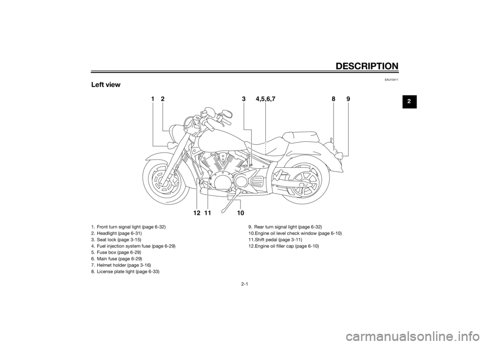
Left view
1238 9
4,5,6,7
10
1112
1. Front turn signal light (page 6-32)
2. Headlight (page 6-31)
3. Seat lock (page 3-15)
4. Fuel injection system fuse (page 6-29)
5. Fuse box (page 6-29)
6. Main fuse (page 6-29)
7. Helmet holder (page 3-16)
8. License plate light (page 6-33) 9. Rear turn signal light (page 6-32)
10.Engine oil level check window (page 6-10)
11.Shift pedal (page 3-11)
12.Engine oil filler cap (page 6-10)
U1CSE1E0.book Page 1 Friday, September 13, 2013 9:33 AM
Page 14 of 92
DESCRIPTION
2-2
2
EAU10421
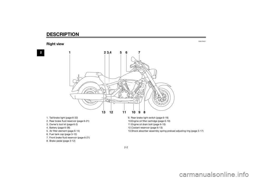
Right view
12
121310 9 8
3,4 5 6 7
11
1. Tail/brake light (page 6-32)
2. Rear brake fluid reservoir (page 6-21)
3. Owner’s tool kit (page 6-2)
4. Battery (page 6-28)
5. Air filter element (page 6-14)
6. Fuel tank cap (page 3-12)
7. Front brake fluid reservoir (page 6-21)
8. Brake pedal (page 3-12) 9. Rear brake light switch (page 6-19)
10.Engine oil filter cartridge (page 6-10)
11.Engine oil drain bolt (page 6-10)
12.Coolant reservoir (page 6-13)
13.Shock absorber assembly spring preload adjusting ring (page 3-17)U1CSE1E0.book Page 2 Friday, September 13, 2013 9:33 AM
Page 15 of 92

DESCRIPTION
2-3
2
EAU10431
Controls and instruments
12 3 4 567
1. Clutch lever (page 3-11)
2. Left handlebar switches (page 3-9)
3. Multi-function meter unit (page 3-6)
4. Main switch/steering lock (page 3-2)
5. Right handlebar switches (page 3-9)
6. Throttle grip (page 6-15)
7. Brake lever (page 3-12)
U1CSE1E0.book Page 3 Friday, September 13, 2013 9:33 AM
Page 16 of 92

INSTRUMENT AND CONTROL FUNCTIONS
3-1
3
EAU10978
Immobilizer systemThis vehicle is equipped with an immo-
bilizer system to help prevent theft by
re-registering codes in the standard
keys. This system consists of the fol-
lowing:
a code re-registering key (with a
red bow)
two standard keys (with a black
bow) that can be re-registered
with new codes
a transponder (which is installed in
the code re-registering key)
an immobilizer unit
an ECU
an immobilizer system indicator
light (See page 3-5.)
The key with the red bow is used to
register codes in each standard key.
Since re-registering is a difficult pro-
cess, take the vehicle along with all
three keys to a Yamaha dealer to have
them re-registered. Do not use the key
with the red bow for driving. It should
only be used for re-registering the
standard keys. Always use a standard
key for driving.
NOTICE
ECA11822
DO NOT LOSE THE CODE RE-
REGISTERING KEY! CONTACT
YOUR DEALER IMMEDIATELY
IF IT IS LOST! If the co de re-re g-
isterin g key is lost, reg istering
new co des in the stan dar d keys
is impossib le. The stan dar d
keys can still be used to start
the vehicle, however if cod e re-
re gisterin g is require d (i.e., if a
new stan dar d key is mad e or all
keys are lost) the entire immo bi-
lizer system must be replaced .
Therefore, it is hi ghly recom- men
ded to use either stan dar d
key an d keep the co de re-reg is-
tering key in a safe place.
Do not su bmerse any key in wa-
ter.
Do not expose any key to exces-
sively hi gh temperatures.
Do not place any key close to
ma gnets (this inclu des, but not
limite d to, pro ducts such as
speakers, etc.).
Do n
ot place items that transmit
electrical si gnals close to any
key.
Do not place heavy items on any
key.
Do not grin d any key or alter its
shape.
Do not d isassemble the plastic
part of any key.
Do not put two keys of any im-
mo bilizer system on the same
key rin g.
Keep the stan dar d keys as well
as keys of other immo bilizer
systems away from this vehi-
cle’s co de re-reg istering key.
1. Code re-registering key (red bow)
2. Standard keys (black bow)U1CSE1E0.book Page 1 Friday, September 13, 2013 9:33 AM
Page 17 of 92
INSTRUMENT AND CONTROL FUNCTIONS
3-2
3
Keep other immo bilizer system
keys away from the main switch
as they may cause si gnal inter-
ference.
EAU10473
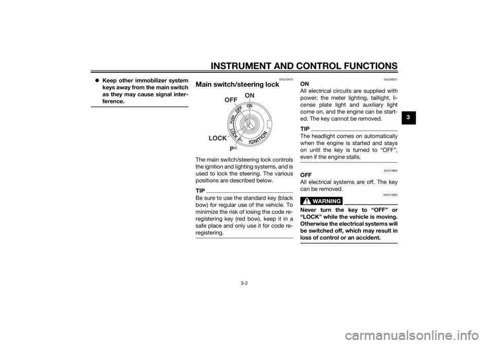
Main switch/steerin g lockThe main switch/steering lock controls
the ignition and lighting systems, and is
used to lock the steering. The various
positions are described below.TIPBe sure to use the standard key (black
bow) for regular use of the vehicle. To
minimize the risk of losing the code re-
registering key (red bow), keep it in a
safe place and only use it for code re-
registering.
EAU38531
ON
All electrical circuits are supplied with
power; the meter lighting, taillight, li-
cense plate light and auxiliary light
come on, and the engine can be start-
ed. The key cannot be removed.TIPThe headlight comes on automatically
when the engine is started and stays
on until the key is turned to “OFF”,
even if the engine stalls.
EAU10662
OFF
All electrical systems are off. The key
can be removed.
WARNING
EWA10062
Never turn the key to “OFF” or
“LOCK” while the vehicle is movin g.
Otherwise the electrical systems will
b e switche d off, which may result in
loss of control or an acci dent.
P
ON
OFF
LOCK
U1CSE1E0.book Page 2 Friday, September 13, 2013 9:33 AM
Page 18 of 92

INSTRUMENT AND CONTROL FUNCTIONS
3-3
3
EAU10685
LOCK
The steering is locked, and all electrical
systems are off. The key can be re-
moved.
To lock the steering1. Turn the handlebars all the way tothe left.
2. Push the key in from the “OFF” position, and then turn it to
“LOCK” while still pushing it.
3. Remove the key. To unlock the steering
Push the key in, and then turn it to
“OFF” while still pushing it.
EAU34342
(Parkin
g)
The steering is locked, and the taillight,
license plate light and auxiliary light are
on. The hazard lights and turn signal
lights can be turned on, but all other
electrical systems are off. The key can
be removed.
The steering must be locked before the
key can be turned to “ ”.
NOTICE
ECA11021
Do not use the parkin g position for
an exten ded len gth of time, other-
wise the battery may d ischarge.
1. Push.
2. Turn.12
1. Push.
2. Turn.12
U1CSE1E0.book Page 3 Friday, September 13, 2013 9:33 AM
Page 19 of 92
INSTRUMENT AND CONTROL FUNCTIONS
3-4
3
EAU49394
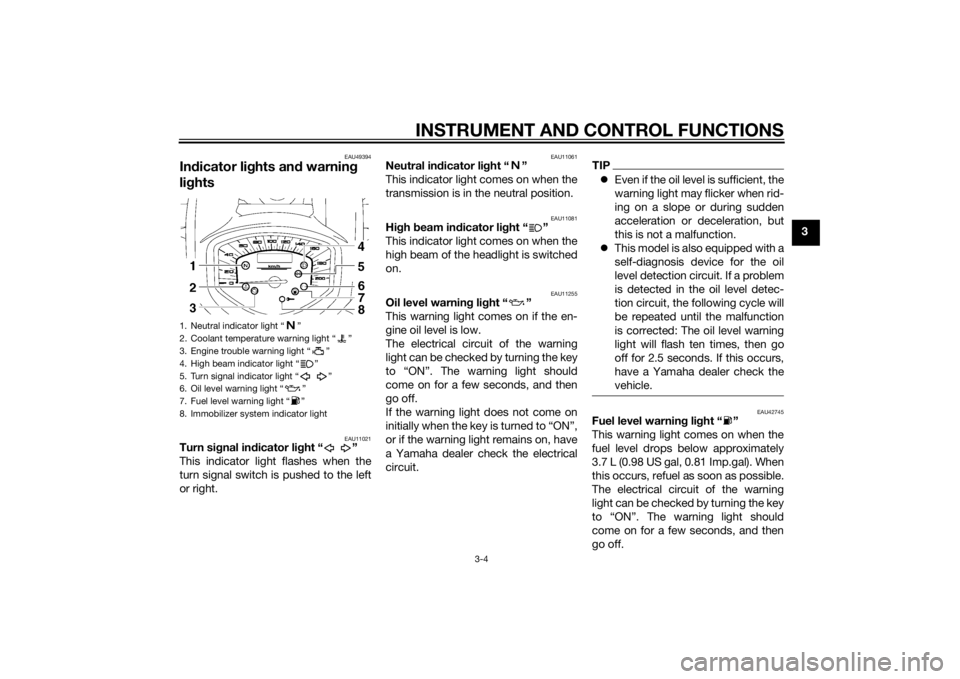
Indicator lig hts and warning
lig hts
EAU11021
Turn si gnal in dicator li ght “ ”
This indicator light flashes when the
turn signal switch is pushed to the left
or right.
EAU11061
Neutral in dicator li ght “ ”
This indicator light comes on when the
transmission is in the neutral position.
EAU11081
Hi gh beam in dicator li ght “ ”
This indicator light comes on when the
high beam of the headlight is switched
on.
EAU11255
Oil level warnin g lig ht “ ”
This warning light comes on if the en-
gine oil level is low.
The electrical circuit of the warning
light can be checked by turning the key
to “ON”. The warning light should
come on for a few seconds, and then
go off.
If the warning light does not come on
initially when the key is turned to “ON”,
or if the warning light remains on, have
a Yamaha dealer check the electrical
circuit.
TIP Even if the oil level is sufficient, the
warning light may flicker when rid-
ing on a slope or during sudden
acceleration or deceleration, but
this is not a malfunction.
This model is also equipped with a
self-diagnosis device for the oil
level detection circuit. If a problem
is detected in the oil level detec-
tion circuit, the following cycle will
be repeated until the malfunction
is corrected: The oil level warning
light will flash ten times, then go
off for 2.5 seconds. If this occurs,
have a Yamaha dealer check the
vehicle.
EAU42745
Fuel level warnin g li ght “ ”
This warning light comes on when the
fuel level drops below approximately
3.7 L (0.98 US gal, 0.81 Imp.gal). When
this occurs, refuel as soon as possible.
The electrical circuit of the warning
light can be checked by turning the key
to “ON”. The warning light should
come on for a few seconds, and then
go off.
1. Neutral indicator light “ ”
2. Coolant temperature warning light “ ”
3. Engine trouble warning light “ ”
4. High beam indicator light “ ”
5. Turn signal indicator light “ ”
6. Oil level warning light “ ”
7. Fuel level warning light “ ”
8. Immobilizer system indicator light
U1CSE1E0.book Page 4 Friday, September 13, 2013 9:33 AM
Page 20 of 92
INSTRUMENT AND CONTROL FUNCTIONS
3-5
3If the warning light does not come on
initially when the key is turned to “ON”,
or if the warning light remains on, have
a Yamaha dealer check the electrical
circuit.
TIP
The vehicle must be on a level sur-
face and positioned upright, oth-
erwise the fuel level warning light
may not come on and go off at the
appropriate times.
This model is also equipped with a
self-diagnosis device for the fuel
level detection circuit. If a problem
is detected in the fuel level detec-
tion circuit, the following cycle will
be repeated until the malfunction
is corrected: The fuel level warning
light will flash eight times, and
then go off for 3.0 seconds. If this
occurs, have a Yamaha dealer
check the vehicle.
EAU11447
Coolant temperature warnin g
li g ht “ ”
This warning light comes on if the en-
gine overheats. If this occurs, stop the
engine immediately and allow the en-
gine to cool.
The electrical circuit of the warning
light can be checked by turning the key
to “ON”. The warning light should
come on for a few seconds, and then
go off.
If the warning light does not come on
initially when the key is turned to “ON”,
or if the warning light remains on, have
a Yamaha dealer check the electrical
circuit.NOTICE
ECA10022
Do not continue to operate the en-
g ine if it is overheatin g.TIP For radiator-fan-equipped vehi-
cles, the radiator fan(s) automati-
cally switch on or off according to
the coolant temperature in the ra-
diator.
If the engine overheats, see page
6-38 for further instructions.
EAU42775
Engine trou ble warnin g lig ht “ ”
This warning light comes on if a prob-
lem is detected in the electrical circuit
monitoring the engine. If this occurs,
have a Yamaha dealer check the self-
diagnosis system. (See page 3-8 for an
explanation of the self-diagnosis de-
vice.)
The electrical circuit of the warning
light can be checked by turning the key
to “ON”. The warning light should
come on for a few seconds, and then
go off.
If the warning light does not come on
initially when the key is turned to “ON”,
or if the warning light remains on, have
a Yamaha dealer check the electrical
circuit.
EAU38625
Immo bilizer system in dicator li ght
The electrical circuit of the indicator
light can be checked by turning the key
to “ON”. The indicator light should
come on for a few seconds, and then
go off.
U1CSE1E0.book Page 5 Friday, September 13, 2013 9:33 AM