YAMAHA XVS1300A 2014 Owner's Guide
Manufacturer: YAMAHA, Model Year: 2014, Model line: XVS1300A, Model: YAMAHA XVS1300A 2014Pages: 92, PDF Size: 2.05 MB
Page 31 of 92
INSTRUMENT AND CONTROL FUNCTIONS
3-16
3
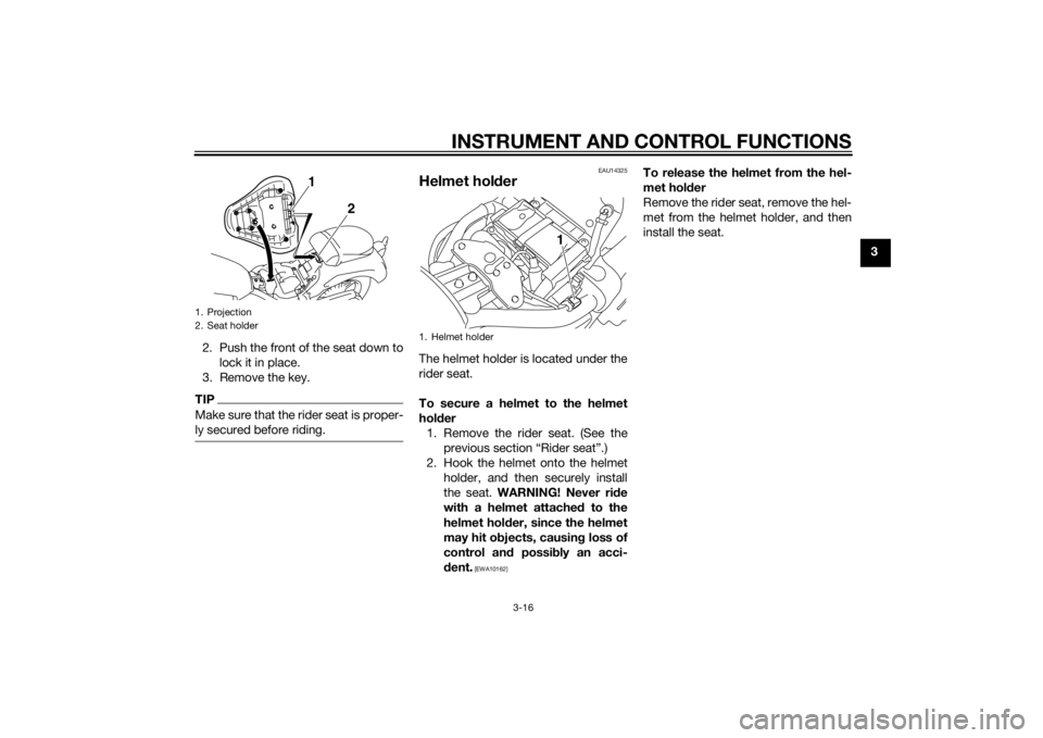
2. Push the front of the seat down to lock it in place.
3. Remove the key.
TIPMake sure that the rider seat is proper-
ly secured before riding.
EAU14325
Helmet hol derThe helmet holder is located under the
rider seat.
To secure a helmet to the helmet
hol der
1. Remove the rider seat. (See the previous section “Rider seat”.)
2. Hook the helmet onto the helmet holder, and then securely install
the seat. WARNING! Never ri de
with a helmet attached to the
helmet hol der, since the helmet
may hit o bjects, causin g loss of
control an d possi bly an acci-
d ent.
[EWA10162]
To release the helmet from the hel-
met hol der
Remove the rider seat, remove the hel-
met from the helmet holder, and then
install the seat.
1. Projection
2. Seat holder
1
2
1. Helmet holder
1
U1CSE1E0.book Page 16 Friday, September 13, 2013 9:33 AM
Page 32 of 92
INSTRUMENT AND CONTROL FUNCTIONS
3-17
3
EAU42547
Adjustin g the shock a bsorb er
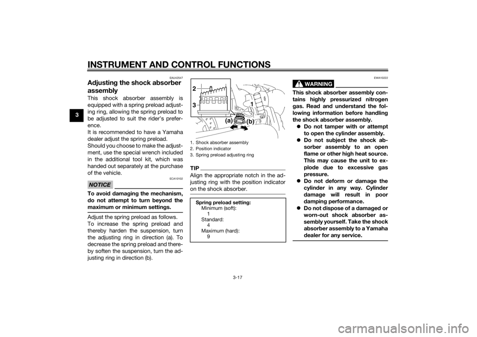
assem blyThis shock absorber assembly is
equipped with a spring preload adjust-
ing ring, allowing the spring preload to
be adjusted to suit the rider’s prefer-
ence.
It is recommended to have a Yamaha
dealer adjust the spring preload.
Should you choose to make the adjust-
ment, use the special wrench included
in the additional tool kit, which was
handed out separately at the purchase
of the vehicle.NOTICE
ECA10102
To avoi d d amag ing the mechanism,
d o not attempt to turn b eyond the
maximum or minimum setting s.Adjust the spring preload as follows.
To increase the spring preload and
thereby harden the suspension, turn
the adjusting ring in direction (a). To
decrease the spring preload and there-
by soften the suspension, turn the ad-
justing ring in direction (b).
TIPAlign the appropriate notch in the ad-
justing ring with the position indicator
on the shock absorber.
WARNING
EWA10222
This shock absor ber assem bly con-
tains hi ghly pressurize d nitro gen
g as. Rea d an d und erstan d the fol-
lowin g information b efore handlin g
the shock a bsor ber assem bly.
Do not tamper with or attempt
to open the cylin der assem bly.
Do not su bject the shock a b-
sor ber assem bly to an open
flame or other hi gh heat source.
This may cause the unit to ex-
plo de due to excessive gas
pressure.
Do not deform or d amage the
cylin der in any way. Cylin der
d amag e will result in poor
d ampin g performance.
Do not d ispose of a damag ed or
worn-out shock a bsor ber as-
sem bl
y yourself. Take the shock
a b sor ber assem bly to a Yamaha
d ealer for any service.
1. Shock absorber assembly
2. Position indicator
3. Spring preload adjusting ringSprin g preloa d setting :
Minimum (soft): 1
Standard: 4
Maximum (hard):
923
U1CSE1E0.book Page 17 Friday, September 13, 2013 9:33 AM
Page 33 of 92

INSTRUMENT AND CONTROL FUNCTIONS
3-18
3
EAU15306
Sidestan dThe sidestand is located on the left
side of the frame. Raise the sidestand
or lower it with your foot while holding
the vehicle upright.TIPThe built-in sidestand switch is part of
the ignition circuit cut-off system,
which cuts the ignition in certain situa-
tions. (See the following section for an
explanation of the ignition circuit cut-
off system.)
WARNING
EWA10242
The vehicle must not b e ridden with
the si destan d d own, or if the si de-
stan d cannot b e properly move d up
(or does not stay up), otherwise the
si destan d coul d contact the groun d
an d d istract the operator, resultin g
in a possi ble loss of control.
Yamaha’s i gnition circuit cut-off
system has been desi gne d to assist
the operator in fulfilling the respon-
si bility of raisin g the si destan d b e-
fore startin g off. Therefore, check this system re
gularly an d have a
Yamaha dealer repair it if it does not
function properly.
EAU44893
I g nition circuit cut-off systemThe ignition circuit cut-off system
(comprising the sidestand switch,
clutch switch and neutral switch) has
the following functions.
It prevents starting when the
transmission is in gear and the
sidestand is up, but the clutch le-
ver is not pulled.
It prevents starting when the
transmission is in gear and the
clutch lever is pulled, but the side-
stand is still down.
It cuts the running engine when
the transmission is in gear and the
sidestand is moved down.
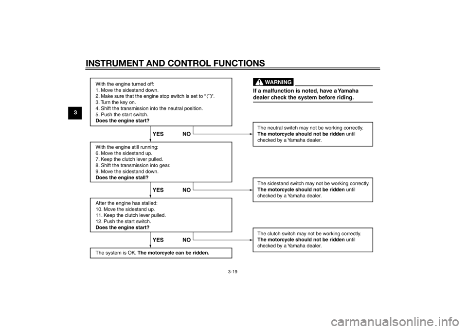
Periodically check the operation of the
ignition circuit cut-off system accord-
ing to the following procedure.
U1CSE1E0.book Page 18 Friday, September 13, 2013 9:33 AM
Page 34 of 92
INSTRUMENT AND CONTROL FUNCTIONS
3-19
3
With the engine turned off:
1. Move the sidestand down.
2. Make sure that the engine stop switch is set to “
3. Turn the key on.
4. Shift the transmission into the neutral position.
5. Push the start switch.
Does the engine start?
With the engine still running:
6. Move the sidestand up.
7. Keep the clutch lever pulled.
8. Shift the transmission into gear.
9. Move the sidestand down.
Does the engine stall?
After the engine has stalled:
10. Move the sidestand up.
11. Keep the clutch lever pulled.
12. Push the start switch.
Does the engine start?
The system is OK. The motorcycle can be ridden. The neutral switch may not be working correctly.
The motorcycle should not be ridden
until
checked by a Yamaha dealer.
The sidestand switch may not be working correctly.
The motorcycle should not be ridden until
checked by a Yamaha dealer.
The clutch switch may not be working correctly.
The motorcycle should not be ridden until
checked by a Yamaha dealer.
YES NO YES NO YES NO
If a malfunction is noted, have a Yamaha
dealer check the system before riding.
WARNING
”.
U1CSE1E0.book Page 19 Friday, September 13, 2013 9:33 AM
Page 35 of 92
FOR YOUR SAFETY – PRE-OPERATION CHECKS
4-1
4
EAU15598
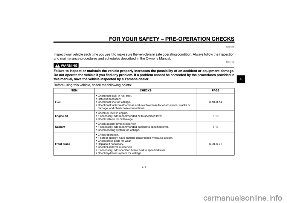
Inspect your vehicle each time you use it to make sure the vehicle is in safe operating condition. Always follow the inspection
and maintenance procedures and schedules described in the Owner’s Manual.
WARNING
EWA11152
Failure to inspect or maintain the vehicle properly increases the possibility of an acci dent or equipment damag e.
Do not operate the vehicle if you fin d any pro blem. If a pro blem cannot be corrected b y the proce dures provi ded in
this manual, have the vehicle inspecte d b y a Yamaha dealer.Before using this vehicle, check the following points:
ITEM CHECKS PAGE
Fuel • Check fuel level in fuel tank.
• Refuel if necessary.
• Check fuel line for leakage.
• Check fuel tank breather hose and overflow hose for obstructions, cracks or
damage, and check hose connections. 3-13, 3-14
En gine oil • Check oil level in engine.
• If necessary, add recommended oil to specified level.
• Check vehicle for oil leakage. 6-10
Coolant • Check coolant level in reservoir.
• If necessary, add recommended coolant to specified level.
• Check cooling system for leakage. 6-13
Front brake • Check operation.
• If soft or spongy, have Yamaha dealer bleed hydraulic system.
• Check brake pads for wear.
• Replace if necessary.
• Check fluid level in reservoir.
• If necessary, add specified brake fluid to specified level.
• Check hydraulic system for leakage. 6-20, 6-21
U1CSE1E0.book Page 1 Friday, September 13, 2013 9:33 AM
Page 36 of 92

FOR YOUR SAFETY – PRE-OPERATION CHECKS
4-2
4
Rear brake • Check operation.
• If soft or spongy, have Yamaha dealer bleed hydraulic system.
• Check brake pads for wear.
• Replace if necessary.
• Check fluid level in reservoir.
• If necessary, add specified brake fluid to specified level.
• Check hydraulic system for leakage. 6-20, 6-21
Clutch • Check operation.
• Lubricate cable if necessary.
• Check lever free play.
• Adjust if necessary.
6-18
Throttle g rip • Make sure that operation is smooth.
• Check throttle grip free play.
• If necessary, have Yamaha dealer adjust throttle grip free play and lubricate ca-
ble and grip housing. 6-15, 6-24
Control ca bles • Make sure that operation is smooth.
• Lubricate if necessary. 6-23
Wheels an d tires •Check for damage.
• Check tire condition and tread depth.
• Check air pressure.
• Correct if necessary.
6-15, 6-17
Brake an d shift pe dals • Make sure that operation is smooth.
• Lubricate pedal pivoting points if necessary.
6-24
Brake an d clutch levers • Make sure that operation is smooth.
• Lubricate lever pivoting points if necessary. 6-25
Si destan d • Make sure that operation is smooth.
• Lubricate pivot if necessary.
6-25
Chassis fasteners • Make sure that all nuts, bolts and screws are properly tightened.
• Tighten if necessary.
—
Instruments, li ghts, si gnals
an d switches • Check operation.
• Correct if necessary.
—
ITEM
CHECKS PAGE
U1CSE1E0.book Page 2 Friday, September 13, 2013 9:33 AM
Page 37 of 92

FOR YOUR SAFETY – PRE-OPERATION CHECKS
4-3
4
Sidestan d switch • Check operation of ignition circuit cut-off system.
• If system is not working correctly, have Yamaha dealer check vehicle. 3-18
ITEM CHECKS PAGE
U1CSE1E0.book Page 3 Friday, September 13, 2013 9:33 AM
Page 38 of 92

OPERATION AND IMPORTANT RIDING POINTS
5-1
5
EAU15952
Read the Owner’s Manual carefully to
become familiar with all controls. If
there is a control or function you do not
understand, ask your Yamaha dealer.
WARNING
EWA10272
Failure to familiarize yourself with
the controls can lead to loss of con-
trol, which coul d cause an acci dent
or injury.
EAU47151
TIPThis model is equipped with: a lean angle sensor to stop the en-
gine in case of a turnover. In this
case, the multi-function meter unit
indicates error code 30, but this is
not a malfunction. Turn the key to
“OFF” and then to “ON” to clear
the error code. Failing to do so will
prevent the engine from starting
even though the engine will crank
when pushing the start switch.
an engine auto-stop system. The
engine stops automatically if left
idling for 20 minutes. In this case,
the multi-function meter unit indi-
cates error code 70, but this is not
a malfunction. Push the start
switch to clear the error code and
to restart the engine.
EAU42888
Startin g the en gineIn order for the ignition circuit cut-off
system to enable starting, one of the
following conditions must be met:
The transmission is in the neutral
position.
The transmission is in gear with
the clutch lever pulled and the
sidestand up.
See page 3-18 for more informa-
tion.
1. Turn the key to “ON” and make sure that the engine stop switch is
set to “ ”.
The following warning lights and
indicator light should come on for
a few seconds, then go off. Oil level warning light
Fuel level warning light
Coolant temperature warning
light
Engine trouble warning light
Immobilizer system indicator
light
U1CSE1E0.book Page 1 Friday, September 13, 2013 9:33 AM
Page 39 of 92
OPERATION AND IMPORTANT RIDING POINTS
5-2
5
NOTICE
ECA11834
If a warning or in dicator li ght does
not come on initially when the key is
turne d to “ON”, or if a warnin g or in-
d icator li ght remains on, see pa ge
3-4 for the correspon din g warnin g
an d in dicator li ght circuit check.2. Shift the transmission into the
neutral position. The neutral indi-
cator light should come on. If not,
ask a Yamaha dealer to check the
electrical circuit.
3. Start the engine by pushing the start switch.
If the engine fails to start, release
the start switch, wait a few sec-
onds, and then try again. Each
starting attempt should be as
short as possible to preserve the
battery. Do not crank the engine
more than 10 seconds on any one
attempt.NOTICE
ECA11043
For maximum en gine life, never ac-
celerate har d when the en gine is
col d!
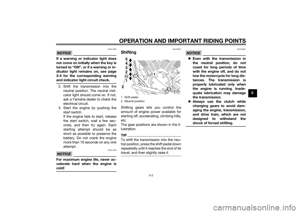
EAU16672
Shiftin gShifting gears lets you control the
amount of engine power available for
starting off, accelerating, climbing hills,
etc.
The gear positions are shown in the il-
lustration.TIPTo shift the transmission into the neu-
tral position, press the shift pedal down
repeatedly until it reaches the end of its
travel, and then slightly raise it.
NOTICE
ECA10261
Even with the transmission in
the neutral position, d o not
coast for lon g period s of time
with the en gine off, an d d o not
tow the motorcycle for lon g d is-
tances. The transmission is
properly lu bricated only when
the en gine is runnin g. Ina de-
quate lu brication may d amage
the transmission.
Always use the clutch while
chan gin g g ears to avoi d d am-
a g in g the en gine, transmission,
an d d rive train, which are not
d esi gne d to withstan d the
shock of force d shiftin g.
1. Shift pedal
2. Neutral position
1
5432N1 5
4
3
2N1
2
U1CSE1E0.book Page 2 Friday, September 13, 2013 9:33 AM
Page 40 of 92

OPERATION AND IMPORTANT RIDING POINTS
5-3
5
EAU16811
Tips for reducin g fuel con-
sumptionFuel consumption depends largely on
your riding style. Consider the follow-
ing tips to reduce fuel consumption:
Shift up swiftly, and avoid high en-
gine speeds during acceleration.
Do not rev the engine while shift-
ing down, and avoid high engine
speeds with no load on the en-
gine.
Turn the engine off instead of let-
ting it idle for an extended length
of time (e.g., in traffic jams, at traf-
fic lights or at railroad crossings).
EAU16842
Engine break-inThere is never a more important period
in the life of your engine than the period
between 0 and 1600 km (1000 mi). For
this reason, you should read the fol-
lowing material carefully.
Since the engine is brand new, do not
put an excessive load on it for the first
1600 km (1000 mi). The various parts in
the engine wear and polish themselves
to the correct operating clearances.
During this period, prolonged full-throt-
tle operation or any condition that
might result in engine overheating
must be avoided.
EAU17024
0–1000 km (0–600 mi)
Avoid prolonged operation above 1/3
throttle. NOTICE: After 1000 km (600
mi) of operation, the en gine oil must
b e chan ged , an d the oil filter car-
tri dg e or element replace d.
[ECA11283]
1000–1600 km (600–1000 mi)
Avoid prolonged operation above 1/2
throttle. 1600 km (1000 mi) an
d b eyon d
The vehicle can now be operated nor-
mally.
NOTICE
ECA10271
If any en gine trou ble shoul d occur
d urin g the en gine break-in perio d,
imme diately have a Yamaha dealer
check the vehicle.
U1CSE1E0.book Page 3 Friday, September 13, 2013 9:33 AM