YAMAHA XVS950CU 2017 Repair Manual
Manufacturer: YAMAHA, Model Year: 2017, Model line: XVS950CU, Model: YAMAHA XVS950CU 2017Pages: 88, PDF Size: 2.38 MB
Page 61 of 88
Periodic maintenance an d a djustment
6-20
6
EAU22393
Checkin g the front an d rear
b rake pa dsThe front and rear brake pads must be
checked for wear at the intervals spec-
ified in the periodic maintenance and
lubrication chart.
EAU22432
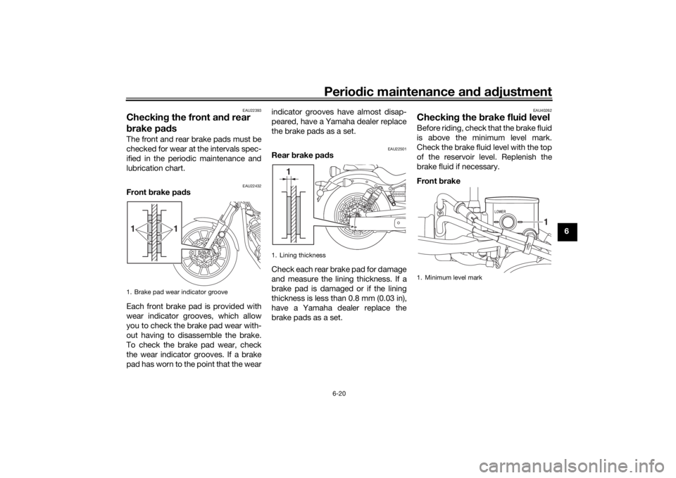
Front brake pad s
Each front brake pad is provided with
wear indicator grooves, which allow
you to check the brake pad wear with-
out having to disassemble the brake.
To check the brake pad wear, check
the wear indicator grooves. If a brake
pad has worn to the point that the wear indicator grooves have almost disap-
peared, have a Yamaha dealer replace
the brake pads as a set.
EAU22501
Rear
brake pa ds
Check each rear brake pad for damage
and measure the lining thickness. If a
brake pad is damaged or if the lining
thickness is less than 0.8 mm (0.03 in),
have a Yamaha dealer replace the
brake pads as a set.
EAU40262
Checkin g the brake flui d levelBefore riding, check that the brake fluid
is above the minimum level mark.
Check the brake fluid level with the top
of the reservoir level. Replenish the
brake fluid if necessary.
Front brake
1. Brake pad wear indicator groove11
1. Lining thickness
1
1. Minimum level mark
1
UBS5E0E0.book Page 20 Wedne sday, October 19, 2016 10:21 AM
Page 62 of 88
Periodic maintenance an d a djustment
6-21
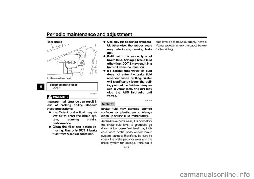
6 Rear
brake
WARNING
EWA16011
Improper maintenance can result in
loss of brakin g a bility. O bserve
these precautions: Insufficient brake flui d may al-
low air to enter the b rake sys-
tem, re ducin g brakin g
performance.
Clean the filler cap before re-
moving . Use only DOT 4 b rake
flui d from a seale d container.
Use only the specified b rake flu-
i d ; otherwise, the ru bber seals
may deteriorate, causin g leak-
a g e.
Refill with the same type of
brake flui d. A ddin g a brake flui d
other than DOT 4 may result in a
harmful chemical reaction.
Be careful that water or dust
d oes not enter the brake flui d
reservoir when refillin g. Water
will si gnificantly lower the boil-
in g point of the flui d an d may re-
sult in vapor lock, an d d ir
t may
clo g the ABS hy draulic unit
valves.
NOTICE
ECA17641
Brake flui d may damag e painted
surfaces or plastic parts. Always
clean up spille d flui d imme diately.As the brake pads wear, it is normal for
the brake fluid level to gradually go
down. A low brake fluid level may indi-
cate worn brake pads and/or brake
system leakage; therefore, be sure to
check the brake pads for wear and the
brake system for leakage. If the brake fluid level goes down suddenly, have a
Yamaha dealer check the cause before further riding.
1. Minimum level markSpecifie d b rake flui d:
DOT 4
1
UBS5E0E0.book Page 21 Wedne sday, October 19, 2016 10:21 AM
Page 63 of 88
Periodic maintenance an d a djustment
6-22
6
EAU22733
Chan gin g the brake flui dHave a Yamaha dealer change the
brake fluid at the intervals specified in
the periodic maintenance and lubrica-
tion chart. In addition, have the oil seals
of the master cylinders and calipers as
well as the brake hoses replaced at the
intervals listed below or whenever they
are damaged or leaking.
Oil seals: Replace every two
years.
Brake hoses: Replace every four
years.
EAU23041
Drive belt slackThe drive belt slack should be checked
and adjusted at the intervals specified
in the periodic maintenance and lubri-
cation chart.
EAU55773
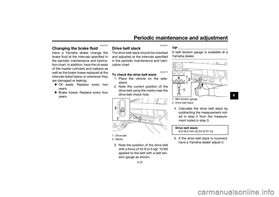
To check the drive belt slack
1. Place the vehicle on the side- stand.
2. Note the current position of the drive belt using the marks near the
drive belt check hole.
3. Note the position of the drive belt with a force of 45 N (4.5 kgf, 10 lbf)
applied to the belt with a belt ten-
sion gauge as shown.
TIPA belt tension gauge is available at a
Yamaha dealer.4. Calculate the drive belt slack bysubtracting the measurement not-
ed in step 2 from the measure-
ment noted in step 3.
5. If the drive belt slack is incorrect, have a Yamaha dealer adjust it.
1. Drive belt
2. Marks2
1
1. Belt tension gauge
2. Drive belt slack
Drive belt slack:
6.0–8.0 mm (0.24–0.31 in)
6 8 10 12 14
1
2
UBS5E0E0.book Page 22 Wedne sday, October 19, 2016 10:21 AM
Page 64 of 88

Periodic maintenance an d a djustment
6-23
6
EAU23098
Checkin g an d lu bricatin g the
ca blesThe operation of all control cables and
the condition of the cables should be
checked before each ride, and the ca-
bles and cable ends should be lubri-
cated if necessary. If a cable is
damaged or does not move smoothly,
have a Yamaha dealer check or re-
place it. WARNING! Dama ge to the
outer housin g of cab les may result
in internal rustin g an d cause inter-
ference with cab le movement. Re-
place damag ed cab les as soon as
possi ble to prevent unsafe con di-
tions.
[EWA10712] EAU49921
Checkin
g an d lu bricatin g the
throttle grip an d cab leThe operation of the throttle grip
should be checked before each ride. In
addition, the cable should be lubricat-
ed by a Yamaha dealer at the intervals
specified in the periodic maintenance
chart.
EAU44276
Checkin g an d lu bricatin g the
b rake an d shift pe dalsThe operation of the brake and shift
pedals should be checked before each
ride, and the pedal pivots should be lu-
bricated if necessary.
Brake ped al
Shift pe dal
Recommen ded lu bricant:
Yamaha cable lubricant or other
suitable cable lubricant
UBS5E0E0.book Page 23 Wedne sday, October 19, 2016 10:21 AM
Page 65 of 88

Periodic maintenance an d a djustment
6-24
6
EAU23144
Checkin g an d lu bricatin g the
b rake an d clutch leversThe operation of the brake and clutch
levers should be checked before each
ride, and the lever pivots should be lu-
bricated if necessary.
Brake lever
Clutch lever
Recommen ded lu bricant:
Lithium-soap-based grease
Recommen ded lu bricants:
Brake lever:
Silicone grease
Clutch lever:
Lithium-soap-based grease
UBS5E0E0.book Page 24 Wedne sday, October 19, 2016 10:21 AM
Page 66 of 88

Periodic maintenance an d a djustment
6-25
6
EAU23203
Checkin g an d lu bricatin g the
si destan dThe operation of the sidestand should
be checked before each ride, and the
sidestand pivot and metal-to-metal
contact surfaces should be lubricated
if necessary.
WARNING
EWA10732
If the si destan d d oes not move up
an d d own smoothly, have a Yamaha
d ealer check or repair it. Otherwise,
the si destan d coul d contact the
g roun d an d d istract the operator, re-
sultin g in a possi ble loss of control.
EAU23273
Checkin g the front forkThe condition and operation of the
front fork must be checked as follows
at the intervals specified in the periodic
maintenance and lubrication chart.
To check the con dition
Check the inner tubes for scratches,
damage and excessive oil leakage.
To check the operation 1. Place the vehicle on a level surfa- ce and hold it in an upright posi-
tion. WARNING! To avoi d injury,
securely support the vehicle so
there is no dan ger of it fallin g
over.
[EWA10752]
2. While applying the front brake, push down hard on the handle-
bars several times to check if the
front fork compresses and re-
bounds smoothly.
NOTICE
ECA10591
If any d amage is foun d or the front
fork does not operate smoothly,
have a Yamaha dealer check or re-
pair it.
Recommen ded lu bricant:
Lithium-soap-based grease
UBS5E0E0.book Page 25 Wedne sday, October 19, 2016 10:21 AM
Page 67 of 88
Periodic maintenance an d a djustment
6-26
6
EAU23285
Checkin g the steerin gWorn or loose steering bearings may
cause danger. Therefore, the operation
of the steering must be checked as fol-
lows at the intervals specified in the
periodic maintenance and lubrication
chart.
1. Raise the front wheel off the ground. (See page 6-32.)
WARNING! To avoi d injury, se-
curely support the vehicle so
there is no dan ger of it fallin g
over.
[EWA10752]
2. Hold the lower ends of the front fork legs and try to move them for-
ward and backward. If any free
play can be felt, have a Yamaha
dealer check or repair the steer-
ing.
EAU23292
Checkin g the wheel bearin gsThe front and rear wheel bearings must
be checked at the intervals specified in
the periodic maintenance and lubrica-
tion chart. If there is play in the wheel
hub or if the wheel does not turn
smoothly, have a Yamaha dealer
check the wheel bearings.
EAU50212
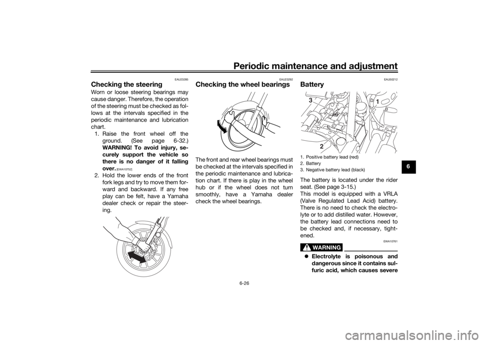
BatteryThe battery is located under the rider
seat. (See page 3-15.)
This model is equipped with a VRLA
(Valve Regulated Lead Acid) battery.
There is no need to check the electro-
lyte or to add distilled water. However,
the battery lead connections need to
be checked and, if necessary, tight-
ened.
WARNING
EWA10761
Electrolyte is poisonous an d
d an gerous since it contains sul-
furic aci d, which causes severe1. Positive battery lead (red)
2. Battery
3. Negative battery lead (black)
1
2
3
UBS5E0E0.book Page 26 Wedne
sday, October 19, 2016 10:21 AM
Page 68 of 88

Periodic maintenance an d a djustment
6-27
6 b
urns. Avoi d any contact with
skin, eyes or clothin g an d al-
ways shiel d your eyes when
workin g near b atteries. In case
of contact, ad minister the fol-
lowin g FIRST AID.
EXTERNAL: Flush with plenty of water.
INTERNAL: Drink lar ge quan-
tities of water or milk an d im-
me diately call a physician.
EYES: Flush with water for 15 minutes an d seek prompt
me dical attention.
Batteries pro duce explosive hy-
d ro gen gas. Therefore, keep
sparks, flames, ci garettes, etc.,
away from the battery an d pro-
vi de sufficient ventilation when
char gin g it in an enclose d
space.
KEEP THIS AND ALL BATTER-
IES OUT OF THE REACH OF
CHILDREN.
To char ge the battery
Have a Yamaha dealer charge the bat-
tery as soon as possible if it seems to
have discharged. Keep in mind that the battery tends to discharge more quick-
ly if the vehicle is equipped with op-
tional electrical accessories.
NOTICE
ECA16522
To char
ge a VRLA (Valve Re gulate d
Lea d Aci d) battery, a special (con-
stant-volta ge) battery char ger is re-
quire d. Usin g a conventional battery
char ger will damag e the b attery.To store the battery
1. If the vehicle will not be used for more than one month, remove the
battery, fully charge it, and then
place it in a cool, dry place.
NOTICE: When removin g the
b attery, be sure to turn the main
switch off, then disconnect the
ne gative lea d before discon-
nectin g the positive lea d.
[ECA16304]
2. If the battery will be stored for
more than two months, check it at
least once a month and fully char-
ge it if necessary.
3. Fully charge the battery before installation. NOTICE: When in-
stallin g the battery, be sure to
turn the main switch off, then connect the positive lea
d b efore
connectin g the ne gative lea d.
[ECA16842]
4. After installation, make sure that
the battery leads are properly con-
nected to the battery terminals.NOTICE
ECA16531
Always keep the b attery charged .
Storin g a d ischar ged battery can
cause permanent battery damag e.
UBS5E0E0.book Page 27 Wedne sday, October 19, 2016 10:21 AM
Page 69 of 88
Periodic maintenance an d a djustment
6-28
6
EAU57711
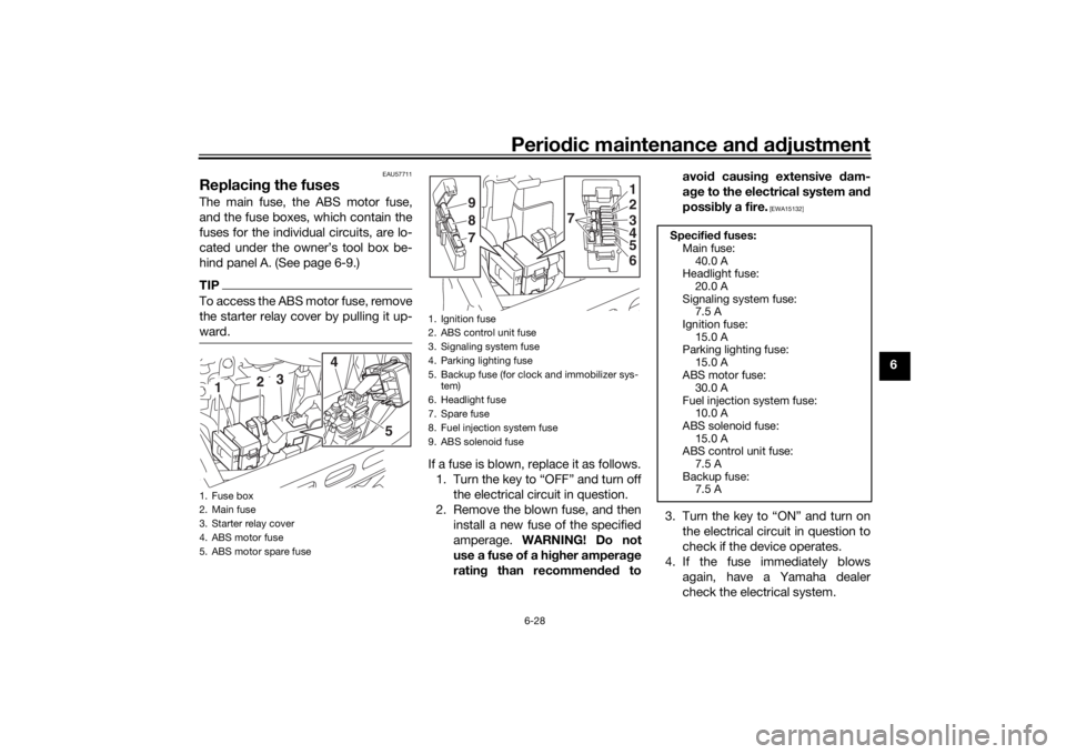
Replacin g the fusesThe main fuse, the ABS motor fuse,
and the fuse boxes, which contain the
fuses for the individual circuits, are lo-
cated under the owner’s tool box be-
hind panel A. (See page 6-9.)TIPTo access the ABS motor fuse, remove
the starter relay cover by pulling it up-
ward.
If a fuse is blown, replace it as follows.
1. Turn the key to “OFF” and turn off the electrical circuit in question.
2. Remove the blown fuse, and then install a new fuse of the specified
amperage. WARNING! Do not
use a fuse of a hi gher ampera ge
ratin g than recommen ded to avoi
d causin g extensive dam-
a g e to the electrical system an d
possi bly a fire.
[EWA15132]
3. Turn the key to “ON” and turn on
the electrical circuit in question to
check if the device operates.
4. If the fuse immediately blows again, have a Yamaha dealer
check the electrical system.
1. Fuse box
2. Main fuse
3. Starter relay cover
4. ABS motor fuse
5. ABS motor spare fuse
3
2
1
4
5
1. Ignition fuse
2. ABS control unit fuse
3. Signaling system fuse
4. Parking lighting fuse
5. Backup fuse (for clock and immobilizer sys-tem)
6. Headlight fuse
7. Spare fuse
8. Fuel injection system fuse
9. ABS solenoid fuse
2 1
4
5
6
7
789
3
Specified
fuses:
Main fuse: 40.0 A
Headlight fuse:
20.0 A
Signaling system fuse: 7.5 A
Ignition fuse: 15.0 A
Parking lighting fuse:
15.0 A
ABS motor fuse: 30.0 A
Fuel injection system fuse: 10.0 A
ABS solenoid fuse:
15.0 A
ABS control unit fuse: 7.5 A
Backup fuse: 7.5 A
UBS5E0E0.book Page 28 Wedne sday, October 19, 2016 10:21 AM
Page 70 of 88

Periodic maintenance an d a djustment
6-29
6
EAU63180
Replacin g the hea dlig ht bul bThis model is equipped with a halogen
bulb headlight. If the headlight bulb
burns out, replace it as follows.NOTICE
ECA10661
Do not touch the g lass part of the
hea dlig ht bul b to keep it free from
oil, otherwise the transparency of
the glass, the luminosity of the bul b,
an d the bul b life will b e adversely af-
fected . Thorou ghly clean off any d irt
an d fin gerprints on the hea dlig ht
b ul b usin g a cloth moistene d with al-
cohol or thinner.1. Remove the headlight unit by re- moving the screws. 2. Disconnect the headlight coupler,
and then remove the headlight
bulb cover.
3. Unhook the headlight bulb holder, and then remove the burnt-out
bulb. 4. Place a new headlight bulb into
position, and then secure it with
the bulb holder.
5. Install the bulb cover, and then connect the coupler.
TIPWhen installing the headlight bulb cov-
er, make sure the “TOP” mark faces
upwards.
1. Do not touch the glass part of the bulb.
1. Screw
1. Headlight coupler
2. Headlight bulb cover
1
2
1
1. Headlight bulb holder
1
UBS5E0E0.book Page 29 Wedne sday, October 19, 2016 10:21 AM