YAMAHA YBR125 2004 User Guide
Manufacturer: YAMAHA, Model Year: 2004, Model line: YBR125, Model: YAMAHA YBR125 2004Pages: 83, PDF Size: 3.16 MB
Page 11 of 83

CONTENTS
DESCRIPTION............................................................. 1-1
MACHINE IDENTIFICATION....................................... 2-1
Vehicle identification number ................................. 2-1
Engine serial number............................................ 2-1
CONTROL FUNCTIONS.............................................. 3-1
Main switch ............................................................ 3-1
Indicator lights ........................................................ 3-2
Speedometer..........................................................3-3
Fuel gauge............................................................. 3-3
Handlebar switches over left .................................. 3-4
Handlebar switches over right.............................. 3-5
Clutch lever............................................................ 3-6
Shift pedal............................................................. 3-6
Front brake lever................................................... 3-7
Rear brake pedal................................................... 3-7
Fuel tank cap......................................................... 3-8
Fuel cock............................................................... 3-9
Starter lever......................................................... 3-10
Kick starter .......................................................... 3-10
Steering lock....................................................... 3-11
Seat......................................................................3-12
Side covers......................................................... 3-13
Rear shock absorber adjustment ....................... 3-14
XIPRE-OPERATION CHECKS........................................ 4-1
Engine oil................................................................ 4-3
Tires........................................................................4-3
Fitting/Fasteners....................................................4-6
Switches................................................................ 4-6
Wheels ......................................................... 4-6
Fuel ........................................................... 4-7
OPERATION AND IMPORTANT RIDING POINTS....... 5-1
Starting a cold engine........................................... 5-2
Starting a warm engine .......................................... 5-2
Warming up the engine .......................................... 5-2
Shifting ................................................................... 5-3
Tips for reduccing fuel consumption...................... 5-4
Engine Break-in...................................................... 5-4
Parking ................................................................... 5-5
Page 12 of 83
PERIODIC MAINTENANCE AND MINOR REPAIRS..... 6-1
Tool kit..................................................................... 6-2
PERIODIC MAINTENANCE/LUBRICATION......... 6-3
Torque specifications............................................. 6-5
Engine oil................................................................ 6-6
Oil pressure............................................................ 6-9
Air filter.................................................................6-10
Carburetor adjustment.........................................6-12
Valve clearance adjustment.................................6-12
Idle speed adjustment..........................................6-13
Throttle cable adjustment....................................6-14
Spark plug inspection...........................................6-15
Front brake adjustment........................................6-16
Checking the brake shoes ...................................6-16
Rear brake adjustment.........................................6-17
Brake light switch adjustment ..............................6-18
Clutch adjustment................................................ 6-18
Drive chain slack check.......................................6-19
Drive chain slack adjustment...............................6-20
Drive chain lubrication..........................................6-21
Cable inspection and lubrication.......................... 6-21
Throttle cable and grip lubrication .......................6-22
Brake and shift pedals .........................................6-22
Brake and clutch levers .......................................6-22
Sidestand.............................................................6-22
Front fork inspection............................................6-23Steering inspection.............................................. 6-24
Wheel bearings.................................................... 6-24
Battery.................................................................. 6-25
Replenishing the battery fluid .............................. 6-26
Storage the battery.............................................. 6-27
Fuse replacement................................................ 6-27
Headlight bulb replacement................................. 6-28
Turn signal bulb replacement.............................. 6-30
Taillight bulb replacement.................................... 6-30
Front wheel removal............................................. 6-31
Front wheel installation........................................ 6-32
Rear wheel removal............................................. 6-32
Rear wheel installation......................................... 6-33
Troubleshooting.................................................... 6-34
Troubleshooting chart.......................................... 6-35
CLEANING AND STORAGE....................................... 7-1
CLEANING............................................................. 7-1
STORAGE.............................................................. 7-2
SPECIFICATIONS ........................................................ 8-1
XII
CONTENTS
DESCRIPTION............................................................. 1-1
MACHINE IDENTIFICATION....................................... 2-1
Vehicle identikfication number ............................... 2-1
Engine serial number............................................ 2-1
CONTROL FUNCTIONS.............................................. 3-1
Main switch ............................................................ 3-1
Indicator lights ........................................................ 3-2
Speedometer..........................................................3-3
Fuel gauge............................................................. 3-3
Handlebar switches over left .................................. 3-4
Handlebar switches over right.............................. 3-5
Clutch lever............................................................ 3-6
Shift pedal............................................................. 3-6
Front brake lever................................................... 3-7
Rear brake pedal................................................... 3-7
Fuel tank cap......................................................... 3-8
Fuel cock............................................................... 3-9
Starter lever......................................................... 3-10
Kick starter .......................................................... 3-10
Steering lock....................................................... 3-11
Seat......................................................................3-12
Side covers......................................................... 3-13
Rear shock absorber adjustment ....................... 3-14
XIPRE-OPERATION CHECKS........................................ 4-1
Engine oil................................................................ 4-3
Tires........................................................................4-3
Fitting/Fasteners....................................................4-6
Switches................................................................ 4-6
Wheels ......................................................... 4-6
Fuel ........................................................... 4-7
OPERATION AND IMPORTANT RIDING POINTS....... 5-1
Starting a cold engine........................................... 5-2
Starting a warm engine .......................................... 5-2
Warming up the engine .......................................... 5-2
Shifting ................................................................... 5-3
Tips for reduccing fuel consumption...................... 5-4
Engine Break-in...................................................... 5-4
Parking ................................................................... 5-5
Page 13 of 83
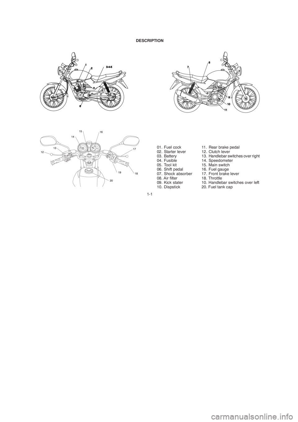
1-1 DESCRIPTION
01. Fuel cock
02. Starter lever
03. Battery
04. Fusible
05. Tool kit
06. Shift pedal
07. Shock absorber
08. Air filter
09. Kick stater
10. Dispstick11. Rear brake pedal
12. Clutch lever
13. Handlebar switches over right
14. Speedometer
15. Main switch
16. Fuel gauge
17. Front brake lever
18. Throttle
10. Handlebar switches over left
20. Fuel tank cap
Page 14 of 83
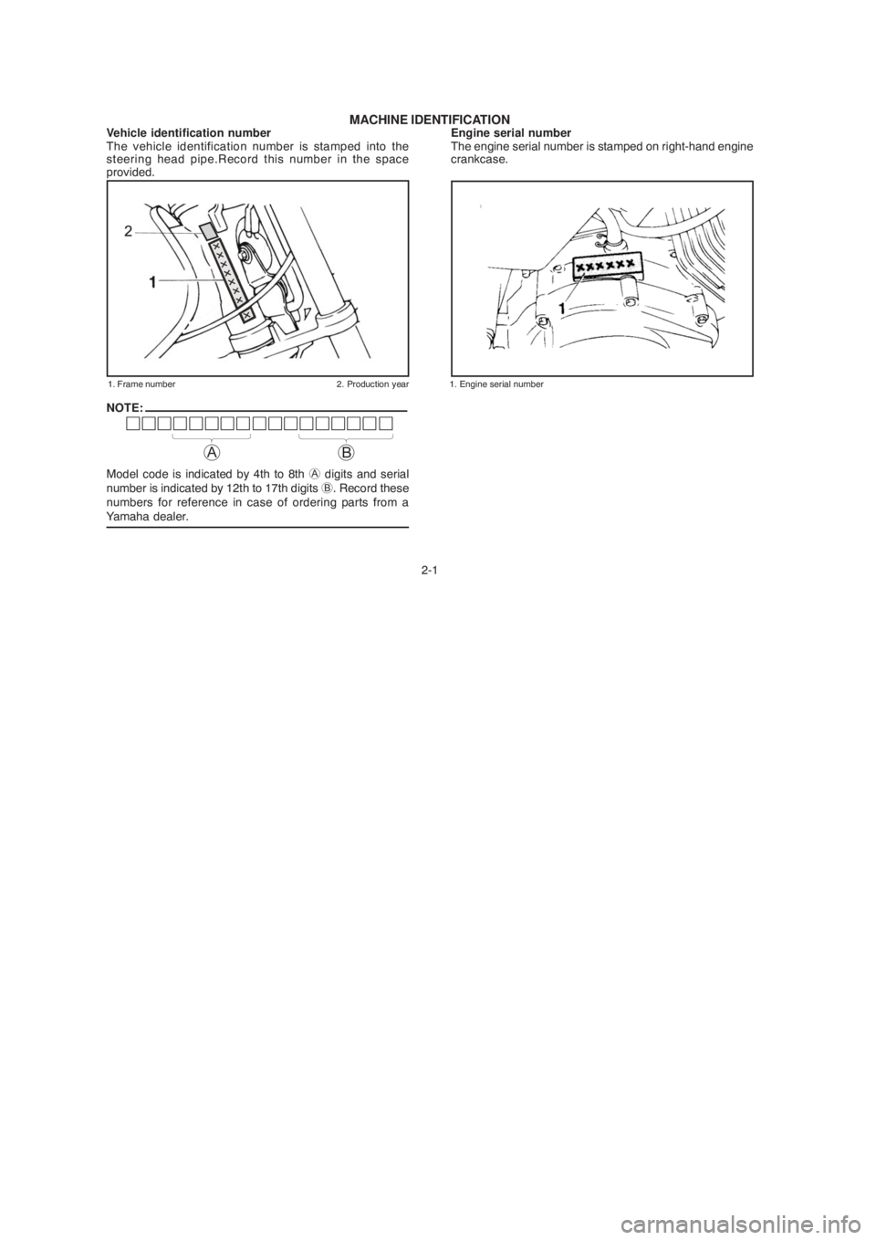
2-1 Vehicle identification number
The vehicle identification number is stamped into the
steering head pipe.Record this number in the space
provided.
1. Frame number 2. Production year
Engine serial number
The engine serial number is stamped on right-hand engine
crankcase.
1. Engine serial number
NOTE:
Model code is indicated by 4th to 8th A digits and serial
number is indicated by 12th to 17th digits B. Record these
numbers for reference in case of ordering parts from a
Yamaha dealer.
MACHINE IDENTIFICATION
AB
Page 15 of 83
3-1
CONTROL FUNCTIONS
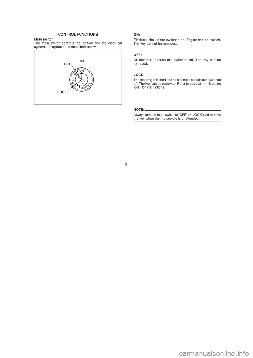
Main switch
The main switch controls the ignition and the electrical
system. Itís operation is described below.
ON:
Electrical circuits are switched on. Engine can be started.
The key cannot be removed.
OFF:
All electrical circuits are switched off. The key can be
removed.
LOCK:
The steering is locked and all electrical circuits are switched
off. The key can be removed. Refer to page (3-11) ìSteering
lockî for instructions.
NOTE:
Always turn the main switch to ìOFFî or ìLOCKî and remove
the key when the motorcycle is unattended.
Page 16 of 83
3-2
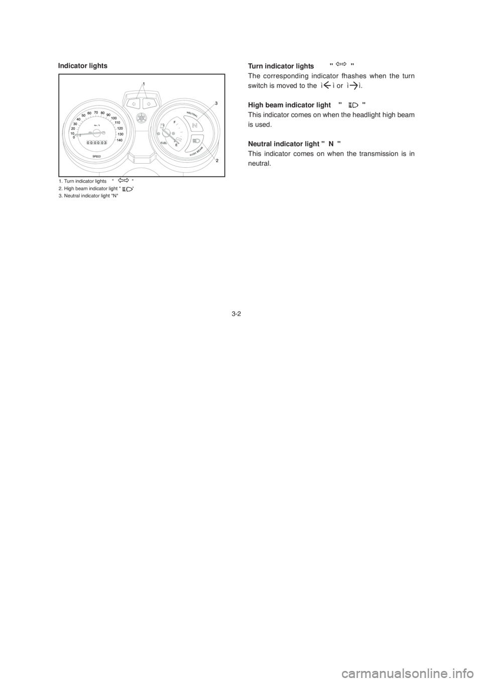
Turn indicator lights " "
The corresponding indicator fhashes when the turn
switch is moved to the ì ì or ì ì.
High beam indicator light "
"
This indicator comes on when the headlight high beam
is used.
Neutral indicator light " N "
This indicator comes on when the transmission is in
neutral. Indicator lights
1. Turn indicator lights " "
2. High beam indicator light " "
3. Neutral indicator light "N"
Page 17 of 83
Fuel gauge
Speedometer
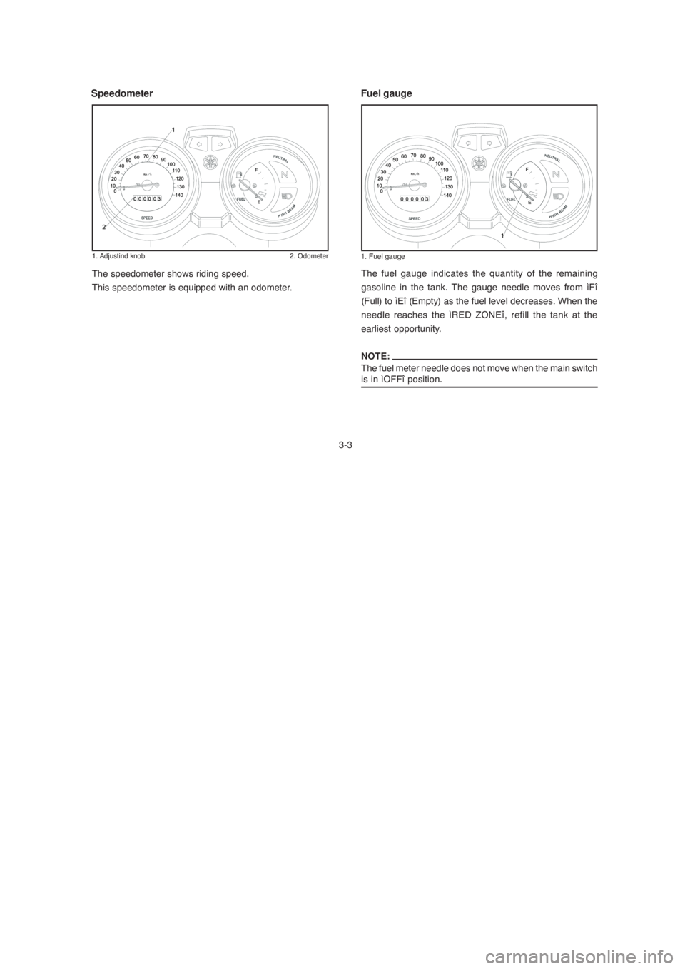
3-3The fuel gauge indicates the quantity of the remaining
gasoline in the tank. The gauge needle moves from ìFî
(Full) to ìEî (Empty) as the fuel level decreases. When the
needle reaches the ìRED ZONEî, refill the tank at the
earliest opportunity.
NOTE:
The fuel meter needle does not move when the main switch
is in ìOFFî position. The speedometer shows riding speed.
This speedometer is equipped with an odometer.
1. Adjustind knob 2. Odometer1. Fuel gauge
Page 18 of 83
Handlebar switches over left
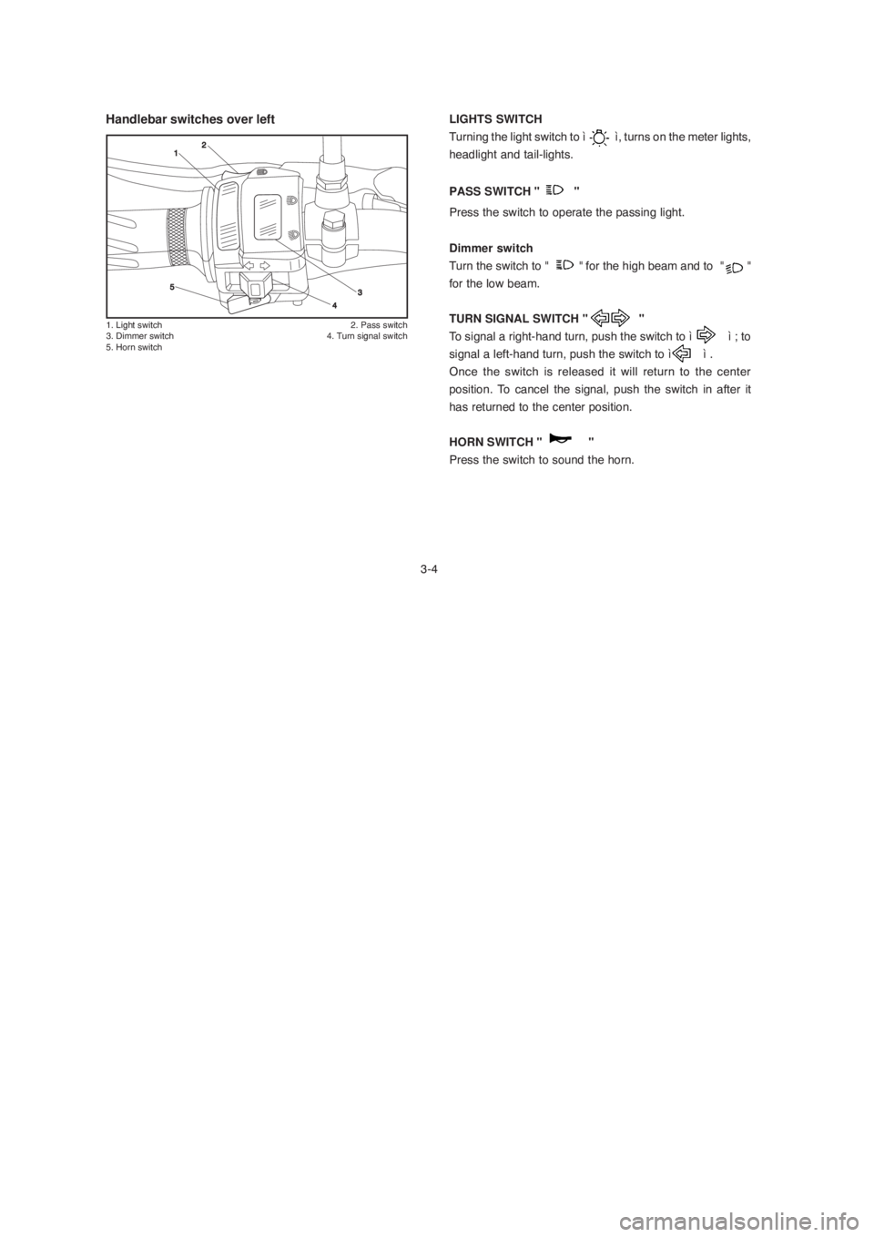
1. Light switch 2. Pass switch
3. Dimmer switch 4. Turn signal switch
5. Horn switch
3-4LIGHTS SWITCH
Turning the light switch to ì ì, turns on the meter lights,
headlight and tail-lights.
PASS SWITCH " "
Press the switch to operate the passing light.
Dimmer switch
Turn the switch to " " for the high beam and to " "
for the low beam.
TURN SIGNAL SWITCH " "
To signal a right-hand turn, push the switch to ì ì ; to
signal a left-hand turn, push the switch to ì ì .
Once the switch is released it will return to the center
position. To cancel the signal, push the switch in after it
has returned to the center position.
HORN SWITCH " "
Press the switch to sound the horn.
Page 19 of 83
Handlebar switches over rigt
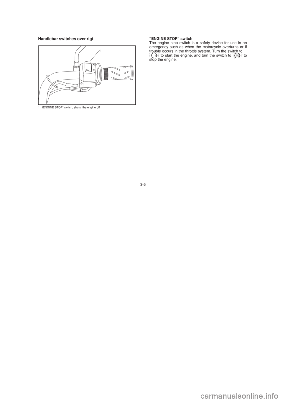
1. ìENGINE STOPî switch, shuts the engine off
3-5“ENGINE STOP” switch
The engine stop switch is a safety device for use in an
emergency such as when the motorcycle overturns or if
trouble occurs in the throttle system. Turn the switch to
ì î to start the engine, and turn the switch to ì î to
stop the engine.
Page 20 of 83
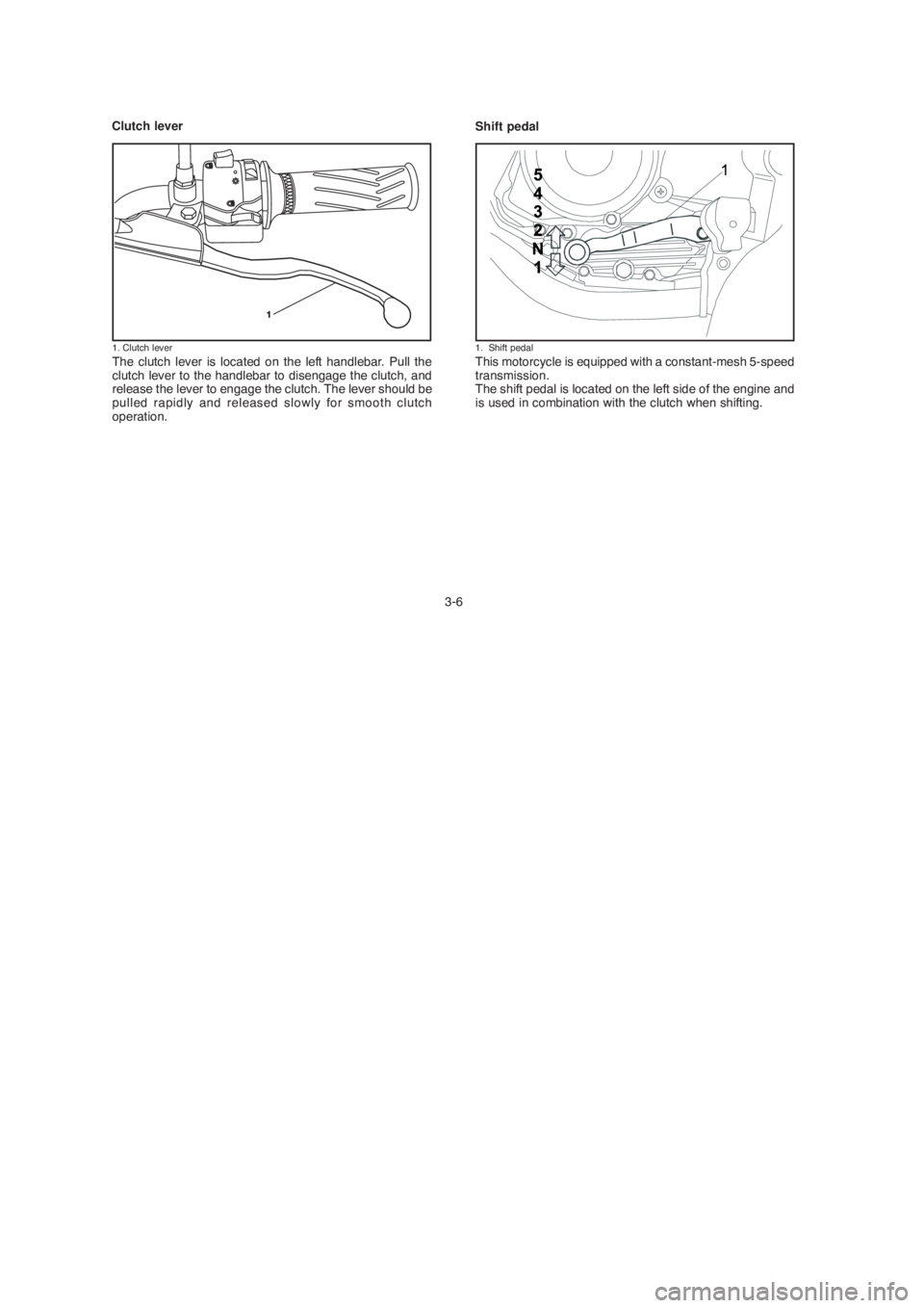
The clutch lever is located on the left handlebar. Pull the
clutch lever to the handlebar to disengage the clutch, and
release the lever to engage the clutch. The lever should be
pulled rapidly and released slowly for smooth clutch
operation.
3-6This motorcycle is equipped with a constant-mesh 5-speed
transmission.
The shift pedal is located on the left side of the engine and
is used in combination with the clutch when shifting.
Clutch lever
Shift pedal
1. Clutch lever1. Shift pedal