Shift YAMAHA YXZ1000R SS 2020 Owners Manual
[x] Cancel search | Manufacturer: YAMAHA, Model Year: 2020, Model line: YXZ1000R SS, Model: YAMAHA YXZ1000R SS 2020Pages: 212, PDF Size: 9.36 MB
Page 6 of 212

EBU31120
CONTENTS
VEHICLE IDENTIFICATION ..................... 1-1Identification numbers .......................... 1-1
LOCATION OF THE WARNING AND
SPECIFICATION LABELS ....................... 2-1
SAFETY INFORMATION ......................... 3-1
DESCRIPTION......................................... 4-1 Left view ............................................... 4-1
Right view ............................................. 4-2
Controls and instruments ..................... 4-3
INSTRUMENT AND CONTROL
FUNCTIONS............................................ 5-1 Main switch .......................................... 5-1
Indicator lights and warning lights ....... 5-2
Multi-function meter unit .................... 5-10
Light switch ........................................ 5-19
Interior light switch (equipped models) ............................ 5-20 On–Command drive knob
“2WD/4WD/DIFF LOCK” .................. 5-21
Accelerator pedal ............................... 5-21
Brake pedal ........................................ 5-22
Parking brake lever ............................ 5-22
YCC-S system.................................... 5-23
Drive select lever and shift paddles ... 5-24
Fuel tank cap...................................... 5-25
Doors .................................................. 5-25
Seats .................................................. 5-25
Adjusting the driver seat position....... 5-27
Adjusting the steering wheel position ............................................. 5-27
Seat belts ........................................... 5-28
Glove compartment ........................... 5-29
Storage compartments ...................... 5-29
Cup holders ........................................ 5-30
Cargo bed .......................................... 5-31
Flag pole bracket ............................... 5-32
Front shock absorbers ....................... 5-32
Rear shock absorbers ........................ 5-41
Auxiliary DC jack ................................ 5-49UBAS7AE0.book Page 1 Wednesday, June 19, 2019 11:51 AM
Page 7 of 212

FOR YOUR SAFETY –
PRE-OPERATION CHECKS .................... 6-1Front and rear brakes ........................... 6-3
Fuel ....................................................... 6-3
Engine oil .............................................. 6-5
Transmission ........................................ 6-6
Coolant ................................................. 6-6
Final gear .............................................. 6-6
Differential gear .................................... 6-6
Accelerator pedal ................................. 6-6
Seat belts ............................................. 6-7
Passenger handhold ............................ 6-7
Steering ................................................ 6-7
Drive select lever and shift paddles ..... 6-7
YCC-S clutch ....................................... 6-8
Fittings and fasteners ........................... 6-8
Instruments, lights and switches .......... 6-8
Control cables ...................................... 6-8
Tires ...................................................... 6-8
OPERATION ............................................ 7-1 Engine break-in .................................... 7-1
Starting the engine ............................... 7-2 Shifting and reverse driving ..................7-3
Dynamic clutch engagement ................7-7
Launch system operation .....................7-7
Selecting the drive mode ....................7-10
Parking ................................................7-12
Loading ...............................................7-12
BASIC GUIDE FOR SAFE USE ...............8-1 KNOW YOUR VEHICLE ........................8-1
LEARNING TO OPERATE YOUR VEHICLE ...........................................8-12
PERIODIC MAINTENANCE AND
ADJUSTMENT .........................................9-1 Owner’s Manual and tool kit .................9-2
Maintenance charts ..............................9-4
Hood ...................................................9-11
Panels .................................................9-11
Engine oil and oil filter.........................9-18
Why Yamalube....................................9-28
Transmission oil ..................................9-29
Final gear oil .......................................9-31
Differential gear oil ..............................9-34UBAS7AE0.book Page 2 Wednesday, June 19, 2019 11:51 AM
Page 18 of 212

2-7
2
YAMAHABAS-F4897-00
WARNING
Load may affect handling and stability.
Do not exceed the maximum load ratings for thecargo bed, or vehicle.
When loaded with cargo: Reduce speed and allow more room to stop.
Turn gradually and slowly.
Avoid hills and rough terrain. Secure cargo so that it will not shift - a loose loadcould change handling unexpectedly or be thrown
forward and strike occupants.
Keep weight in the cargo bed centered side to side and as low as possible. Top-heavy loads increase the risk of a
rollover.
Read Owner’s Manual before loading cargo bed. Improper use of cargo bed or
cage/frame can result
in severe injury or
death from loss of
control, overturn or
other accidents.
Maximum Load in Cargo Bed: 300 lbs (136 kg)
Maximum Vehicle Load: 723 lbs (328 kg) Never carry
passengers
in cargo bed.
YAMAHA
BAS-F1696-10
WARNING
Improper tire pressure or overloading this vehicle may
cause severe injury or death from loss of control or
rollover.Never set or allow tire pressure to be below the minimum.
Tire may dislodge from rim. VEHICLE LOAD of 0 kg (0 lb) ~ 195 kg (430 lbs)
Recommended: FRONT: REAR:
Minimum: FRONT: REAR:114 kPa
128 kPa
110 kPa
124 kPa
VEHICLE LOAD of 195 kg (430 lbs) ~ 328 kg (723 lbs)Recommended: FRONT: REAR:
Minimum: FRONT: REAR:114 kPa
169 kPa
110 kPa
165 kPa (16.5 psi)
(18.5 psi)
(16 psi)
(18 psi)
(16.5 psi)
(24.5 psi)
(16 psi)
(24 psi)
* Vehicle load is weight of operator, passenger, accessories, and cargo. Do not exceed
maximum vehicle load.
Gross Vehicle Weight Rating: 1065 kg (2348 lbs)
maximum including vehicle, weight of operator,
passenger, accessories, and cargo.OPERATING TIRE PRESSURE: With tires cold, set as follows.
10
9
UBAS7AE0.book Page 7 Wednesday, June 19, 2019 11:51 AM
Page 24 of 212

3-3
3
• Do not drive or ride as passenger after using drugs or alcohol.
Prepare your vehicle
Perform the pre-operation checks each time you use the vehicle to make sure it is in safe oper-
ating condition. Failure to inspect or maintain th e vehicle properly increases the possibility of an
accident or equipment damage. See page 6-1 for a list of pre-operation checks.
Prepare your load
Carrying heavy or over-sized loads can affect hand ling, stability, and cause the risk of overturns
or other accidents.
Read “Loading” on page 7-12 before loading the cargo bed.
Do not overload the vehicle or cargo bed.
Refer to the labels on the vehicle for specific loading limits and recommended tire air pressure.
Keep heavier objects and the load in general cent ered side to side, and as low and as far for-
ward in the cargo bed as possible.
Secure cargo so that it will not shift – a loose load could change handling unexpectedly or be
thrown forward and strike occupants.
This vehicle is not designed to tow or pull objects. Towing a trailer or pulling another vehicle or
other object will affect handling, stability, an d increase the risk of overturns and accidents.
Towing or pulling can also cause frame and vehicle damage.
UBAS7AE0.book Page 3 Wednesday, June 19, 2019 11:51 AM
Page 32 of 212

4-3
4
EBU31200Controls and instrumentsThe vehicle you have purchased may differ slightly from those shown in the figures of this man-
ual.
36
78
9
1
2
45
14
12
10,11
15 13
1. Steering wheel
2. Shift paddle “ ”
3. Multi-function meter unit
4. Shift paddle “ ”
5. Main switch
6. Drive select lever
7. Parking brake lever
8. Interior light switch (equipped models)
9. Passenger handhold
10.Helmet reminder light
11.Seat belt reminder light
12.Light switch
13.On-Command drive knob
14.Accelerator pedal
15.Brake pedal
UBAS7AE0.book Page 3 Wednesday, June 19, 2019 11:51 AM
Page 34 of 212
5-2
5
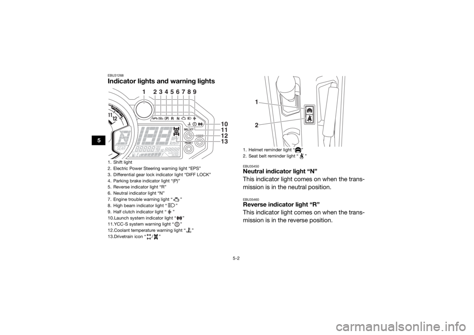
EBU31268Indicator lights and warning lights
EBU35450Neutral indicator light “N”
This indicator light comes on when the trans-
mission is in the neutral position.EBU35460Reverse indicator light “R”
This indicator light comes on when the trans-
mission is in the reverse position.
1. Shift light
2. Electric Power Steering warning light “EPS”
3. Differential gear lock indicator light “DIFF LOCK”
4. Parking brake indicator light “(P)”
5. Reverse indicator light “R”
6. Neutral indicator light “N”
7. Engine trouble warning light “ ”
8. High beam indicator light “ ”
9. Half clutch indicator light “ ”
10.Launch system indicator light “ ”
11.YCC-S system warning light “ ”
12.Coolant temperature warning light “ ”
13.Drivetrain icon “ / ”
1
2
3
4
5
6
7
8
9
10111213
1. Helmet reminder light “ ”
2. Seat belt reminder light “ ”
12
UBAS7AE0.book Page 2 Wednesday, June 19, 2019 11:51 AM
Page 36 of 212
5-4
5
and/or turn the steering wheel back and
forth to help the differential to lock or un-
lock. EBU34932Shift light
This light can be set to come on and go off at
the desired engine speeds and is used to in-
form the driver when it is time to upshift.
The electrical circuit of the shift light can be
checked by turning the key to “ ” (on). If the
light does not come on initially when the key
is turned to “ ” (on), or if the light remains
on, have a Yamaha dealer check the electrical
circuit.TIPSee page 5-16 for an explanation of how to
set the shift light.
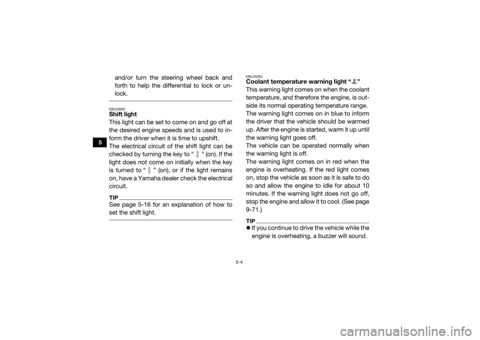
EBU35283Coolant temperature warning light “ ”
This warning light comes on when the coolant
temperature, and therefore the engine, is out-
side its normal operating temperature range.
The warning light comes on in blue to inform
the driver that the vehicle should be warmed
up. After the engine is started, warm it up until
the warning light goes off.
The vehicle can be operated normally when
the warning light is off.
The warning light comes on in red when the
engine is overheating. If the red light comes
on, stop the vehicle as soon as it is safe to do
so and allow the engine to idle for about 10
minutes. If the warning light does not go off,
stop the engine and allow it to cool. (See page
9-71.)TIPIf you continue to drive the vehicle while the
engine is overheating, a buzzer will sound.
UBAS7AE0.book Page 4 Wednesday, June 19, 2019 11:51 AM
Page 38 of 212
5-6
5
started, the EPS system may not be working
correctly. When this occurs, have a Yamaha
dealer check the EPS system.
The electrical circuit of the warning light can
be checked by turning the key to “ ” (on). If
the warning light does not come on, have a
Yamaha dealer check the electrical circuit.TIPIf the steering load is too heavy (e.g., exces-
sive steering use at slow speed or when op-
erating in deep mud, sand, or snow), the
power assist is reduced to protect the EPS
motor from overheating. EBU36713Half clutch indicator light “ ”
This indicator light comes on to inform the
driver when the clutch is partially engaged.
Normal, temporary partial-engagement oc-
curs when starting off or when shifting gears.
The indicator light may also come on during
engine braking or in other situations. The electrical circuit of the indicator light can
be checked by turning the key to “ ” (on). If
the indicator light does not come on and then
go off, have a Yamaha dealer check the elec-
trical circuit.
TIPIf the indicator light stays on while driving, ei-
ther release the accelerator pedal or further
press down the accelerator pedal (release or
increase throttle) to fully engage or disengage
the clutch. NOTICEECB03351Do not use the throttle (accelerator pedal)
to hold the vehicle stationary when on an
incline or navigating obstacles. Continu-
ous operation while the indicator light is on
may lead to shortened clutch life.
UBAS7AE0.book Page 6 Wednesday, June 19, 2019 11:51 AM
Page 39 of 212
5-7
5
EBU36643Launch system indicator light “ ”
This indicator light comes on when the launch
system is activated. If the indicator light is
flashing, either a user error or system restric-
tion has been detected. See “Launch system
operation” on page 7-7 for more information.
The electrical circuit of the indicator light can
be checked by turning the key to “ ” (on). If
the indicator light does not come on and then
go off, have a Yamaha dealer check the elec-
trical circuit.TIPIf the launch system indicator light is flashing,
release the accelerator pedal and shift pad-
dles to reset the system. When the engine
speed returns to idle, the indicator light will go
off. You can now start off as normal in first
gear, or retry activating the launch system.
EBU36743YCC-S system warning light “ ”
This warning light comes on when an error
has occurred or a malfunction has been de-
tected in the YCC-S system. Have a Yamaha
dealer check the YCC-S system.
The electrical circuit of the YCC-S system
warning light can be checked by turning the
key to “ ” (on). If the warning light does not
come on and then go off, have a Yamaha
dealer check the electrical circuit.
If the YCC-S system warning light flashes
when starting the engine, wait 3 seconds for
the light to stop flashing, and then retry start-
ing the engine. If an error in the YCC-S sys-
tem prevents the engine from starting, the
warning light will come and the display will in-
dicate an error code.TIPYCC-S system error codes are visible only
when the engine is stopped.
UBAS7AE0.book Page 7 Wednesday, June 19, 2019 11:51 AM
Page 40 of 212
5-8
5
The engine may not start even though the
starter motor operates. If the YCC-S system stops working correctly
while driving, the YCC-S warning light will
come on. If this occurs, it may be impossible
to shift out of the gear you are in; and the
clutch may stay engaged, so a shuddering
sensation may be felt when you come to a
stop. Stop the vehicle on level ground safely
off the main trail, and have the YCC-S system
serviced by a Yamaha dealer before further
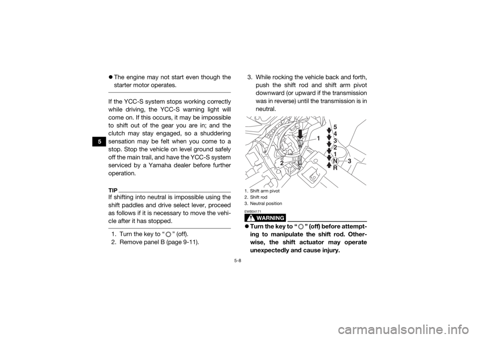
operation.TIPIf shifting into neutral is impossible using the
shift paddles and drive select lever, proceed
as follows if it is nece ssary to move the vehi-
cle after it has stopped. 1. Turn the key to “ ” (off).
2. Remove panel B (page 9-11). 3. While rocking the vehicle back and forth,
push the shift rod and shift arm pivot
downward (or upward if the transmission
was in reverse) until the transmission is in
neutral.
WARNING
EWB04171Turn the key to “ ” (off) before attempt-
ing to manipulate the shift rod. Other-
wise, the shift actuator may operate
unexpectedly and cause injury.1. Shift arm pivot
2. Shift rod
3. Neutral position
1
2
3
5 5
4
3
2
1
N
R 5
4
3
2
1
N
R
UBAS7AE0.book Page 8 Wednesday, June 19, 2019 11:51 AM