clock YAMAHA YXZ1000R SS 2020 Owners Manual
[x] Cancel search | Manufacturer: YAMAHA, Model Year: 2020, Model line: YXZ1000R SS, Model: YAMAHA YXZ1000R SS 2020Pages: 212, PDF Size: 9.36 MB
Page 42 of 212

5-10
5
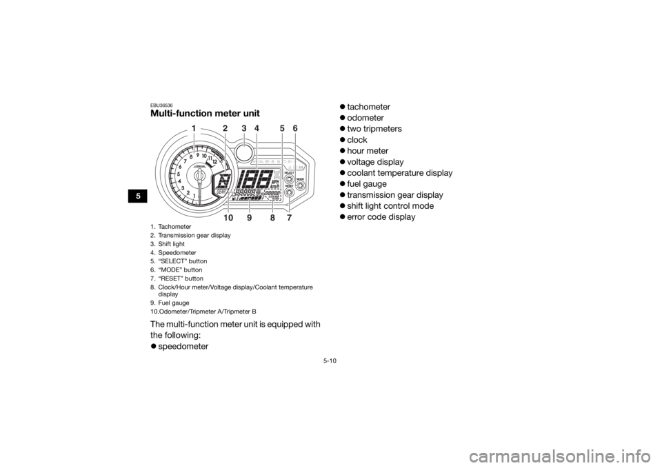
EBU36536Multi-function meter unitThe multi-function meter unit is equipped with
the following:
speedometer
tachometer
odometer
two tripmeters
clock
hour meter
voltage display
coolant temperature display
fuel gauge
transmission gear display
shift light control mode
error code display1. Tachometer
2. Transmission gear display
3. Shift light
4. Speedometer
5. “SELECT” button
6. “MODE” button
7. “RESET” button
8. Clock/Hour meter/Voltage display/Coolant temperature
display
9. Fuel gauge
10.Odometer/Tripmeter A/Tripmeter B
123456
10 9 87
UBAS7AE0.book Page 10 Wednesday, June 19, 2019 11:51 AM
Page 45 of 212

5-13
5
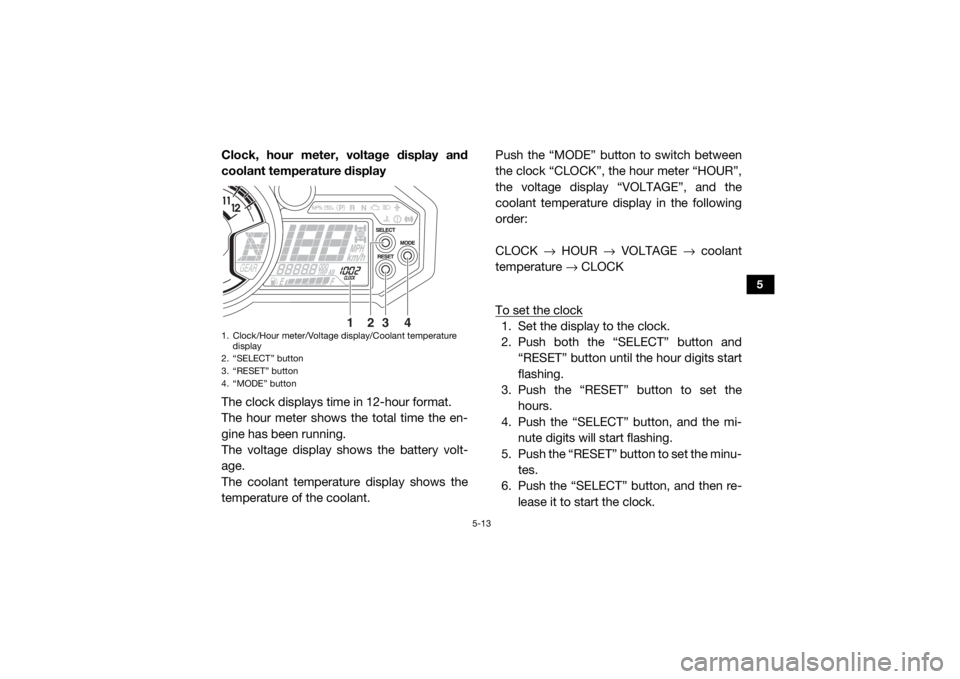
Clock, hour meter, voltage display and
coolant temperature display
The clock displays time in 12-hour format.
The hour meter shows the total time the en-
gine has been running.
The voltage display shows the battery volt-
age.
The coolant temperature display shows the
temperature of the coolant.Push the “MODE” button to switch between
the clock “CLOCK”, the hour meter “HOUR”,
the voltage display “VOLTAGE”, and the
coolant temperature display in the following
order:
CLOCK
→ HOUR → VOLTAGE → coolant
temperature → CLOCK
To set the clock
1. Set the display to the clock.
2. Push both the “SELECT” button and “RESET” button until th e hour digits start
flashing.
3. Push the “RESET” button to set the
hours.
4. Push the “SELECT” button, and the mi- nute digits will start flashing.
5. Push the “RESET” button to set the minu- tes.
6. Push the “SELECT” button, and then re-
lease it to start the clock.
1. Clock/Hour meter/Voltage display/Coolant temperature display
2. “SELECT” button
3. “RESET” button
4. “MODE” button
1
2
3
4
UBAS7AE0.book Page 13 Wednesday, June 19, 2019 11:51 AM
Page 57 of 212

5-25
5
EBU31451Fuel tank capRemove the fuel tank cap when refueling. To
open, turn counterclockwise. When finished
refueling, install the fuel tank cap by screwing
it down clockwise.EBU37390DoorsThe door handle is located on the inside of
each door. To open a door, pull the handle. To close a
door, push or pull the door inward until it is
securely latched. Be sure the door is SE-
CURELY LATCHED AFTER CLOSING IT.
EBU33461SeatsTo remove a seat cushion, lift the front of the
cushion, and then pu
ll the cushion off.
1. Fuel tank cap
1
1. Door
2. Handle
1
2
UBAS7AE0.book Page 25 Wednesday, June 19, 2019 11:51 AM
Page 143 of 212

9-16
9
Place the passenger seat belt in the original
position. 3. Install the passenger seat cushion.
4. Install the top cover by installing the bolts
and quick fastener screw.
5. Install panel A and the hood.
Panels C and D
To remove a panel1. Pull the tab on the panel lock up, and then turn the panel lock 1/4 turn clock-
wise.
1. Panel C
2. Panel D
3. Tab
1. Tab
2. Panel lock
1
3
2
3
1
2
UBAS7AE0.book Page 16 Wednesday, June 19, 2019 11:51 AM
Page 145 of 212

9-18
9
2. Turn the panel lock 1/4 turn counter-clockwise, and then push the tab on the
p a n e l l o c k d o w n s o t h a t i t i s p o i n t i n g r e a r -
ward.EBU3543AEngine oil and oil filterCheck the engine oil level before each opera-
tion. In addition, change the oil and the oil fil-
ter cartridge at the intervals specified in the
periodic maintenance chart.
NOTICEECB03020 Do not use oils with a diesel specifica-
tion of “CD” or oils of a higher quality
than specified. In addition, do not use
oils labeled “ENERGY CONSERVING II”
or higher.
Make sure that no foreign material en-
ters the oil tank. To check the engine oil level
1. Park the vehicle on a level surface.
2. Remove panel D. (See page 9-11.)
3. Start the engine and warm it up to a nor- mal operating temperature (the engine oil
temperature should reach 60 °C [140 °F]),
then let the engine idle for a minimum of
ten seconds before turning the engine off.TIPIf the engine is cold, take the vehicle for a
short drive or let it idle for approximately ten
minutes before checking the engine oil level.
Recommended engine oil:YA M A L U B E5W-30, 10W-30, 10W-40, 15W-40, 20W-
40, 20W-50
Oil quantity: Oil change only:2.50 L (2.64 US qt, 2.20 Imp.qt)
Oil change and filter replacement: 2.70 L (2.85 US qt, 2.38 Imp.qt)
UBAS7AE0.book Page 18 Wednesday, June 19, 2019 11:51 AM
Page 169 of 212

9-42
9
Additionally, the fuel injection system
would be affected, resulting in poor engine
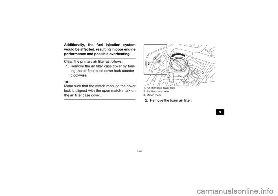
performance and possible overheating. Clean the primary air filter as follows. 1. Remove the air filter case cover by turn- ing the air filter case cover lock counter-
clockwise.TIPMake sure that the match mark on the cover
lock is aligned with the open match mark on
the air filter case cover.
2. Remove the foam air filter.1. Air filter case cover lock
2. Air filter case cover
3. Match mark
1
2
3
UBAS7AE0.book Page 42 Wednesday, June 19, 2019 11:51 AM
Page 171 of 212

9-44
9
6. Wash the foam material in warm soapywater to remove remaining solvent, then
rinse thoroughly with plain warm water.
7. Squeeze out the excess water. NOTICE:
Do not twist the foam material when
squeezing it.
[ECB02970]
8. Allow the foam air filter to dry thoroughly.Inspect for wear and tear and replace if
damaged or heavily worn. 9. Thoroughly apply Yamalube foam air filter
oil (or other quality liquid foam air filter—
do not use a spray-type product) to the
foam material. The foam air filter element
should be wet but not dripping.
10. Pull the foam air filter element over its frame.
11. Install the air filter.
12. Install the air filter case cover and lock it
into place by turning the air filter case
cover lock clockwise.
UBAS7AE0.book Page 44 Wednesday, June 19, 2019 11:51 AM
Page 192 of 212

9-65
9
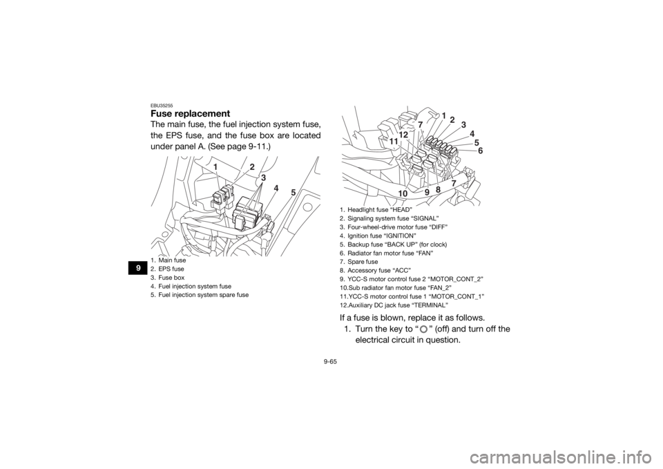
EBU35255Fuse replacementThe main fuse, the fuel injection system fuse,
the EPS fuse, and the fuse box are located
under panel A. (See page 9-11.)If a fuse is blown, replace it as follows.1. Turn the key to “ ” (off) and turn off the electrical circuit in question.1. Main fuse
2. EPS fuse
3. Fuse box
4. Fuel injection system fuse
5. Fuel injection system spare fuse
5
4
3
21
1. Headlight fuse “HEAD”
2. Signaling system fuse “SIGNAL”
3. Four-wheel-drive motor fuse “DIFF”
4. Ignition fuse “IGNITION”
5. Backup fuse “BACK UP” (for clock)
6. Radiator fan motor fuse “FAN”
7. Spare fuse
8. Accessory fuse “ACC”
9. YCC-S motor control fuse 2 “MOTOR_CONT_2”
10.Sub radiator fan motor fuse “FAN_2”
11.YCC-S motor control fuse 1 “MOTOR_CONT_1”
12.Auxiliary DC jack fuse “TERMINAL”
5
6
7
7
12
11
10 98 4
3
2
1
UBAS7AE0.book Page 65 Wednesday, June 19, 2019 11:51 AM