YAMAHA YZ125LC 2012 Owner's Guide
Manufacturer: YAMAHA, Model Year: 2012, Model line: YZ125LC, Model: YAMAHA YZ125LC 2012Pages: 168, PDF Size: 8.27 MB
Page 31 of 168
2-7
TIGHTENING TORQUES
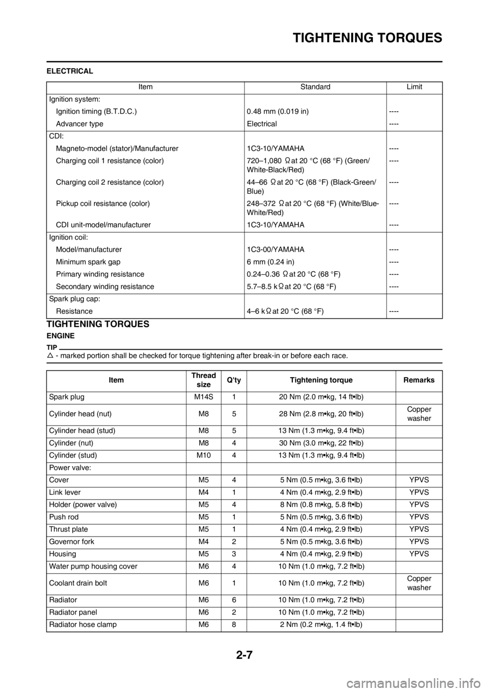
ELECTRICAL
TIGHTENING TORQUES
ENGINE
△- marked portion shall be checked for torque tightening after break-in or before each race.
Item Standard Limit
Ignition system:
Ignition timing (B.T.D.C.) 0.48 mm (0.019 in) ----
Advancer type Electrical ----
CDI:
Magneto-model (stator)/Manufacturer 1C3-10/YAMAHA ----
Charging coil 1 resistance (color) 720–1,080 Ωat 20 °C (68 °F) (Green/
White-Black/Red)----
Charging coil 2 resistance (color) 44–66 Ωat 20 °C (68 °F) (Black-Green/
Blue)----
Pickup coil resistance (color) 248–372 Ωat 20 °C (68 °F) (White/Blue-
White/Red)----
CDI unit-model/manufacturer 1C3-10/YAMAHA ----
Ignition coil:
Model/manufacturer 1C3-00/YAMAHA ----
Minimum spark gap 6 mm (0.24 in) ----
Primary winding resistance 0.24–0.36 Ωat 20 °C (68 °F) ----
Secondary winding resistance 5.7–8.5 kΩat 20 °C (68 °F) ----
Spark plug cap:
Resistance 4–6 kΩat 20 °C (68 °F) ----
ItemThread
sizeQ'ty Tightening torque Remarks
Spark plug M14S 1 20 Nm (2.0 m•kg, 14 ft•lb)
Cylinder head (nut) M8 5 28 Nm (2.8 m•kg, 20 ft•lb)Copper
washer
Cylinder head (stud) M8 5 13 Nm (1.3 m•kg, 9.4 ft•lb)
Cylinder (nut) M8 4 30 Nm (3.0 m•kg, 22 ft•lb)
Cylinder (stud) M10 4 13 Nm (1.3 m•kg, 9.4 ft•lb)
Power valve:
Cover M5 4 5 Nm (0.5 m•kg, 3.6 ft•lb) YPVS
Link lever M4 1 4 Nm (0.4 m•kg, 2.9 ft•lb) YPVS
Holder (power valve) M5 4 8 Nm (0.8 m•kg, 5.8 ft•lb) YPVS
Push rod M5 1 5 Nm (0.5 m•kg, 3.6 ft•lb) YPVS
Thrust plate M5 1 4 Nm (0.4 m•kg, 2.9 ft•lb) YPVS
Governor fork M4 2 5 Nm (0.5 m•kg, 3.6 ft•lb) YPVS
Housing M5 3 4 Nm (0.4 m•kg, 2.9 ft•lb) YPVS
Water pump housing cover M6 4 10 Nm (1.0 m•kg, 7.2 ft•lb)
Coolant drain bolt M6 1 10 Nm (1.0 m•kg, 7.2 ft•lb)Copper
washer
Radiator M6 6 10 Nm (1.0 m•kg, 7.2 ft•lb)
Radiator panel M6 2 10 Nm (1.0 m•kg, 7.2 ft•lb)
Radiator hose clamp M6 8 2 Nm (0.2 m•kg, 1.4 ft•lb)
Page 32 of 168
2-8
TIGHTENING TORQUES
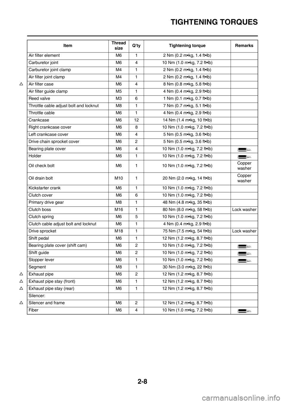
Air filter element M6 1 2 Nm (0.2 m•kg, 1.4 ft•lb)
Carburetor joint M6 4 10 Nm (1.0 m•kg, 7.2 ft•lb)
Carburetor joint clamp M4 1 2 Nm (0.2 m•kg, 1.4 ft•lb)
Air filter joint clamp M4 1 2 Nm (0.2 m•kg, 1.4 ft•lb)
△Air filter case M6 4 8 Nm (0.8 m•kg, 5.8 ft•lb)
Air filter guide clamp M5 1 4 Nm (0.4 m•kg, 2.9 ft•lb)
Reed valve M3 6 1 Nm (0.1 m•kg, 0.7 ft•lb)
Throttle cable adjust bolt and locknut M8 1 7 Nm (0.7 m•kg, 5.1 ft•lb)
Throttle cable M6 1 4 Nm (0.4 m•kg, 2.9 ft•lb)
Crankcase M6 12 14 Nm (1.4 m•kg, 10 ft•lb)
Right crankcase cover M6 8 10 Nm (1.0 m•kg, 7.2 ft•lb)
Left crankcase cover M6 4 5 Nm (0.5 m•kg, 3.6 ft•lb)
Drive chain sprocket cover M6 2 5 Nm (0.5 m•kg, 3.6 ft•lb)
Bearing plate cover M6 4 10 Nm (1.0 m•kg, 7.2 ft•lb)
Holder M6 1 10 Nm (1.0 m•kg, 7.2 ft•lb)
Oil check bolt M6 1 10 Nm (1.0 m•kg, 7.2 ft•lb)Copper
washer
Oil drain bolt M10 1 20 Nm (2.0 m•kg, 14 ft•lb)Copper
washer
Kickstarter crank M6 1 10 Nm (1.0 m•kg, 7.2 ft•lb)
Clutch cover M6 6 10 Nm (1.0 m•kg, 7.2 ft•lb)
Primary drive gear M8 1 48 Nm (4.8 m•kg, 35 ft•lb)
Clutch boss M16 1 80 Nm (8.0 m•kg, 58 ft•lb) Lock washer
Clutch spring M6 5 10 Nm (1.0 m•kg, 7.2 ft•lb)
Clutch cable adjust bolt and locknutM6 1 4 Nm (0.4 m•kg, 2.9 ft•lb)
Drive sprocket M18 1 75 Nm (7.5 m•kg, 54 ft•lb) Lock washer
Shift pedal M6 1 12 Nm (1.2 m•kg, 8.7 ft•lb)
Bearing plate cover (shift cam) M6 2 10 Nm (1.0 m•kg, 7.2 ft•lb)
Shift guide M6 2 10 Nm (1.0 m•kg, 7.2 ft•lb)
Stopper lever M6 1 10 Nm (1.0 m•kg, 7.2 ft•lb)
Segment M8 1 30 Nm (3.0 m•kg, 22 ft•lb)
△Exhaust pipe M6 2 12 Nm (1.2 m•kg, 8.7 ft•lb)
△Exhaust pipe stay (front) M6 1 12 Nm (1.2 m•kg, 8.7 ft•lb)
△Exhaust pipe stay (rear) M6 1 12 Nm (1.2 m•kg, 8.7 ft•lb)
Silencer:
△Silencer and frame M6 2 12 Nm (1.2 m•kg, 8.7 ft•lb)
Fiber M6 4 10 Nm (1.0 m•kg, 7.2 ft•lb)ItemThread
sizeQ'ty Tightening torque Remarks
Page 33 of 168
2-9
TIGHTENING TORQUES
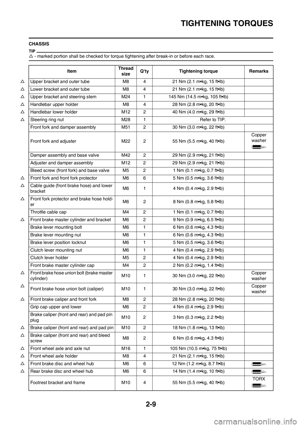
CHASSIS
△- marked portion shall be checked for torque tightening after break-in or before each race.
ItemThread
sizeQ'ty Tightening torque Remarks
△Upper bracket and outer tube M84 21 Nm (2.1 m•kg, 15 ft•lb)
△Lower bracket and outer tube M8 4 21 Nm (2.1 m•kg, 15 ft•lb)
△Upper bracket and steering stem M24 1 145 Nm (14.5 m•kg, 105 ft•lb)
△Handlebar upper holder M8 4 28 Nm (2.8 m•kg, 20 ft•lb)
△Handlebar lower holder M12 2 40 Nm (4.0 m•kg, 29 ft•lb)
△Steering ring nut M28 1 Refer to TIP.
Front fork and damper assembly M51 2 30 Nm (3.0 m•kg, 22 ft•lb)
Front fork and adjuster M22 2 55 Nm (5.5 m•kg, 40 ft•lb)Copper
washer
Damper assembly and base valve M42 2 29 Nm (2.9 m•kg, 21 ft•lb)
Adjuster and damper assembly M12 2 29 Nm (2.9 m•kg, 21 ft•lb)
Bleed screw (front fork) and base valve M5 2 1 Nm (0.1 m•kg, 0.7 ft•lb)
△Front fork and front fork protector M6 6 5 Nm (0.5 m•kg, 3.6 ft•lb)
△Cable guide (front brake hose) and lower
bracketM6 1 4 Nm (0.4 m•kg, 2.9 ft•lb)
△Front fork protector and brake hose hold-
erM6 2 8 Nm (0.8 m•kg, 5.8 ft•lb)
Throttle cable cap M4 2 1 Nm (0.1 m•kg, 0.7 ft•lb)
△Front brake master cylinder and bracket M6 2 9 Nm (0.9 m•kg, 6.5 ft•lb)
Brake lever mounting bolt M6 1 6 Nm (0.6 m•kg, 4.3 ft•lb)
Brake lever mounting nut M6 1 6 Nm (0.6 m•kg, 4.3 ft•lb)
Brake lever position locknut M6 1 5 Nm (0.5 m•kg, 3.6 ft•lb)
Clutch lever mounting nut M6 1 4 Nm (0.4 m•kg, 2.9 ft•lb)
Clutch lever holder M5 2 4 Nm (0.4 m•kg, 2.9 ft•lb)
Front brake master cylinder cap M4 2 2 Nm (0.2 m•kg, 1.4 ft•lb)
△Front brake hose union bolt (brake master
cylinder)M10 1 30 Nm (3.0 m•kg, 22 ft•lb)Copper
washer
△
Front brake hose union bolt (caliper) M10 1 30 Nm (3.0 m•kg, 22 ft•lb)Copper
washer
△Front brake caliper and front fork M8 2 28 Nm (2.8 m•kg, 20 ft•lb)
Grip cap upper and lower M6 2 4 Nm (0.4 m•kg, 2.9 ft•lb)
Brake caliper (front and rear) and pad pin
plugM10 2 3 Nm (0.3 m•kg, 2.2 ft•lb)
△Brake caliper (front and rear) and pad pin M10 2 18 Nm (1.8 m•kg, 13 ft•lb)
△Brake caliper (front and rear) and bleed
screwM8 2 6 Nm (0.6 m•kg, 4.3 ft•lb)
△Front wheel axle and axle nut M16 1 105 Nm (10.5 m•kg, 75 ft•lb)
△Front wheel axle holder M8 4 21 Nm (2.1 m•kg, 15 ft•lb)
△Front brake disc and wheel hub M6 6 12 Nm (1.2 m•kg, 8.7 ft•lb)
△Rear brake disc and wheel hub M6 6 14 Nm (1.4 m•kg, 10 ft•lb)
Footrest bracket and frame M10 4 55 Nm (5.5 m•kg, 40 ft•lb)TORX
Page 34 of 168

2-10
TIGHTENING TORQUES
△Brake pedal mounting M8 1 26 Nm (2.6 m•kg, 19 ft•lb)
△Rear brake master cylinder and frame M6 2 10 Nm (1.0 m•kg, 7.2 ft•lb)
Rear brake master cylinder cap M4 2 2 Nm (0.2 m•kg, 1.4 ft•lb)
△
Rear brake hose union bolt (caliper) M10 1 30 Nm (3.0 m•kg, 22 ft•lb)Copper
washer
△Rear brake hose union bolt (master cylin-
der)M10 1 30 Nm (3.0 m•kg, 22 ft•lb)Copper
washer
△Rear wheel axle and axle nut M20 1 125 Nm (12.5 m•kg, 90 ft•lb)
△Nipple (spoke) — 72 3 Nm (0.3 m•kg, 2.2 ft•lb)
△Driven sprocket and wheel hub M8 6 42 Nm (4.2 m•kg, 30 ft•lb)
△Disc cover and rear brake caliper M6 2 10 Nm (1.0 m•kg, 7.2 ft•lb)
△Protector and rear brake caliper M6 2 7 Nm (0.7 m•kg, 5.1 ft•lb)
Drive chain puller adjust bolt and locknut M8 2 19 Nm (1.9 m•kg, 13 ft•lb)
Engine :
△Engine and frame (front) M10 1 64 Nm (6.4 m•kg, 46 ft•lb)
△Engine and frame (lower) M10 1 64 Nm (6.4 m•kg, 46 ft•lb)
△Engine bracket and frame M8 2 34 Nm (3.4 m•kg, 24 ft•lb)
△Engine bracket and engine M8 1 34 Nm (3.4 m•kg, 24 ft•lb)
△Pivot shaft and nut M16 1 85 Nm (8.5 m•kg, 61 ft•lb)
△Relay arm and swingarm M14 1 70 Nm (7.0 m•kg, 50 ft•lb)
△Relay arm and connecting rod M14 1 80 Nm (8.0 m•kg, 58 ft•lb)
△Connecting rod and frame M14 1 80 Nm (8.0 m•kg, 58 ft•lb)
△Rear shock absorber and frame M10 1 56 Nm (5.6 m•kg, 40 ft•lb)
△Rear shock absorber and relay arm M10 1 53 Nm (5.3 m•kg, 38 ft•lb)
△Rear frame and frame (upper) M8 1 32 Nm (3.2 m•kg, 23 ft•lb)
△Rear frame and frame (lower) M8 2 29 Nm (2.9 m•kg, 21 ft•lb)
△Swingarm and brake hose holder M54 3 Nm (0.3 m•kg, 2.2 ft•lb)
Swingarm and patch M4 4 2 Nm (0.2 m•kg, 1.4 ft•lb)
Drive chain tensioner M8 2 16 Nm (1.6 m•kg, 11 ft•lb)
Drive chain support and swingarm M6 37 Nm (0.7 m•kg, 5.1 ft•lb)
Seal guard and swingarm M5 4 6 Nm (0.6 m•kg, 4.3 ft•lb)
Cable guide and frame M5 2 4 Nm (0.4 m•kg, 2.9 ft•lb)
△Fuel tank boss and frame M10 2 20 Nm (2.0 m•kg, 14 ft•lb)
△Fuel tank M6 2 10 Nm (1.0 m•kg, 7.2 ft•lb)
△Fuel tank and fuel cock M6 2 4 Nm (0.4 m•kg, 2.9 ft•lb)
Fuel tank and seat set bracket M6 1 7 Nm (0.7 m•kg, 5.1 ft•lb)
Fuel tank and hooking screw (fitting band) M6 1 7 Nm (0.7 m•kg, 5.1 ft•lb)
Fuel tank and fuel tank bracket M6 4 7 Nm (0.7 m•kg, 5.1 ft•lb)
△Air scoop and fuel tank M6 4 7 Nm (0.7 m•kg, 5.1 ft•lb)
△Air scoop and radiator guard (lower) M6 2 6 Nm (0.6 m•kg, 4.3 ft•lb)
△Front fender M6 4 7 Nm (0.7 m•kg, 5.1 ft•lb)
△Rear fender (front) M6 2 7 Nm (0.7 m•kg, 5.1 ft•lb)
△Rear fender (rear) M6 2 12 Nm (1.2 m•kg, 8.7 ft•lb)
△Side cover M6 2 7 Nm (0.7 m•kg, 5.1 ft•lb)
Seat M8 2 19 Nm (1.9 m•kg, 13 ft•lb)ItemThread
sizeQ'ty Tightening torque Remarks
Page 35 of 168

2-11
TIGHTENING TORQUES
1. First, tighten the steering ring nut approximately 38 Nm (3.8 m•kg, 27 ft•lb) by using the steering nut wrench, then loosen
the steering ring nut one turn.
2. Retighten the steering ring nut 7 Nm (0.7 m•kg, 5.1 ft•lb).
ELECTRICAL △Number plate M6 1 7 Nm (0.7 m•kg, 5.1 ft•lb)ItemThread
sizeQ'ty Tightening torque Remarks
ItemThread
sizeQ'ty Tightening torque Remarks
Stator M6 3 7 Nm (0.7 m•kg, 5.1 ft•lb)
Rotor M12 1 56 Nm (5.6 m•kg, 40 ft•lb)
Ignition coil M6 2 7 Nm (0.7 m•kg, 5.1 ft•lb)
Page 36 of 168
2-12
TIGHTENING TORQUES
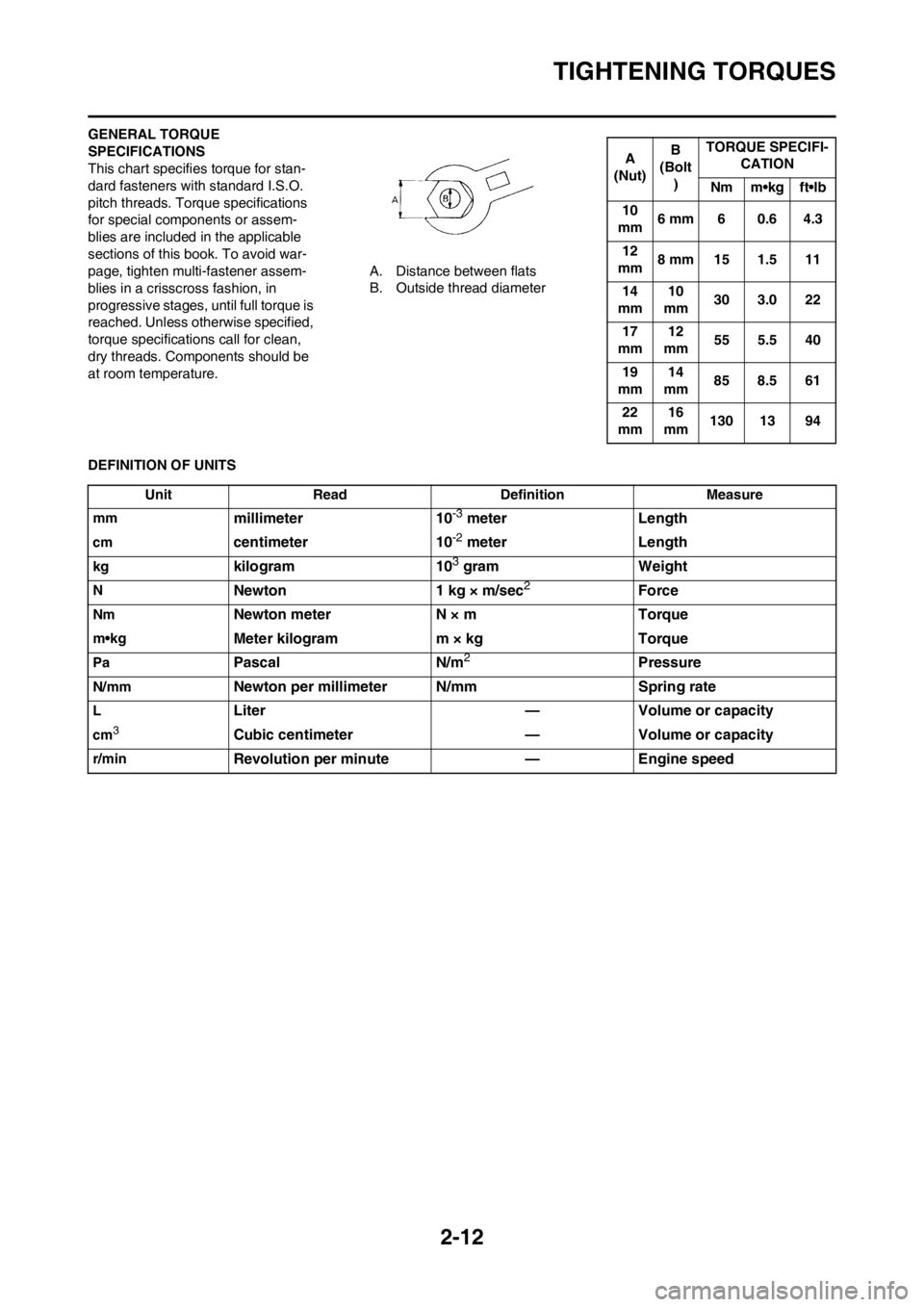
GENERAL TORQUE
SPECIFICATIONS
This chart specifies torque for stan-
dard fasteners with standard I.S.O.
pitch threads. Torque specifications
for special components or assem-
blies are included in the applicable
sections of this book. To avoid war-
page, tighten multi-fastener assem-
blies in a crisscross fashion, in
progressive stages, until full torque is
reached. Unless otherwise specified,
torque specifications call for clean,
dry threads. Components should be
at room temperature.A. Distance between flats
B. Outside thread diameter
DEFINITION OF UNITS
A
(Nut)B
(Bolt
)TORQUE SPECIFI-
CATION
Nm m•kg ft•lb
10
mm6 mm 6 0.6 4.3
12
mm8 mm 15 1.5 11
14
mm10
mm30 3.0 22
17
mm12
mm55 5.5 40
19
mm14
mm85 8.5 61
22
mm16
mm130 13 94
Unit Read Definition Measure
mm
millimeter 10-3 meter Length
cmcentimeter 10-2 meter Length
kgkilogram 103 gram Weight
NNewton 1 kg × m/sec2Force
NmNewton meter N × m Torque
m•kgMeter kilogram m × kg Torque
PaPascal N/m2Pressure
N/mmNewton per millimeter N/mm Spring rate
LLiter — Volume or capacity
cm3Cubic centimeter — Volume or capacity
r/minRevolution per minute — Engine speed
Page 37 of 168

Page 38 of 168
2-13
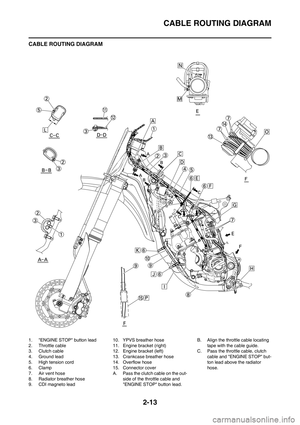
CABLE ROUTING DIAGRAM
CABLE ROUTING DIAGRAM
1. "ENGINE STOP" button lead
2. Throttle cable
3. Clutch cable
4. Ground lead
5. High tension cord
6. Clamp
7. Air vent hose
8. Radiator breather hose
9. CDI magneto lead10. YPVS breather hose
11. Engine bracket (right)
12. Engine bracket (left)
13. Crankcase breather hose
14. Overflow hose
15. Connector cover
A. Pass the clutch cable on the out-
side of the throttle cable and
"ENGINE STOP" button lead.B. Align the throttle cable locating
tape with the cable guide.
C. Pass the throttle cable, clutch
cable and "ENGINE STOP" but-
ton lead above the radiator
hose.
Page 39 of 168

2-14
CABLE ROUTING DIAGRAM
D. Install the ignition coil, side core
and ground lead together to the
frame. Take care to fasten the
ground lead so that its terminal
is within the indicated range.
E. Clamp the throttle cable and
high tension cord to the frame.
F. Clamp the clutch cable to the left
engine bracket. Clamp the
clutch cable below the position-
ing grommet.
G. Pass the air vent hose back of
the throttle cable.
H. Pass the air vent hose, overflow
hose and crankcase breather
hose between the frame and
connecting rod.
I. Pass the radiator breather hose
and YPVS breather hose out-
side the engine bracket and in-
side the down tube. Then pass
the radiator breather hose inside
the YPVS breather hose.
J. Clamp the CDI magneto lead,
radiator breather hose and
YPVS breather hose to the
frame.
K. Clamp to the frame the CDI
magneto lead and radiator
breather hose. Take care to
clamp them above the projection
on the frame.
L. Locate the clamp ends in the ar-
rowed range.
M. Direct the clip with its finger grip
facing forward.
N. Tighten the clamp with its bolt
head facing the left side of the
chassis (on both sides of the
carburetor joint and the air filter
joint).
O. Pass the air vent hose, overflow
hose and crankcase breather
hose so that they do not contact
the rear shock absorber.
P. Bring the connector cover into
contact with the coupler.
Page 40 of 168
2-15
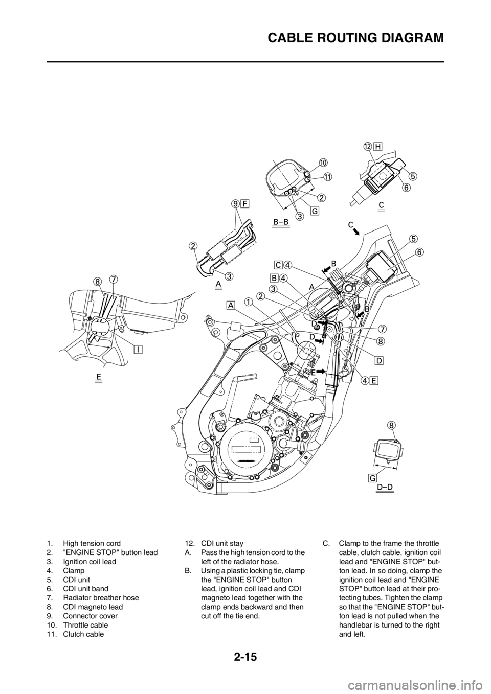
CABLE ROUTING DIAGRAM
1. High tension cord
2. "ENGINE STOP" button lead
3. Ignition coil lead
4. Clamp
5. CDI unit
6. CDI unit band
7. Radiator breather hose
8. CDI magneto lead
9. Connector cover
10. Throttle cable
11. Clutch cable12. CDI unit stay
A. Pass the high tension cord to the
left of the radiator hose.
B. Using a plastic locking tie, clamp
the "ENGINE STOP" button
lead, ignition coil lead and CDI
magneto lead together with the
clamp ends backward and then
cut off the tie end.C. Clamp to the frame the throttle
cable, clutch cable, ignition coil
lead and "ENGINE STOP" but-
ton lead. In so doing, clamp the
ignition coil lead and "ENGINE
STOP" button lead at their pro-
tecting tubes. Tighten the clamp
so that the "ENGINE STOP" but-
ton lead is not pulled when the
handlebar is turned to the right
and left.