YAMAHA YZ125LC 2012 Repair Manual
Manufacturer: YAMAHA, Model Year: 2012, Model line: YZ125LC, Model: YAMAHA YZ125LC 2012Pages: 168, PDF Size: 8.27 MB
Page 61 of 168
3-18
CHASSIS
LUBRICATION
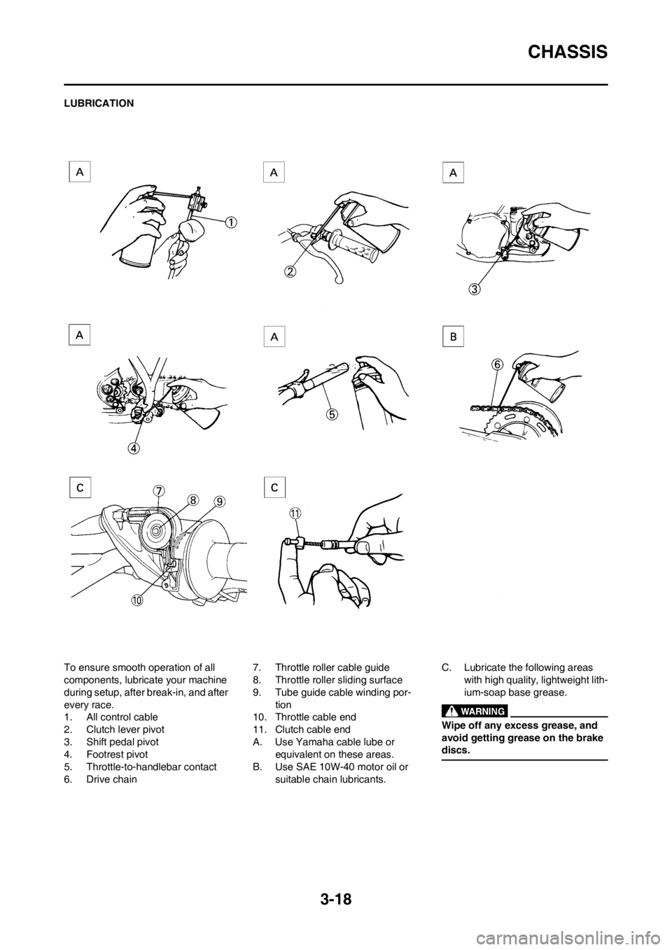
To ensure smooth operation of all
components, lubricate your machine
during setup, after break-in, and after
every race.
1. All control cable
2. Clutch lever pivot
3. Shift pedal pivot
4. Footrest pivot
5. Throttle-to-handlebar contact
6. Drive chain7. Throttle roller cable guide
8. Throttle roller sliding surface
9. Tube guide cable winding por-
tion
10. Throttle cable end
11. Clutch cable end
A. Use Yamaha cable lube or
equivalent on these areas.
B. Use SAE 10W-40 motor oil or
suitable chain lubricants.C. Lubricate the following areas
with high quality, lightweight lith-
ium-soap base grease.
Wipe off any excess grease, and
avoid getting grease on the brake
discs.
Page 62 of 168
3-19
ELECTRICAL
ELECTRICAL
CHECKING THE SPARK PLUG
1. Remove:
• Spark plug
2. Inspect:
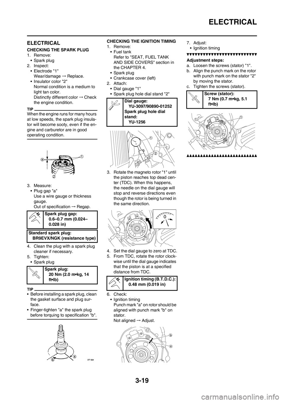
• Electrode "1"
Wear/damage→Replace.
• Insulator color "2"
Normal condition is a medium to
light tan color.
Distinctly different color→Check
the engine condition.
When the engine runs for many hours
at low speeds, the spark plug insula-
tor will become sooty, even if the en-
gine and carburetor are in good
operating condition.
3. Measure:
• Plug gap "a"
Use a wire gauge or thickness
gauge.
Out of specification→Regap.
4. Clean the plug with a spark plug
cleaner if necessary.
5. Tighten:
• Spark plug
• Before installing a spark plug, clean
the gasket surface and plug sur-
face.
• Finger-tighten "a" the spark plug
before torquing to specification "b".
CHECKING THE IGNITION TIMING
1. Remove:
•Fuel tank
Refer to "SEAT, FUEL TANK
AND SIDE COVERS" section in
the CHAPTER 4.
• Spark plug
• Crankcase cover (left)
2. Attach:
• Dial gauge "1"
• Spark plug hole dial stand "2"
3. Rotate the magneto rotor "1" until
the piston reaches top dead cen-
ter (TDC). When this happens,
the needle on the dial gauge will
stop and reverse directions even
though the rotor is being turned in
the same direction.
4. Set the dial gauge to zero at TDC.
5. From TDC, rotate the rotor clock-
wise until the dial gauge indicates
that the piston is at a specified
distance from TDC.
6. Check:
• Ignition timing
Punch mark "a" on rotor should be
aligned with punch mark "b" on
stator.
Not aligned→Adjust.7. Adjust:
• Ignition timing
Adjustment steps:
a. Loosen the screws (stator) "1".
b. Align the punch mark on the rotor
with punch mark on the stator "2"
by moving the stator.
c. Tighten the screws (stator).
Spark plug gap:
0.6–0.7 mm (0.024–
0.028 in)
Standard spark plug:
BR9EVX/NGK (resistance type)
Spark plug:
20 Nm (2.0 m•kg, 14
ft•lb)
Dial gauge:
YU-3097/90890-01252
Spark plug hole dial
stand:
YU-1256
Ignition timing (B.T.D.C.):
0.48 mm (0.019 in)
Screw (stator):
7 Nm (0.7 m•kg, 5.1
ft•lb)
Page 63 of 168
4-1
SEAT, FUEL TANK AND SIDE COVERS
ENGINE
This section is intended for those who have basic knowledge and skill concerning the servicing of Yamaha motorcycles
(e.g., Yamaha dealers, service engineers, etc.) Those who have little knowledge and skill concerning servicing are request-
ed not to undertake inspection, adjustment, disassembly, or reassembly only by reference to this manual. It may lead to
servicing trouble and mechanical damage.
SEAT, FUEL TANK AND SIDE COVERS
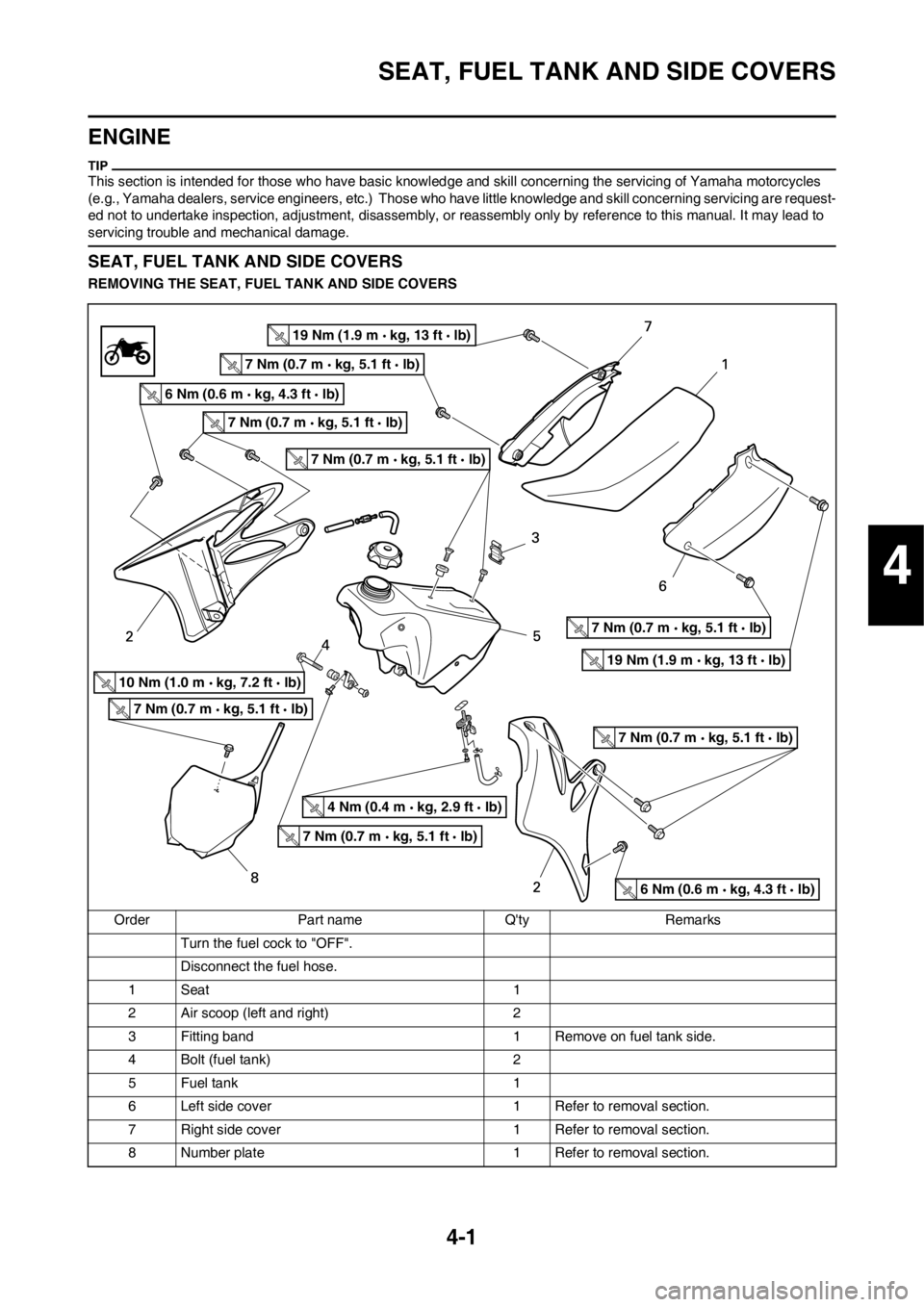
REMOVING THE SEAT, FUEL TANK AND SIDE COVERS
Order Part name Q'ty Remarks
Turn the fuel cock to "OFF".
Disconnect the fuel hose.
1Seat 1
2 Air scoop (left and right) 2
3 Fitting band 1 Remove on fuel tank side.
4 Bolt (fuel tank) 2
5 Fuel tank 1
6 Left side cover 1 Refer to removal section.
7 Right side cover 1 Refer to removal section.
8 Number plate 1 Refer to removal section.
19 Nm (1.9 m kg, 13 ft lb)
7 Nm (0.7 m kg, 5.1 ft lb)
7 Nm (0.7 m kg, 5.1 ft lb)
7 Nm (0.7 m kg, 5.1 ft lb)
7 Nm (0.7 m kg, 5.1 ft lb)
7 Nm (0.7 m kg, 5.1 ft lb)
7 Nm (0.7 m kg, 5.1 ft lb)
7 Nm (0.7 m kg, 5.1 ft lb)
19 Nm (1.9 m kg, 13 ft lb)
6 Nm (0.6 m kg, 4.3 ft lb)
6 Nm (0.6 m kg, 4.3 ft lb)
10 Nm (1.0 m kg, 7.2 ft lb)
4 Nm (0.4 m kg, 2.9 ft lb)
4
Page 64 of 168
4-2
SEAT, FUEL TANK AND SIDE COVERS
REMOVING THE SIDE COVER
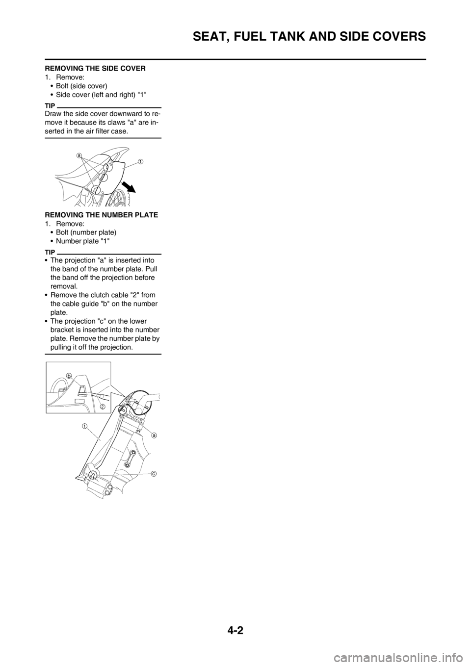
1. Remove:
• Bolt (side cover)
• Side cover (left and right) "1"
Draw the side cover downward to re-
move it because its claws "a" are in-
serted in the air filter case.
REMOVING THE NUMBER PLATE
1. Remove:
• Bolt (number plate)
• Number plate "1"
• The projection "a" is inserted into
the band of the number plate. Pull
the band off the projection before
removal.
• Remove the clutch cable "2" from
the cable guide "b" on the number
plate.
• The projection "c" on the lower
bracket is inserted into the number
plate. Remove the number plate by
pulling it off the projection.
Page 65 of 168
4-3
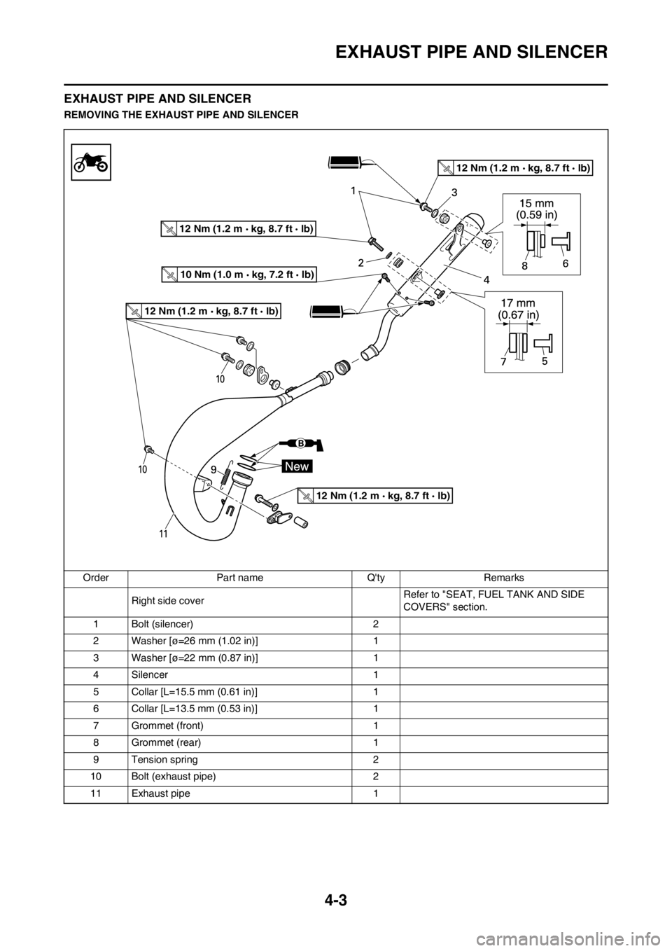
EXHAUST PIPE AND SILENCER
EXHAUST PIPE AND SILENCER
REMOVING THE EXHAUST PIPE AND SILENCER
Order Part name Q'ty Remarks
Right side coverRefer to "SEAT, FUEL TANK AND SIDE
COVERS" section.
1 Bolt (silencer) 2
2 Washer [ø=26 mm (1.02 in)] 1
3 Washer [ø=22 mm (0.87 in)] 1
4 Silencer 1
5 Collar [L=15.5 mm (0.61 in)] 1
6 Collar [L=13.5 mm (0.53 in)] 1
7 Grommet (front) 1
8 Grommet (rear) 1
9 Tension spring 2
10 Bolt (exhaust pipe) 2
11 Exhaust pipe 1
10 Nm (1.0 m kg, 7.2 ft lb)
12 Nm (1.2 m kg, 8.7 ft lb)
12 Nm (1.2 m kg, 8.7 ft lb)
12 Nm (1.2 m kg, 8.7 ft lb)
12 Nm (1.2 m kg, 8.7 ft lb)
Page 66 of 168
4-4
EXHAUST PIPE AND SILENCER
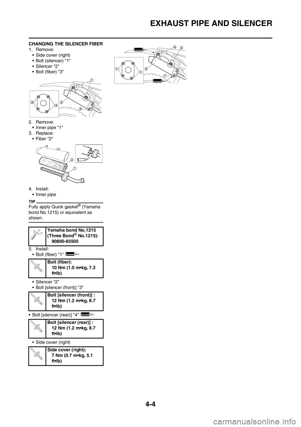
CHANGING THE SILENCER FIBER
1. Remove:
• Side cover (right)
• Bolt (silencer) "1"
• Silencer "2"
• Bolt (fiber) "3"
2. Remove:
• Inner pipe "1"
3. Replace:
• Fiber "2"
4. Install:
• Inner pipe
Fully apply Quick gasket® (Yamaha
bond No.1215) or equivalent as
shown.
5. Install:
• Bolt (fiber) "1"
• Silencer "2"
• Bolt [silencer (front)] "3"
• Bolt [silencer (rear)] "4"
• Side cover (right)Yamaha bond No.1215
(Three Bond
® No.1215):
90890-85505
Bolt (fiber):
10 Nm (1.0 m•kg, 7.2
ft•lb)
Bolt [silencer (front)] :
12 Nm (1.2 m•kg, 8.7
ft•lb)
Bolt [silencer (rear)] :
12 Nm (1.2 m•kg, 8.7
ft•lb)
Side cover (right):
7 Nm (0.7 m•kg, 5.1
ft•lb)
Page 67 of 168
4-5
RADIATOR
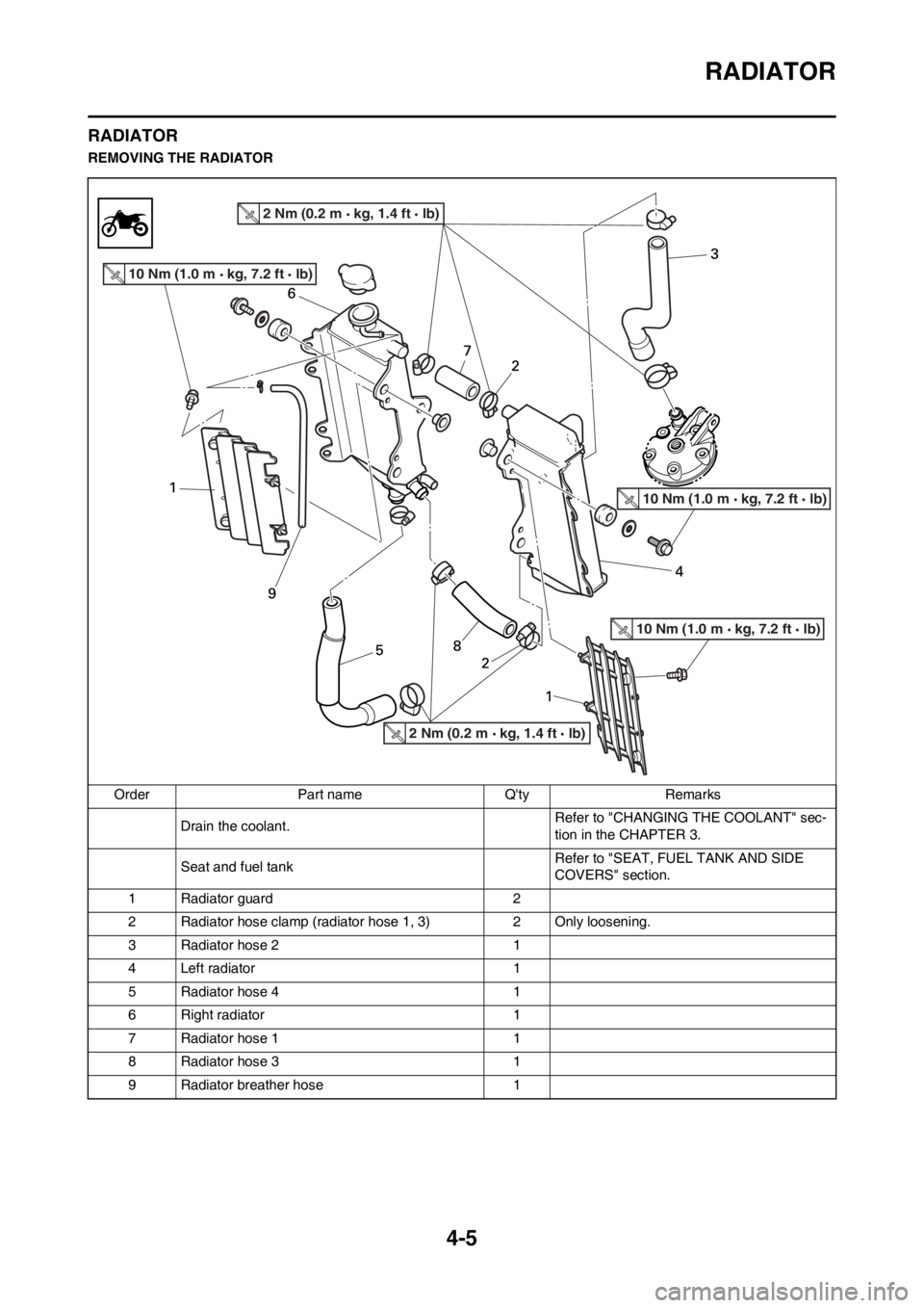
RADIATOR
REMOVING THE RADIATOR
Order Part name Q'ty Remarks
Drain the coolant.Refer to "CHANGING THE COOLANT" sec-
tion in the CHAPTER 3.
Seat and fuel tankRefer to "SEAT, FUEL TANK AND SIDE
COVERS" section.
1 Radiator guard 2
2 Radiator hose clamp (radiator hose 1, 3) 2 Only loosening.
3 Radiator hose 2 1
4 Left radiator 1
5 Radiator hose 4 1
6 Right radiator 1
7 Radiator hose 1 1
8 Radiator hose 3 1
9 Radiator breather hose 1
10 Nm (1.0 m kg, 7.2 ft lb)
2 Nm (0.2 m kg, 1.4 ft lb)
10 Nm (1.0 m kg, 7.2 ft lb)
10 Nm (1.0 m kg, 7.2 ft lb)
2 Nm (0.2 m kg, 1.4 ft lb)
Page 68 of 168
4-6
RADIATOR
HANDLING NOTE
Do not remove the radiator cap
when the engine and radiator are
hot. Scalding hot fluid and steam
may be blown out under pressure,
which could cause serious injury.
When the engine has cooled, open
the radiator cap by the following
procedure:
Place a thick rag, like a towel, over
the radiator cap, slowly rotate the
cap counterclockwise to the de-
tent. This procedure allows any re-
sidual pressure to escape. When
the hissing sound has stopped,
press down on the cap while turn-
ing counterclockwise and remove
it.
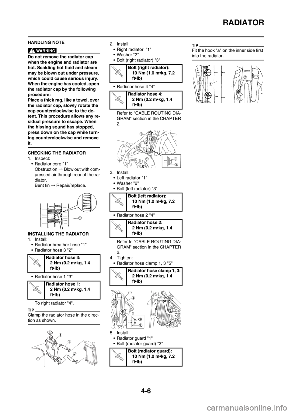
CHECKING THE RADIATOR
1. Inspect:
• Radiator core "1"
Obstruction→Blow out with com-
pressed air through rear of the ra-
diator.
Bent fin→Repair/replace.
INSTALLING THE RADIATOR
1. Install:
• Radiator breather hose "1"
• Radiator hose 3 "2"
• Radiator hose 1 "3"
To right radiator "4".
Clamp the radiator hose in the direc-
tion as shown.
2. Install:
• Right radiator "1"
• Washer "2"
• Bolt (right radiator) "3"
• Radiator hose 4 "4"
Refer to "CABLE ROUTING DIA-
GRAM" section in the CHAPTER
2.
3. Install:
• Left radiator "1"
• Washer "2"
• Bolt (left radiator) "3"
• Radiator hose 2 "4"
Refer to "CABLE ROUTING DIA-
GRAM" section in the CHAPTER
2.
4. Tighten:
• Radiator hose clamp 1, 3 "5"
5. Install:
• Radiator guard "1"
• Bolt (radiator guard) "2"
Fit the hook "a" on the inner side first
into the radiator.
Radiator hose 3:
2 Nm (0.2 m•kg, 1.4
ft•lb)
Radiator hose 1:
2 Nm (0.2 m•kg, 1.4
ft•lb)
Bolt (right radiator):
10 Nm (1.0 m•kg, 7.2
ft•lb)
Radiator hose 4:
2 Nm (0.2 m•kg, 1.4
ft•lb)
Bolt (left radiator):
10 Nm (1.0 m•kg, 7.2
ft•lb)
Radiator hose 2:
2 Nm (0.2 m•kg, 1.4
ft•lb)
Radiator hose clamp 1, 3:
2 Nm (0.2 m•kg, 1.4
ft•lb)
Bolt (radiator guard):
10 Nm (1.0 m•kg, 7.2
ft•lb)
Page 69 of 168
4-7
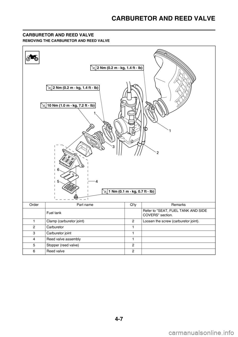
CARBURETOR AND REED VALVE
CARBURETOR AND REED VALVE
REMOVING THE CARBURETOR AND REED VALVE
Order Part name Q'ty Remarks
Fuel tank Refer to "SEAT, FUEL TANK AND SIDE
COVERS" section.
1 Clamp (carburetor joint) 2 Loosen the screw (carburetor joint).
2 Carburetor 1
3 Carburetor joint 1
4 Reed valve assembly 1
5 Stopper (reed valve) 2
6 Reed valve 2
10 Nm (1.0 m kg, 7.2 ft lb)
2 Nm (0.2 m kg, 1.4 ft lb)
2 Nm (0.2 m kg, 1.4 ft lb)
1 Nm (0.1 m kg, 0.7 ft lb)
Page 70 of 168
4-8
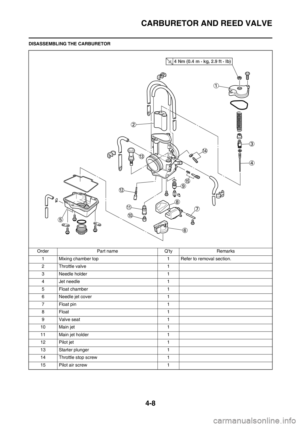
CARBURETOR AND REED VALVE
DISASSEMBLING THE CARBURETOR
Order Part name Q'ty Remarks
1 Mixing chamber top 1 Refer to removal section.
2 Throttle valve 1
3 Needle holder 1
4 Jet needle 1
5 Float chamber 1
6 Needle jet cover 1
7 Float pin 1
8 Float 1
9 Valve seat 1
10 Main jet 1
11 Main jet holder 1
12 Pilot jet 1
13 Starter plunger 1
14 Throttle stop screw 1
15 Pilot air screw 1
4 Nm (0.4 m kg, 2.9 ft lb)