YAMAHA YZ250F 2006 Manuale duso (in Italian)
Manufacturer: YAMAHA, Model Year: 2006, Model line: YZ250F, Model: YAMAHA YZ250F 2006Pages: 674, PDF Dimensioni: 21.07 MB
Page 541 of 674
5 - 41
CHAS
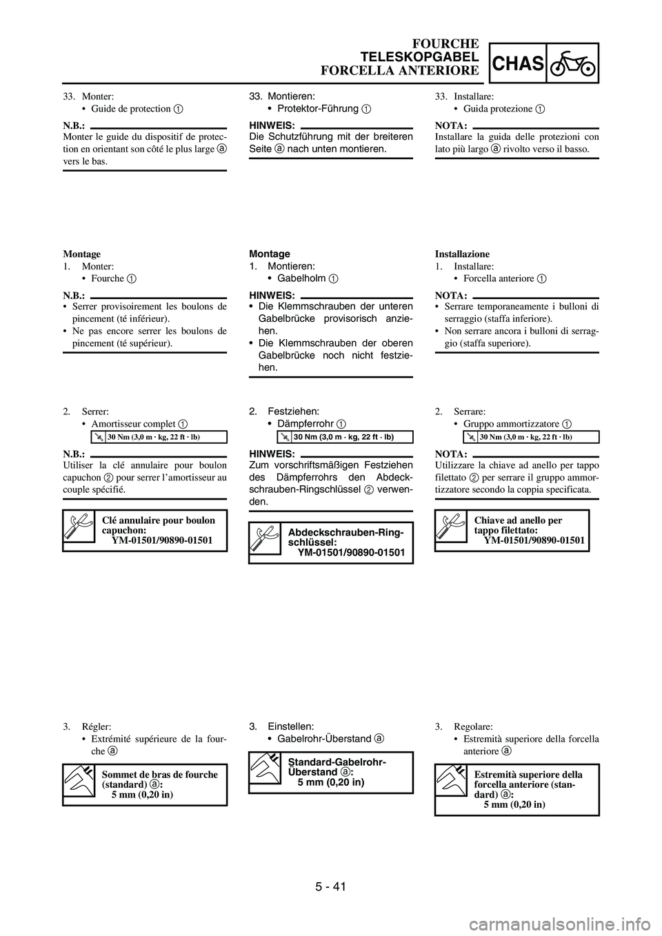
33. Montieren:
Protektor-Führung
1
HINWEIS:
Die Schutzführung mit der breiteren
Seite
a nach unten montieren.
Montage
1. Montieren:
Gabelholm
1
HINWEIS:
Die Klemmschrauben der unteren
Gabelbrücke provisorisch anzie-
hen.
Die Klemmschrauben der oberen
Gabelbrücke noch nicht festzie-
hen.
2. Festziehen:
Dämpferrohr
1
HINWEIS:
Zum vorschriftsmäßigen Festziehen
des Dämpferrohrs den Abdeck-
schrauben-Ringschlüssel
2 verwen-
den.
T R..30 Nm (3,0 m · kg, 22 ft · lb)
Abdeckschrauben-Ring-
schlüssel:
YM-01501/90890-01501
3. Einstellen:
Gabelrohr-Überstand
a
Standard-Gabelrohr-
Überstand a:
5 mm (0,20 in)
33. Monter:
Guide de protection 1
N.B.:
Monter le guide du dispositif de protec-
tion en orientant son côté le plus large a
vers le bas.
Montage
1. Monter:
Fourche 1
N.B.:
Serrer provisoirement les boulons de
pincement (té inférieur).
Ne pas encore serrer les boulons de
pincement (té supérieur).
2. Serrer:
Amortisseur complet 1
N.B.:
Utiliser la clé annulaire pour boulon
capuchon 2 pour serrer l’amortisseur au
couple spécifié.
T R..30 Nm (3,0 m · kg, 22 ft · lb)
Clé annulaire pour boulon
capuchon:
YM-01501/90890-01501
3. Régler:
Extrémité supérieure de la four-
che a
Sommet de bras de fourche
(standard) a:
5 mm (0,20 in)
33. Installare:
Guida protezione 1
NOTA:
Installare la guida delle protezioni con
lato più largo a rivolto verso il basso.
Installazione
1. Installare:
Forcella anteriore 1
NOTA:
Serrare temporaneamente i bulloni di
serraggio (staffa inferiore).
Non serrare ancora i bulloni di serrag-
gio (staffa superiore).
2. Serrare:
Gruppo ammortizzatore 1
NOTA:
Utilizzare la chiave ad anello per tappo
filettato 2 per serrare il gruppo ammor-
tizzatore secondo la coppia specificata.
T R..30 Nm (3,0 m · kg, 22 ft · lb)
Chiave ad anello per
tappo filettato:
YM-01501/90890-01501
3. Regolare:
Estremità superiore della forcella
anteriore a
Estremità superiore della
forcella anteriore (stan-
dard) a:
5 mm (0,20 in)
FOURCHE
TELESKOPGABEL
FORCELLA ANTERIORE
Page 542 of 674
5 - 42
CHAS
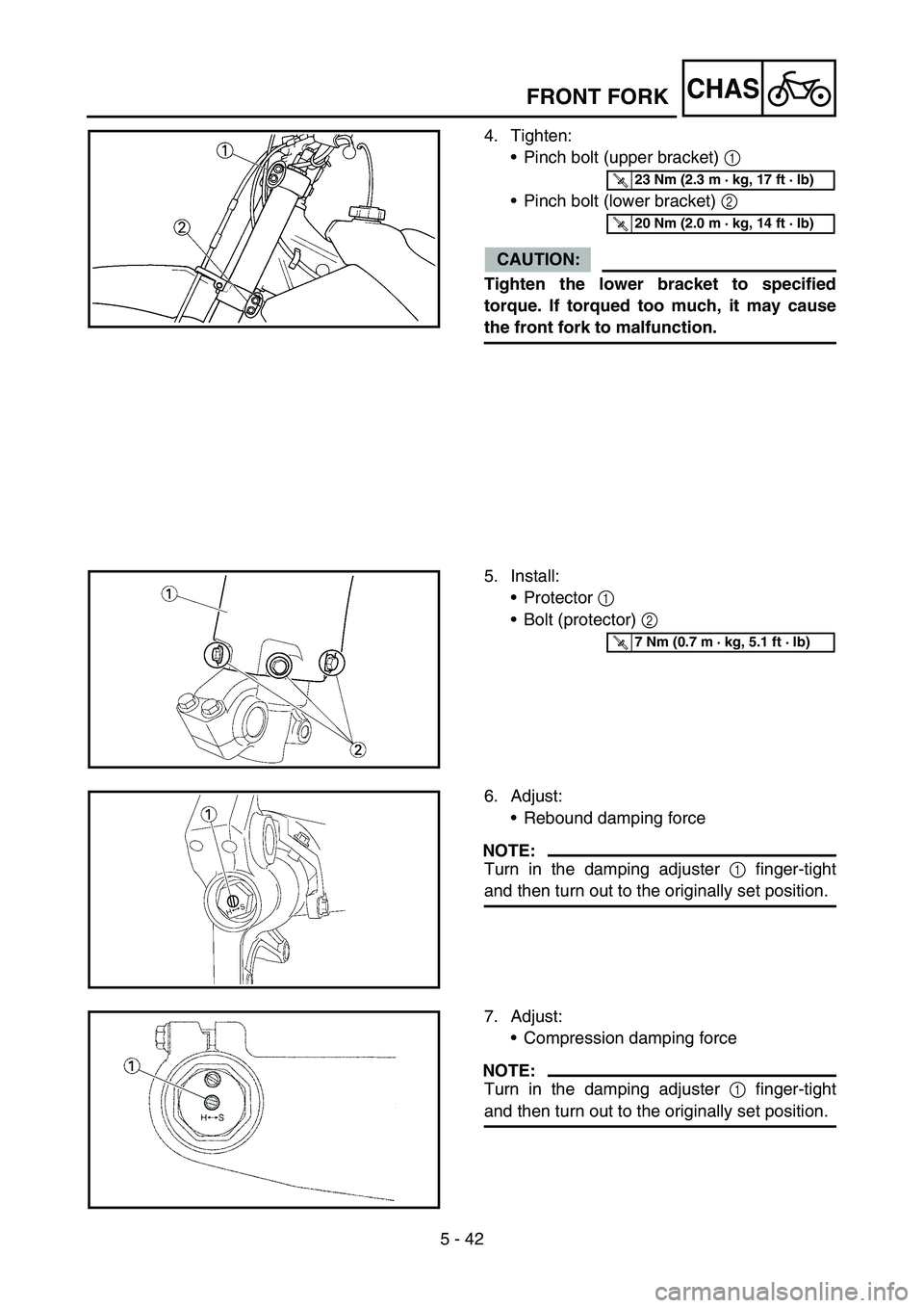
4. Tighten:
Pinch bolt (upper bracket) 1
Pinch bolt (lower bracket) 2
CAUTION:
Tighten the lower bracket to specified
torque. If torqued too much, it may cause
the front fork to malfunction.
T R..23 Nm (2.3 m · kg, 17 ft · lb)
T R..20 Nm (2.0 m · kg, 14 ft · lb)
5. Install:
Protector 1
Bolt (protector) 2
T R..7 Nm (0.7 m · kg, 5.1 ft · lb)
6. Adjust:
Rebound damping force
NOTE:
Turn in the damping adjuster 1 finger-tight
and then turn out to the originally set position.
7. Adjust:
Compression damping force
NOTE:
Turn in the damping adjuster 1 finger-tight
and then turn out to the originally set position.
FRONT FORK
Page 543 of 674
5 - 42
CHAS
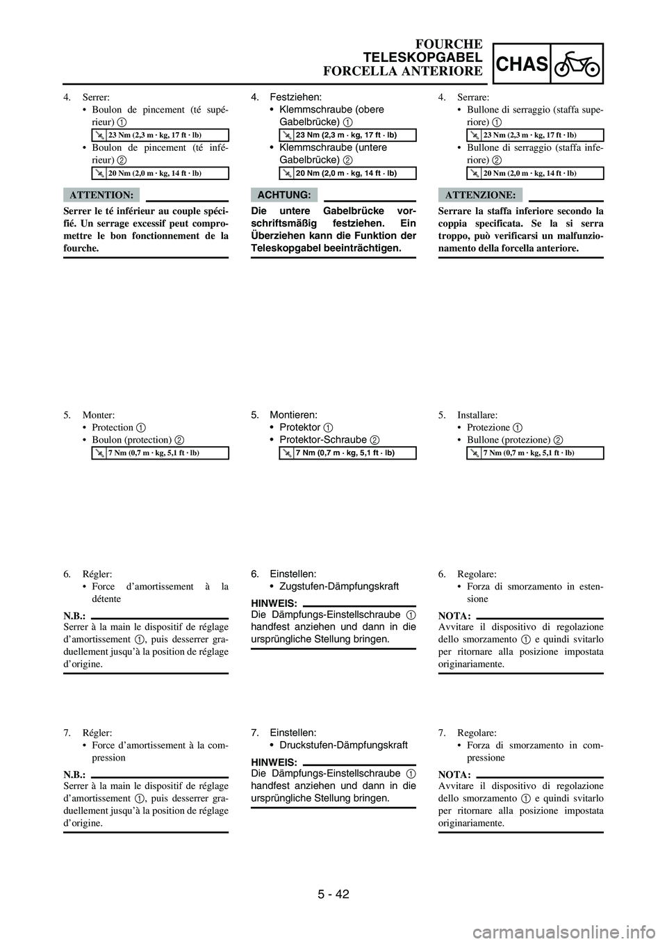
4. Festziehen:
Klemmschraube (obere
Gabelbrücke)
1
Klemmschraube (untere
Gabelbrücke)
2
ACHTUNG:
Die untere Gabelbrücke vor-
schriftsmäßig festziehen. Ein
Überziehen kann die Funktion der
Teleskopgabel beeinträchtigen.
T R..23 Nm (2,3 m · kg, 17 ft · lb)
T R..20 Nm (2,0 m · kg, 14 ft · lb)
5. Montieren:
Protektor
1
Protektor-Schraube
2
T R..7 Nm (0,7 m · kg, 5,1 ft · lb)
6. Einstellen:
Zugstufen-Dämpfungskraft
HINWEIS:
Die Dämpfungs-Einstellschraube
1
handfest anziehen und dann in die
ursprüngliche Stellung bringen.
7. Einstellen:
Druckstufen-Dämpfungskraft
HINWEIS:
Die Dämpfungs-Einstellschraube
1
handfest anziehen und dann in die
ursprüngliche Stellung bringen. 4. Serrer:
Boulon de pincement (té supé-
rieur) 1
Boulon de pincement (té infé-
rieur) 2
ATTENTION:
Serrer le té inférieur au couple spéci-
fié. Un serrage excessif peut compro-
mettre le bon fonctionnement de la
fourche.
T R..23 Nm (2,3 m · kg, 17 ft · lb)
T R..20 Nm (2,0 m · kg, 14 ft · lb)
5. Monter:
Protection 1
Boulon (protection) 2
T R..7 Nm (0,7 m · kg, 5,1 ft · lb)
6. Régler:
Force d’amortissement à la
détente
N.B.:
Serrer à la main le dispositif de réglage
d’amortissement 1, puis desserrer gra-
duellement jusqu’à la position de réglage
d’origine.
7. Régler:
Force d’amortissement à la com-
pression
N.B.:
Serrer à la main le dispositif de réglage
d’amortissement 1, puis desserrer gra-
duellement jusqu’à la position de réglage
d’origine.4. Serrare:
Bullone di serraggio (staffa supe-
riore) 1
Bullone di serraggio (staffa infe-
riore) 2
ATTENZIONE:
Serrare la staffa inferiore secondo la
coppia specificata. Se la si serra
troppo, può verificarsi un malfunzio-
namento della forcella anteriore.
T R..23 Nm (2,3 m · kg, 17 ft · lb)
T R..+20 Nm (2,0 m · kg, 14 ft · lb)
5. Installare:
Protezione 1
Bullone (protezione) 2
T R..7 Nm (0,7 m · kg, 5,1 ft · lb)
6. Regolare:
Forza di smorzamento in esten-
sione
NOTA:
Avvitare il dispositivo di regolazione
dello smorzamento 1 e quindi svitarlo
per ritornare alla posizione impostata
originariamente.
7. Regolare:
Forza di smorzamento in com-
pressione
NOTA:
Avvitare il dispositivo di regolazione
dello smorzamento 1 e quindi svitarlo
per ritornare alla posizione impostata
originariamente.
FOURCHE
TELESKOPGABEL
FORCELLA ANTERIORE
Page 544 of 674
5 - 43
CHASHANDLEBAR
EC5B0000
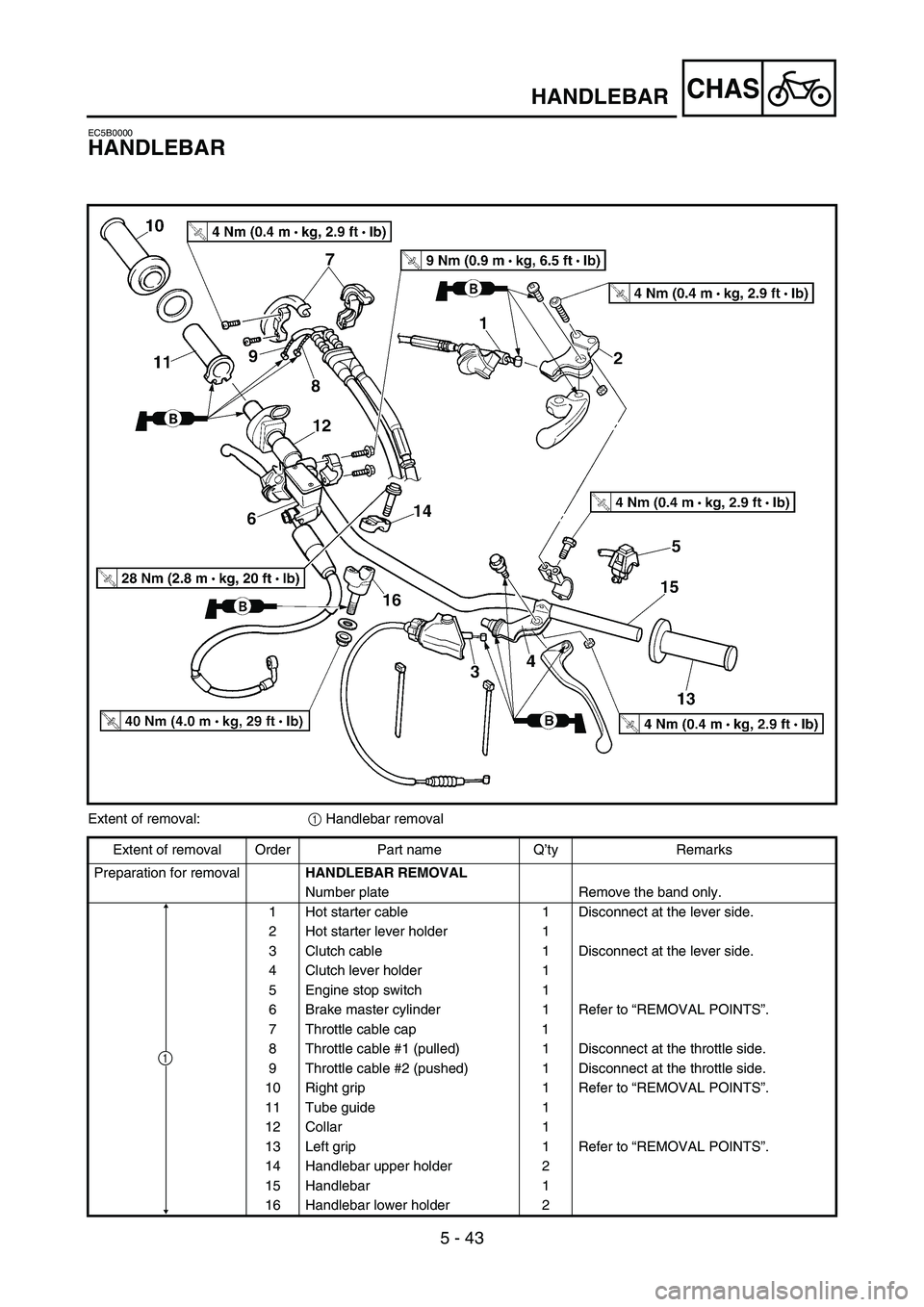
HANDLEBAR
Extent of removal:
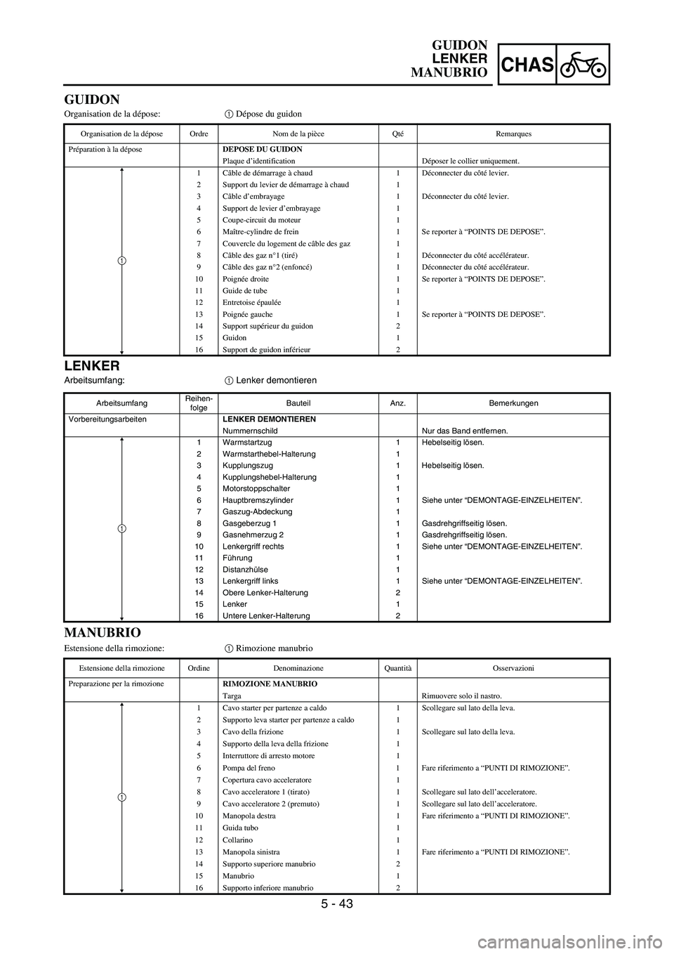
1 Handlebar removal
Extent of removal Order Part name Q’ty Remarks
Preparation for removal
HANDLEBAR REMOVAL
Number plate Remove the band only.
1 Hot starter cable 1 Disconnect at the lever side.
2 Hot starter lever holder 1
3 Clutch cable 1 Disconnect at the lever side.
4 Clutch lever holder 1
5 Engine stop switch 1
6 Brake master cylinder 1 Refer to “REMOVAL POINTS”.
7 Throttle cable cap 1
8 Throttle cable #1 (pulled) 1 Disconnect at the throttle side.
9 Throttle cable #2 (pushed) 1 Disconnect at the throttle side.
10 Right grip 1 Refer to “REMOVAL POINTS”.
11 Tube guide 1
12 Collar 1
13 Left grip 1 Refer to “REMOVAL POINTS”.
14 Handlebar upper holder 2
15 Handlebar 1
16 Handlebar lower holder 2
1
Page 545 of 674
5 - 43
CHAS
LENKER
Arbeitsumfang:
1 Lenker demontieren
ArbeitsumfangReihen-
folgeBauteil Anz. Bemerkungen
VorbereitungsarbeitenLENKER DEMONTIEREN
Nummernschild Nur das Band entfernen.
1 Warmstartzug 1 Hebelseitig lösen.
2 Warmstarthebel-Halterung 1
3 Kupplungszug 1 Hebelseitig lösen.
4 Kupplungshebel-Halterung 1
5 Motorstoppschalter 1
6 Hauptbremszylinder 1 Siehe unter “DEMONTAGE-EINZELHEITEN”.
7 Gaszug-Abdeckung 1
8 Gasgeberzug 1 1 Gasdrehgriffseitig lösen.
9 Gasnehmerzug 2 1 Gasdrehgriffseitig lösen.
10 Lenkergriff rechts 1 Siehe unter “DEMONTAGE-EINZELHEITEN”.
11 Führung 1
12 Distanzhülse 1
13 Lenkergriff links 1 Siehe unter “DEMONTAGE-EINZELHEITEN”.
14 Obere Lenker-Halterung 2
15 Lenker 1
16 Untere Lenker-Halterung 2
1
GUIDON
Organisation de la dépose:1 Dépose du guidon
Organisation de la dépose Ordre Nom de la pièce QtéRemarques
Préparation à la dépose
DEPOSE DU GUIDON
Plaque d’identification Déposer le collier uniquement.
1Câble de démarrage à chaud 1 Déconnecter du côté levier.
2 Support du levier de démarrage à chaud 1
3Câble d’embrayage 1 Déconnecter du côté levier.
4 Support de levier d’embrayage 1
5 Coupe-circuit du moteur 1
6Maître-cylindre de frein 1 Se reporter à “POINTS DE DEPOSE”.
7 Couvercle du logement de câble des gaz 1
8Câble des gaz n°1 (tiré)1Déconnecter du côté accélérateur.
9Câble des gaz n°2 (enfoncé)1Déconnecter du côté accélérateur.
10 Poignée droite 1 Se reporter à “POINTS DE DEPOSE”.
11 Guide de tube 1
12 Entretoise épaulée1
13 Poignée gauche 1 Se reporter à “POINTS DE DEPOSE”.
14 Support supérieur du guidon 2
15 Guidon 1
16 Support de guidon inférieur 2
1
MANUBRIO
Estensione della rimozione:1 Rimozione manubrio
Estensione della rimozione Ordine Denominazione QuantitàOsservazioni
Preparazione per la rimozione
RIMOZIONE MANUBRIO
Targa Rimuovere solo il nastro.
1 Cavo starter per partenze a caldo 1 Scollegare sul lato della leva.
2 Supporto leva starter per partenze a caldo 1
3 Cavo della frizione 1 Scollegare sul lato della leva.
4 Supporto della leva della frizione 1
5 Interruttore di arresto motore 1
6 Pompa del freno 1 Fare riferimento a “PUNTI DI RIMOZIONE”.
7 Copertura cavo acceleratore 1
8 Cavo acceleratore 1 (tirato) 1 Scollegare sul lato dell’acceleratore.
9 Cavo acceleratore 2 (premuto) 1 Scollegare sul lato dell’acceleratore.
10 Manopola destra 1 Fare riferimento a “PUNTI DI RIMOZIONE”.
11 Guida tubo 1
12 Collarino 1
13 Manopola sinistra 1 Fare riferimento a “PUNTI DI RIMOZIONE”.
14 Supporto superiore manubrio 2
15 Manubrio 1
16 Supporto inferiore manubrio 2
1
GUIDON
LENKER
MANUBRIO
Page 546 of 674
5 - 44
CHAS
EC5B3000
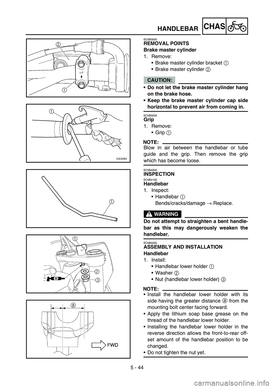
REMOVAL POINTS
Brake master cylinder
1. Remove:
Brake master cylinder bracket 1
Brake master cylinder 2
CAUTION:
Do not let the brake master cylinder hang
on the brake hose.
Keep the brake master cylinder cap side
horizontal to prevent air from coming in.
EC5B3200
Grip
1. Remove:
Grip 1
NOTE:
Blow in air between the handlebar or tube
guide and the grip. Then remove the grip
which has become loose.
EC5B4000
INSPECTION
EC5B4100
Handlebar
1. Inspect:
Handlebar 1
Bends/cracks/damage → Replace.
WARNING
Do not attempt to straighten a bent handle-
bar as this may dangerously weaken the
handlebar.
EC5B5000
ASSEMBLY AND INSTALLATION
Handlebar
1. Install:
Handlebar lower holder 1
Washer 2
Nut (handlebar lower holder) 3
NOTE:
Install the handlebar lower holder with its
side having the greater distance a from the
mounting bolt center facing forward.
Apply the lithium soap base grease on the
thread of the handlebar lower holder.
Installing the handlebar lower holder in the
reverse direction allows the front-to-rear off-
set amount of the handlebar position to be
changed.
Do not tighten the nut yet.
HANDLEBAR
Page 547 of 674
5 - 44
CHAS
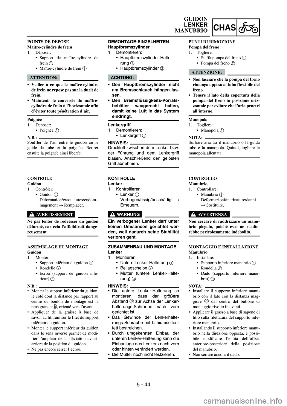
DEMONTAGE-EINZELHEITEN
Hauptbremszylinder
1. Demontieren:
Hauptbremszylinder-Halte-
rung
1
Hauptbremszylinder
2
ACHTUNG:
Den Hauptbremszylinder nicht
am Bremsschlauch hängen las-
sen.
Den Bremsflüssigkeits-Vorrats-
behälter waagerecht halten,
damit keine Luft in das System
eindringt.
Lenkergriff
1. Demontieren:
Lenkergriff
1
HINWEIS:
Druckluft zwischen dem Lenker bzw.
der Führung und dem Lenkergriff
blasen. Anschließend den gelösten
Griff abnehmen.
KONTROLLE
Lenker
1. Kontrollieren:
Lenker
1
Verbogen/rissig/beschädigt
→
Erneuern.
WARNUNG
Ein verbogener Lenker darf unter
keinen Umständen gerichtet wer-
den, weil dadurch seine Stabilität
verloren geht.
ZUSAMMENBAU UND MONTAGE
Lenker
1. Montieren:
Untere Lenker-Halterung
1
Beilagscheibe
2
Mutter (untere Lenker-Halte-
rung)
3
HINWEIS:
Die untere Lenker-Halterung so
montieren, dass der größere
Abstand
a zur Achse der Lenker-
halterungs-Schraube nach vorn
gerichtet ist.
Das Gewinde der Lenkerhalte-
rungs-Schraube mit Lithiumseifen-
fett bestreichen.
Durch umgekehrten Einbau der
unteren Lenker-Halterung kann die
Einbaulage des Lenkers nach vorn
oder hinten verändert werden.
Die Mutter noch nicht festziehen. POINTS DE DEPOSE
Maître-cylindre de frein
1. Déposer:
Support de maître-cylindre de
frein 1
Maître-cylindre de frein 2
ATTENTION:
Veiller à ce que le maître-cylindre
de frein ne repose pas sur la durit de
frein.
Maintenir le couvercle du maître-
cylindre de frein à l’horizontale afin
d’éviter toute pénétration d’air.
Poignée
1. Déposer:
Poignée 1
N.B.:
Souffler de l’air entre le guidon ou le
guide de tube et la poignée. Retirer
ensuite la poignée ainsi libérée.
CONTROLE
Guidon
1. Contrôler:
Guidon 1
Déformation/craquelures/endom-
magement → Remplacer.
AVERTISSEMENT
Ne pas tenter de redresser un guidon
déformé, car cela l’affaiblirait dange-
reusement.
ASSEMBLAGE ET MONTAGE
Guidon
1. Monter:
Support inférieur du guidon 1
Rondelle 2
Écrou (support de guidon infé-
rieur) 3
N.B.:
Monter le support inférieur du guidon,
le côté dont la distance par rapport au
centre du boulon de montage est la
plus grande a, orienté vers l’avant.
Appliquer de la graisse à base de
savon au lithium sur le filet du support
inférieur du guidon.
Monter le support inférieur du guidon
dans le sens inverse permet de modi-
fier l’ampleur de la déviation avant-
arrière de la position du guidon.
Ne pas encore serrer l’écrou.PUNTI DI RIMOZIONE
Pompa del freno
1. Togliere:
Staffa pompa del freno 1
Pompa del freno 2
ATTENZIONE:
Non lasciare che la pompa del freno
rimanga appesa al tubo flessibile del
freno.
Tenere il lato della copertura della
pompa del freno in posizione oriz-
zontale per evitare che l’aria penetri
all’interno.
Manopola
1. Togliere:
Manopola 1
NOTA:
Soffiare aria tra il manubrio o la guida
tubo e la manopola. Quindi, togliere la
manopola allentata.
CONTROLLO
Manubrio
1. Controllare:
Manubrio 1
Deformazioni/incrinature/danni
→ Sostituire.
AVVERTENZA
Non cercare di raddrizzare un manu-
brio piegato, poiché esso ne risulte-
rebbe pericolosamente indebolito.
MONTAGGIO E INSTALLAZIONE
Manubrio
1. Installare:
Supporto inferiore manubrio 1
Rondella 2
Dado (supporto inferiore manu-
brio) 3
NOTA:
Installare il supporto inferiore manu-
brio con il lato con la distanza mag-
giore a dal centro del bullone di
montaggio rivolto in avanti.
Applicare il grasso a base di sapone di
litio sulla filettatura del supporto infe-
riore manubrio.
Installando il supporto inferiore manu-
brio nella direzione opposta, è possi-
bile modificare l’entità dell’offset
anteriore-posteriore della posizione
del manubrio.
Non serrare ancora il dado.
GUIDON
LENKER
MANUBRIO
Page 548 of 674
5 - 45
CHAS
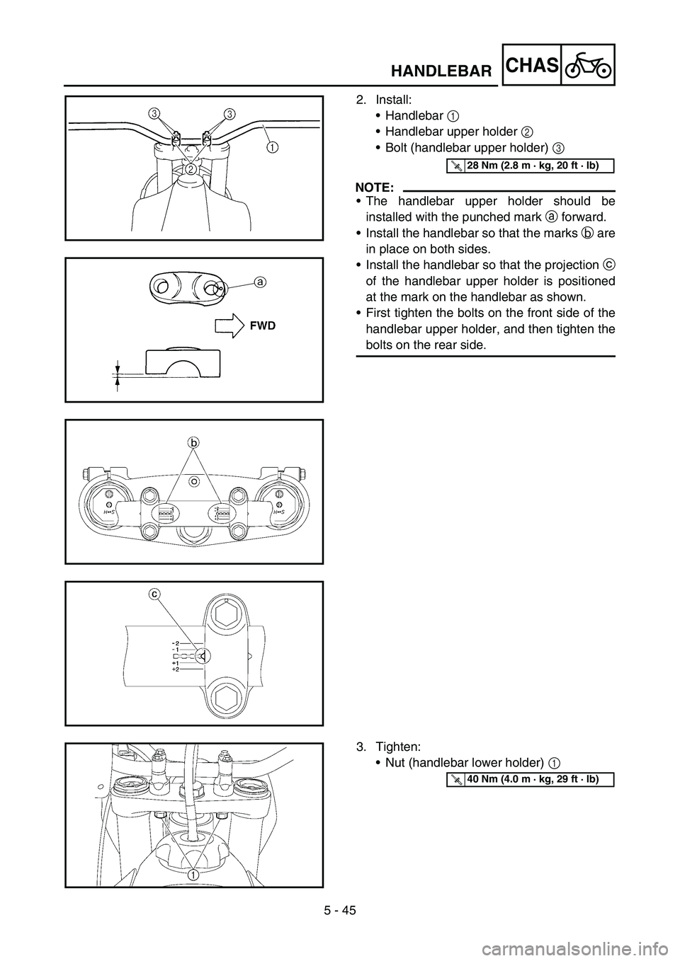
2. Install:
Handlebar 1
Handlebar upper holder 2
Bolt (handlebar upper holder) 3
NOTE:
The handlebar upper holder should be
installed with the punched mark a forward.
Install the handlebar so that the marks b are
in place on both sides.
Install the handlebar so that the projection c
of the handlebar upper holder is positioned
at the mark on the handlebar as shown.
First tighten the bolts on the front side of the
handlebar upper holder, and then tighten the
bolts on the rear side.
T R..28 Nm (2.8 m · kg, 20 ft · lb)
3. Tighten:
Nut (handlebar lower holder) 1
T R..40 Nm (4.0 m · kg, 29 ft · lb)
HANDLEBAR
Page 549 of 674
5 - 45
CHAS
2. Montieren:
Lenker
1
obere Lenker-Halterung
2
Schraube (obere Lenker-Hal-
terung)
3
HINWEIS:
Die obere Lenker-Halterung muss
so montiert werden, dass die Kör-
nermarkierung
a nach vorn
gerichtet ist.
Den Lenker so montieren, dass die
Markierungen
b an beiden Seiten
fluchten.
Den Lenker so montieren, dass
der Vorsprung
c der oberen Len-
ker-Halterung auf die Lenker-Mar-
kierung ausgerichtet ist, wie
dargestellt.
Zuerst die Schrauben an der Vor-
derseite festziehen, danach die
Schrauben an der Hinterseite vor-
schriftsmäßig festziehen.
T R..28 Nm (2,8 m · kg, 20 ft · lb)
3. Festziehen:
Mutter (Untere Lenker-Halte-
rung)
1
T R..40 Nm (4,0 m · kg, 29 ft · lb)
2. Monter:
Guidon 1
Support supérieur de guidon 2
Boulon (support supérieur de gui-
don) 3
N.B.:
Le support supérieur du guidon doit
être monté avec son poinçon a vers
l’avant.
Monter le guidon de manière que les
repères b soient en place des deux
côtés.
Monter le guidon de manière à ce que
l’ergot c du support du guidon supé-
rieur soit positionné selon le repère
d’alignement situé sur le guidon,
comme indiqué.
Serrer d’abord les boulons situés à
l’avant du support supérieur du gui-
don, puis serrer les boulons situés à
l’arrière.
T R..28 Nm (2,8 m · kg, 20 ft · lb)
3. Serrer:
Ecrou (Support de guidon infé-
rieur) 1
T R..40 Nm (4,0 m · kg, 29 ft · lb)
2. Installare:
Manubrio 1
Supporto superiore manubrio 2
Bullone (supporto superiore
manubrio) 3
NOTA:
Il supporto superiore del manubrio
deve essere installato con il riferi-
mento punzonato a rivolto in avanti.
Installare il manubrio in modo che i
contrassegni b siano in posizione su
entrambi i lati.
Installare il manubrio in modo che la
sporgenza c del supporto superiore
del manubrio sia posizionata sul con-
trassegno sul manubrio, come illu-
strato.
Serrare prima i bulloni sul lato ante-
riore del supporto superiore manubrio,
quindi quelli sul lato posteriore.
T R..28 Nm (2,8 m · kg, 20 ft · lb)
3. Serrare:
Dado (Supporto inferiore manu-
brio) 1
T R..40 Nm (4,0 m · kg, 29 ft · lb)
GUIDON
LENKER
MANUBRIO
Page 550 of 674
5 - 46
CHASHANDLEBAR
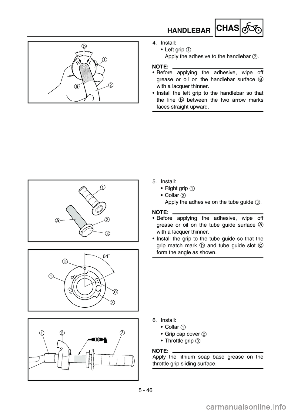
4. Install:
Left grip 1
Apply the adhesive to the handlebar 2.
NOTE:
Before applying the adhesive, wipe off
grease or oil on the handlebar surface a
with a lacquer thinner.
Install the left grip to the handlebar so that
the line b between the two arrow marks
faces straight upward.
5. Install:
Right grip 1
Collar 2
Apply the adhesive on the tube guide 3.
NOTE:
Before applying the adhesive, wipe off
grease or oil on the tube guide surface a
with a lacquer thinner.
Install the grip to the tube guide so that the
grip match mark b and tube guide slot c
form the angle as shown.
R
L
64˚
3 1b
c
6. Install:
•Collar 1
• Grip cap cover 2
• Throttle grip 3
NOTE:
Apply the lithium soap base grease on the
throttle grip sliding surface.