steering wheel YAMAHA YZ250F 2008 Betriebsanleitungen (in German)
[x] Cancel search | Manufacturer: YAMAHA, Model Year: 2008, Model line: YZ250F, Model: YAMAHA YZ250F 2008Pages: 192, PDF-Größe: 7.03 MB
Page 10 of 192
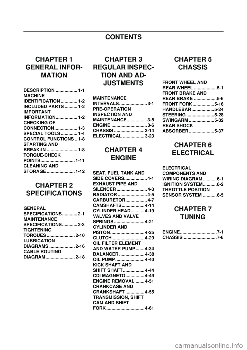
CONTENTS
CHAPTER 1
GENERAL INFOR-
MATION
DESCRIPTION ................. 1-1
MACHINE
IDENTIFICATION ............. 1-2
INCLUDED PARTS .......... 1-2
IMPORTANT
INFORMATION................. 1-2
CHECKING OF
CONNECTION .................. 1-3
SPECIAL TOOLS ............. 1-4
CONTROL FUNCTIONS .. 1-8
STARTING AND
BREAK-IN ........................ 1-8
TORQUE-CHECK
POINTS........................... 1-11
CLEANING AND
STORAGE ...................... 1-12
CHAPTER 2
SPECIFICATIONS
GENERAL
SPECIFICATIONS ............ 2-1
MAINTENANCE
SPECIFICATIONS ............ 2-3
TIGHTENING
TORQUES ...................... 2-10
LUBRICATION
DIAGRAMS .................... 2-16
CABLE ROUTING
DIAGRAM ....................... 2-18
CHAPTER 3
REGULAR INSPEC-
TION AND AD-JUSTMENTS
MAINTENANCE
INTERVALS ...................... 3-1
PRE-OPERATION
INSPECTION AND
MAINTENANCE................ 3-5
ENGINE ............................ 3-6
CHASSIS ........................ 3-14
ELECTRICAL ................. 3-23
CHAPTER 4 ENGINE
SEAT, FUEL TANK AND
SIDE COVERS.................. 4-1
EXHAUST PIPE AND
SILENCER ........................ 4-3
RADIATOR ....................... 4-5
CARBURETOR................. 4-7
CAMSHAFTS.................. 4-14
CYLINDER HEAD........... 4-19
VALVES AND VALVE
SPRINGS ........................ 4-21
CYLINDER AND
PISTON ........................... 4-25
CLUTCH ......................... 4-29
OIL FILTER ELEMENT
AND WATER PUMP ....... 4-34
BALANCER .................... 4-38
OIL PUMP ....................... 4-40
KICK SHAFT AND
SHIFT SHAFT ................. 4-44
CDI MAGNETO............... 4-49
ENGINE REMOVAL ....... 4-51
CRANKCASE AND
CRANKSHAFT ............... 4-55
TRANSMISSION, SHIFT
CAM AND SHIFT
FORK .............................. 4-61
CHAPTER 5CHASSIS
FRONT WHEEL AND
REAR WHEEL ..................5-1
FRONT BRAKE AND
REAR BRAKE ..................5-6
FRONT FORK ................. 5-16
HANDLEBAR..................5-24
STEERING ......................5-28
SWINGARM ....................5-32
REAR SHOCK
ABSORBER ....................5-37
CHAPTER 6
ELECTRICAL
ELECTRICAL
COMPONENTS AND
WIRING DIAGRAM ...........6-1
IGNITION SYSTEM...........6-2
THROTTLE POSITION
SENSOR SYSTEM ...........6-5
CHAPTER 7
TUNING
ENGINE.............................7-1
CHASSIS ..........................7-6
Page 21 of 192

1-11
TORQUE-CHECK POINTS
TORQUE-CHECK POINTS
Concerning the tightening torque, refer to "TIGHTENING TORQUES" section in the CHAPTER 2.
Frame constructionFrame to rear frame
Combined seat and fuel tank Fuel tank to frame
Exhaust system Silencer to rear frame
Engine mounting Frame to engine
Engine bracket to engine
Engine bracket to frame
Steering Steering stem to handlebar Steering stem to frame
Steering stem to upper bracket
Upper bracket to handlebar
Suspension Front Steering stem to front fork Front fork to upper bracket
Front fork to lower bracket
Rear For link type Assembly of links
Link to frame
Link to rear shock absorber
Link to swingarm
Installation of rear shock absorber Rear shock absorber to frame
Installation of swingarm Tightening of pivot shaft
Wheel Installation of wheel Front Tightening of wheel axle
Tightening of axle holder
Rear Tightening of wheel axle Wheel to rear wheel sprocket
Brake Front Brake caliper to front fork
Brake disc to wheel
Tightening of union bolt
Brake master cylinder to handlebar
Tightening of bleed screw
Tightening of brake hose holder
Rear Brake pedal to frame Brake disc to wheel
Tightening of union bolt
Brake master cylinder to frame
Tightening of bleed screw
Tightening of brake hose holder
Fuel system Fuel tank to fuel cock
Lubrication system Tightening of oil hose clamp
Page 30 of 192
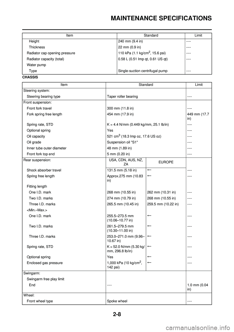
2-8
MAINTENANCE SPECIFICATIONS
CHASSISHeight
240 mm (9.4 in)----
Thickness 22 mm (0.9 in)----
Radiator cap opening pressure 110 kPa (1.1 kg/cm
2, 15.6 psi)----
Radiator capacity (total) 0.58 L (0.51 Imp qt, 0.61 US qt)----
Water pump Type Single-suction centrifugal pump----
Item
StandardLimit
Item StandardLimit
Steering system: Steering bearing type Taper roller bearing----
Front suspension: Front fork travel 300 mm (11.8 in)----
Fork spring free length 454 mm (17.9 in)449 mm (17.7
in)
Spring rate, STD K = 4.4 N/mm (0.449 kg/mm, 25.1 lb/in)----
Optional spring Yes----
Oil capacity 521 cm
3 (18.3 lmp oz, 17.6 US oz)----
Oil grade Suspension oil "S1"----
Inner tube outer diameter 48 mm (1.89 in)----
Front fork top end 5 mm (0.20 in)----
Rear suspension: USA, CDN, AUS, NZ,
ZA EUROPE
Shock absorber travel 131.5 mm (5.18 in)
←----
Spring free length Approx.275 mm (10.83 in)
←----
Fitting length One I.D. mark 268 mm (10.55 in) 262 mm (10.31 in) ----
Two I.D. marks 274 mm (10.79 in) 268 mm (10.55 in) ----
Three I.D. marks 265.5 mm (10.45 in) 259.5 mm (10.22 in) ----
←----
Two I.D. marks 261.5–279.5 mm
(10.30–11.00 in)
←----
Three I.D. marks 253.0–271.0 mm (9.96–
10.67 in)
←----
Spring rate, STD K = 52.0 N/mm (5.30 kg/ mm, 296.8 lb/in)
←----
Optional spring Yes
←----
Enclosed gas pressure 1,000 kPa (10 kg/cm
2,
142 psi)←----
Swingarm: Swingarm free play limitEnd ---- 1.0 mm (0.04 in)
Wheel: Front wheel type Spoke wheel----
Page 34 of 192
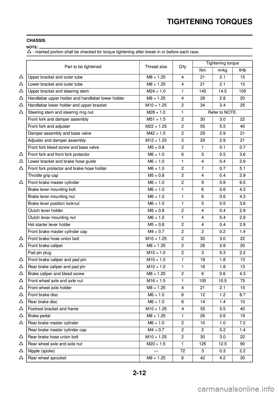
2-12
TIGHTENING TORQUES
CHASSIS
△- marked portion shall be checked for torque tightening after break-in or before each race.
Part to be tightenedThread size Q'tyTightening torque
Nm m•kg ft•lb
△Upper bracket and outer tube M8 × 1.25 4 21 2.1 15
△Lower bracket and outer tube M8 × 1.25 4 21 2.1 15
△Upper bracket and steering stem M24 × 1.0 1 145 14.5 105
△Handlebar upper holder and handlebar lower holderM8 × 1.25 4 28 2.8 20
△Handlebar lower holder and upper bracketM10 × 1.25 2 34 3.4 25
△Steering stem and steering ring nut M28 × 1.0 1Refer to NOTE.
Front fork and damper assembly M51 × 1.5 2 30 3.0 22
Front fork and adjuster M22 × 1.25 2 55 5.5 40
Damper assembly and base valve M42 × 1.5 2 29 2.9 21
Adjuster and damper assembly M12 × 1.25 2 29 2.9 21
Front fork bleed screw and base valve M5 × 0.8 2 1 0.1 0.7
△Front fork and front fork protector M6 × 1.0 6 5 0.5 3.6
△Lower bracket and brake hose guideM6 × 1.0 1 4 0.4 2.9
△Front fork protector and brake hose holderM6 × 1.0 2 7 0.7 5.1
Throttle grip cap M5 × 0.8 2 4 0.4 2.9
△Front brake master cylinderM6 × 1.0 2 9 0.9 6.5
Brake lever mounting bolt M6 × 1.0 1 6 0.6 4.3
Brake lever mounting nut M6 × 1.0 1 6 0.6 4.3
Brake lever position locknut M6 × 1.0 1 5 0.5 3.6
Clutch lever holder M5 × 0.8 2 4 0.4 2.9
Clutch lever mounting nut M6 × 1.0 1 4 0.4 2.9
Hot starter lever holder M5 × 0.8 2 4 0.4 2.9
Front brake master cylinder cap M4 × 0.7 2 2 0.2 1.4
△Front brake hose union boltM10 × 1.25 2 30 3.0 22
△Front brake caliper M8 × 1.25 2 28 2.8 20
Pad pin plug M10 × 1.0 2 3 0.3 2.2
△Front brake caliper and pad pinM10 × 1.0 1 18 1.8 13
△Rear brake caliper and pad pin M10 × 1.0 1 18 1.8 13
△Brake caliper and bleed screwM8 × 1.25 2 6 0.6 4.3
△Front wheel axle and axle nut M16 × 1.5 1 105 10.5 75
△Front wheel axle holderM8 × 1.25 4 21 2.1 15
△Front brake disc M6 × 1.0 6 12 1.2 8.7
△Rear brake disc M6 × 1.0 6 14 1.4 10
△Footrest bracket and frameM10 × 1.25 4 55 5.5 40
△Brake pedal M8 × 1.25 1 26 2.6 19
△Rear brake master cylinder M6 × 1.0 2 10 1.0 7.2
Rear brake master cylinder cap M4 × 0.7 2 2 0.2 1.4
△Rear brake hose union boltM10 × 1.25 2 30 3.0 22
△Rear wheel axle and axle nut M20 × 1.5 1 125 12.5 90
△Nipple (spoke) —72 3 0.3 2.2
△Rear wheel sprocket M8 × 1.25 6 42 4.2 30
Page 51 of 192
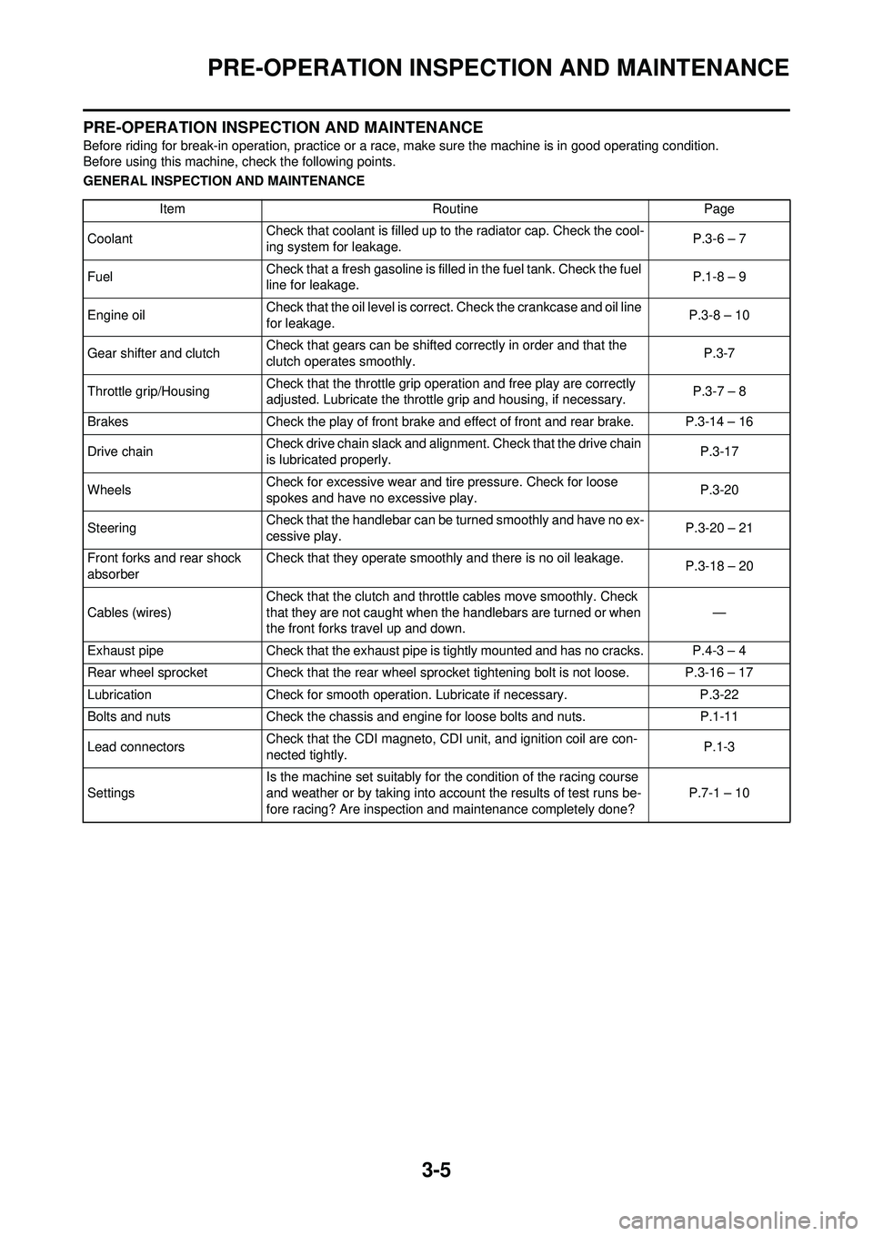
3-5
PRE-OPERATION INSPECTION AND MAINTENANCE
PRE-OPERATION INSPECTION AND MAINTENANCE
Before riding for break-in operation, practice or a race, make sure the machine is in good operating condition.
Before using this machine, check the following points.
GENERAL INSPECTION AND MAINTENANCEItem RoutinePage
Coolant Check that coolant is filled up to the radiator cap. Check the cool-
ing system for leakage. P.3-6 – 7
Fuel Check that a fresh gasoline is filled in the fuel tank. Check the fuel
line for leakage. P.1-8 – 9
Engine oil Check that the oil level is correct. Check the crankcase and oil line
for leakage. P.3-8 – 10
Gear shifter and clutch Check that gears can be shifted correctly in order and that the
clutch operates smoothly. P.3-7
Throttle grip/Housing Check that the throttle grip operation and free play are correctly
adjusted. Lubricate the throttle grip and housing, if necessary. P.3-7 – 8
Brakes Check the play of front brake and effect of front and rear brake. P.3-14 – 16
Drive chain Check drive chain slack and alignment. Check that the drive chain
is lubricated properly. P.3-17
Wheels Check for excessive wear and tire pressure. Check for loose
spokes and have no excessive play. P.3-20
Steering Check that the handlebar can be turned smoothly and have no ex-
cessive play. P.3-20 – 21
Front forks and rear shock
absorber Check that they operate smoothly and there is no oil leakage.
P.3-18 – 20
Cables (wires) Check that the clutch and throttle cables move smoothly. Check
that they are not caught when the handlebars are turned or when
the front forks travel up and down.
—
Exhaust pipe Check that the exhaust pipe is tightly mounted and has no cracks. P.4-3 – 4
Rear wheel sprocket Check that the rear wheel sprocket tightening bolt is not loose. P.3-16 – 17
Lubrication Check for smooth operation. Lubricate if necessary. P.3-22
Bolts and nuts Check the chassis and engine for loose bolts and nuts. P.1-11
Lead connectors Check that the CDI magneto, CDI unit, and ignition coil are con-
nected tightly. P.1-3
Settings Is the machine set suitably for the condition of the racing course
and weather or by taking into account the results of test runs be-
fore racing? Are inspection and maintenance completely done?
P.7-1 – 10
Page 66 of 192
3-20
CHASSIS
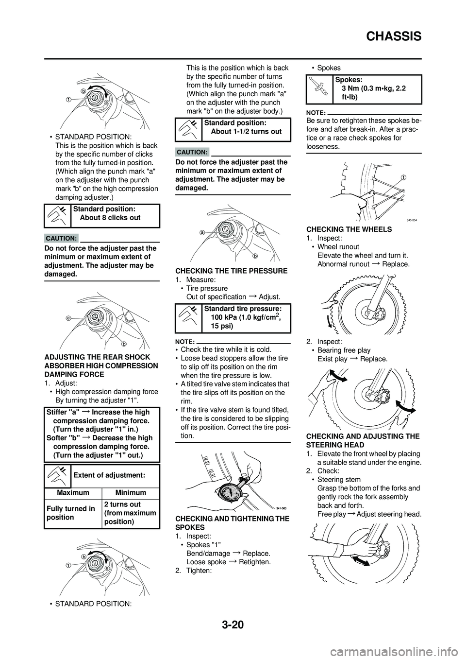
• STANDARD POSITION:This is the position which is back
by the specific number of clicks
from the fully turned-in position.
(Which align the punch mark "a"
on the adjuster with the punch
mark "b" on the high compression
damping adjuster.)
Do not force the adjuster past the
minimum or maximum extent of
adjustment. The adjuster may be
damaged.
ADJUSTING THE REAR SHOCK
ABSORBER HIGH COMPRESSION
DAMPING FORCE
1. Adjust:• High compression damping force
By turning the adjuster "1".
• STANDARD POSITION: This is the position which is back
by the specific number of turns
from the fully turned-in position.
(Which align the punch mark "a"
on the adjuster with the punch
mark "b" on the adjuster body.)
Do not force the adjuster past the
minimum or maximum extent of
adjustment. The adjuster may be
damaged.
CHECKING THE TIRE PRESSURE
1. Measure:
• Tire pressureOut of specification
→Adjust.
•Check the tire while it is cold.
• Loose bead stoppers allow the tire
to slip off its position on the rim
when the tire pressure is low.
• A tilted tire valve stem indicates that
the tire slips off its position on the
rim.
• If the tire valve stem is found tilted,
the tire is considered to be slipping
off its position. Correct the tire posi-
tion.
CHECKING AND TIGHTENING THE
SPOKES
1. Inspect:• Spokes "1"Bend/damage
→Replace.
Loose spoke
→Retighten.
2. Tighten: •Spokes
Be sure to retighten these spokes be-
fore and after break-in. After a prac-
tice or a race check spokes for
looseness.
CHECKING THE WHEELS
1. Inspect:
• Wheel runoutElevate the wheel and turn it.
Abnormal runout
→ Replace.
2. Inspect: • Bearing free play
Exist play
→Replace.
CHECKING AND ADJUSTING THE
STEERING HEAD
1. Elevate the front wheel by placing a suitable stand under the engine.
2. Check:
• Steering stemGrasp the bottom of the forks and
gently rock the fork assembly
back and forth.
Free play
→Adjust steering head.
Standard position:
About 8 clicks out
Stiffer "a"
→Increase the high
compression damping force.
(Turn the adjuster "1" in.)
Softer "b"
→Decrease the high
compression damping force.
(Turn the adjuster "1" out.)
Extent of adjustment:
Maximum Minimum
Fully turned in
position 2 turns out
(from maximum
position)
Standard position:
About 1-1/2 turns out
Standard tire pressure: 100 kPa (1.0 kgf/cm
2,
15 psi)
Spokes: 3 Nm (0.3 m•kg, 2.2
ft•lb)