tire pressure YAMAHA YZ250F 2008 Owners Manual
[x] Cancel search | Manufacturer: YAMAHA, Model Year: 2008, Model line: YZ250F, Model: YAMAHA YZ250F 2008Pages: 192, PDF Size: 7.03 MB
Page 24 of 192

2-2
GENERAL SPECIFICATIONS
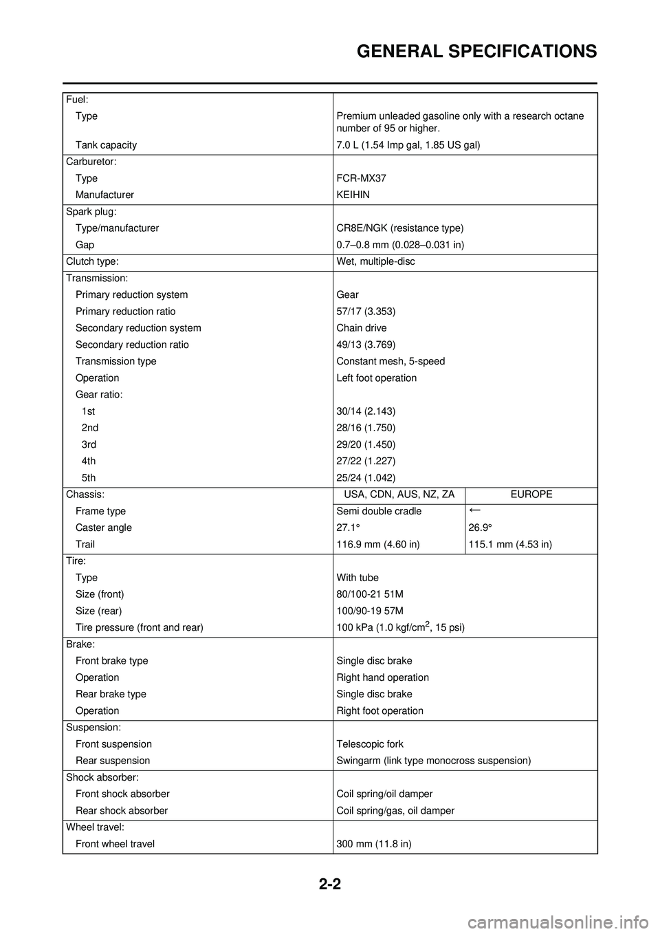
Fuel:Type Premium unleaded gasoline only with a research octane
number of 95 or higher.
Tank capacity 7.0 L (1.54 Imp gal, 1.85 US gal)
Carburetor: Type FCR-MX37
Manufacturer KEIHIN
Spark plug: Type/manufacturer CR8E/NGK (resistance type)
Gap 0.7–0.8 mm (0.028–0.031 in)
Clutch type: Wet, multiple-disc
Transmission: Primary reduction system Gear
Primary reduction ratio 57/17 (3.353)
Secondary reduction system Chain drive
Secondary reduction ratio 49/13 (3.769)
Transmission type Constant mesh, 5-speed
Operation Left foot operation
Gear ratio: 1st 30/14 (2.143)
2nd 28/16 (1.750)
3rd 29/20 (1.450)
4th 27/22 (1.227)
5th 25/24 (1.042)
Chassis: USA, CDN, AUS, NZ, ZAEUROPE
Frame type Semi double cradle
←
Caster angle27.1°26.9°
Trail 116.9 mm (4.60 in) 115.1 mm (4.53 in)
Tire: Type With tube
Size (front) 80/100-21 51M
Size (rear) 100/90-19 57M
Tire pressure (front and rear) 100 kPa (1.0 kgf/cm
2, 15 psi)
Brake: Front brake type Single disc brake
Operation Right hand operation
Rear brake type Single disc brake
Operation Right foot operation
Suspension: Front suspension Telescopic fork
Rear suspension Swingarm (link type monocross suspension)
Shock absorber: Front shock absorber Coil spring/oil damper
Rear shock absorber Coil spring/gas, oil damper
Wheel travel: Front wheel travel 300 mm (11.8 in)
Page 50 of 192

3-4
MAINTENANCE INTERVALS
TIRE, WHEELSInspect air pressure, wheel run-
out, tire wear and spoke loose-
ness
●●
Retighten sprocket bolt●●
Inspect bearings●
Replace bearings●
Lubricate●Lithium base grease
THROTTLE, CONTROL CABLE Check routing and connection
●●
Lubricate●●Yamaha cable lube or SAE 10W-30
motor oil
Inspect and clean (throttle ca-
ble)
●●Inspect dirt and wear on the throttle
cable on the carburetor side.
HOT STARTER, CLUTCH LEVER Inspect free play
●
Item After
break-
in Every
race
Every third
(or 500 km) Every
fifth (or 1,000 km)
As re-
quired Remarks
Page 51 of 192

3-5
PRE-OPERATION INSPECTION AND MAINTENANCE
PRE-OPERATION INSPECTION AND MAINTENANCE
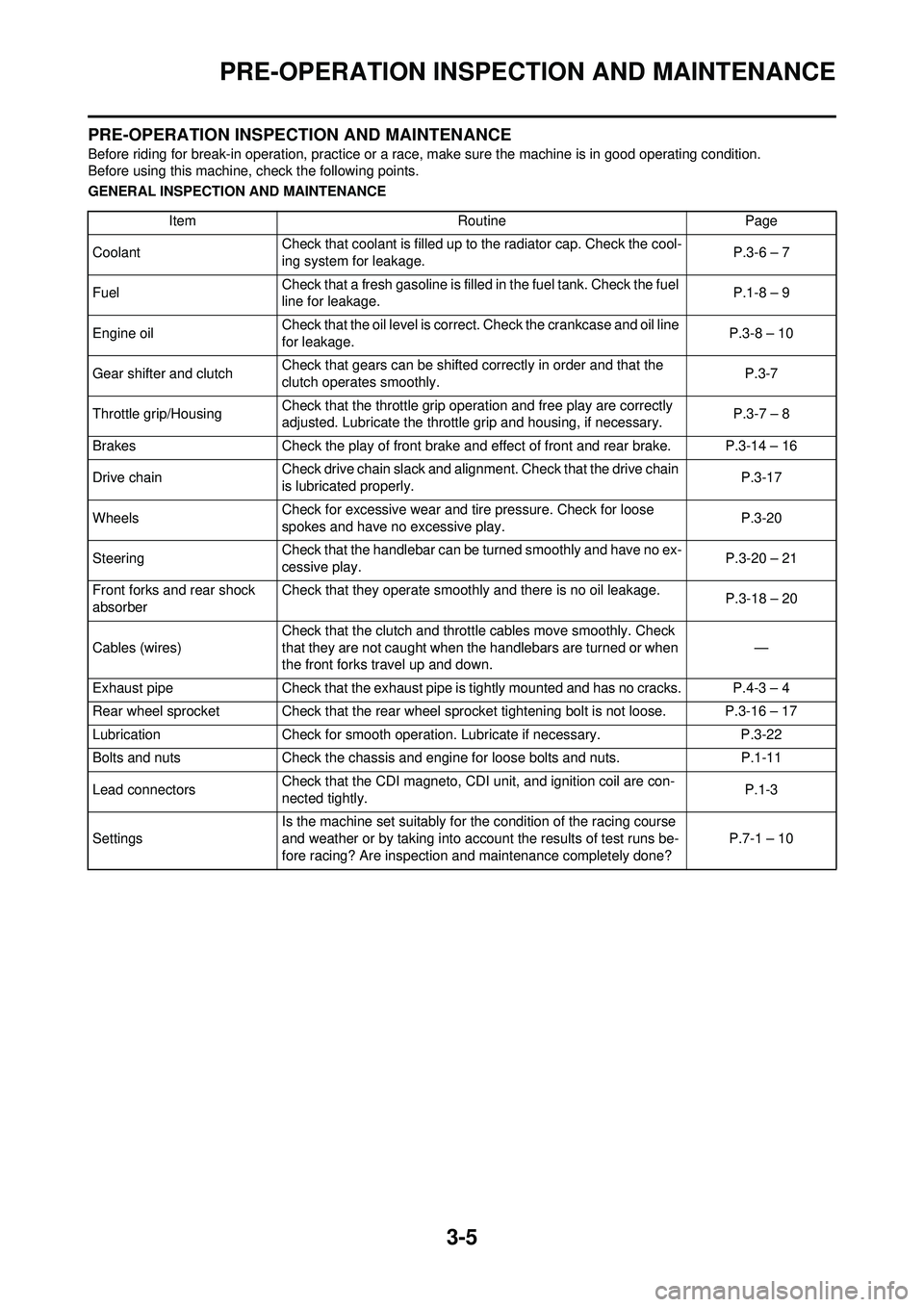
Before riding for break-in operation, practice or a race, make sure the machine is in good operating condition.
Before using this machine, check the following points.
GENERAL INSPECTION AND MAINTENANCEItem RoutinePage
Coolant Check that coolant is filled up to the radiator cap. Check the cool-
ing system for leakage. P.3-6 – 7
Fuel Check that a fresh gasoline is filled in the fuel tank. Check the fuel
line for leakage. P.1-8 – 9
Engine oil Check that the oil level is correct. Check the crankcase and oil line
for leakage. P.3-8 – 10
Gear shifter and clutch Check that gears can be shifted correctly in order and that the
clutch operates smoothly. P.3-7
Throttle grip/Housing Check that the throttle grip operation and free play are correctly
adjusted. Lubricate the throttle grip and housing, if necessary. P.3-7 – 8
Brakes Check the play of front brake and effect of front and rear brake. P.3-14 – 16
Drive chain Check drive chain slack and alignment. Check that the drive chain
is lubricated properly. P.3-17
Wheels Check for excessive wear and tire pressure. Check for loose
spokes and have no excessive play. P.3-20
Steering Check that the handlebar can be turned smoothly and have no ex-
cessive play. P.3-20 – 21
Front forks and rear shock
absorber Check that they operate smoothly and there is no oil leakage.
P.3-18 – 20
Cables (wires) Check that the clutch and throttle cables move smoothly. Check
that they are not caught when the handlebars are turned or when
the front forks travel up and down.
—
Exhaust pipe Check that the exhaust pipe is tightly mounted and has no cracks. P.4-3 – 4
Rear wheel sprocket Check that the rear wheel sprocket tightening bolt is not loose. P.3-16 – 17
Lubrication Check for smooth operation. Lubricate if necessary. P.3-22
Bolts and nuts Check the chassis and engine for loose bolts and nuts. P.1-11
Lead connectors Check that the CDI magneto, CDI unit, and ignition coil are con-
nected tightly. P.1-3
Settings Is the machine set suitably for the condition of the racing course
and weather or by taking into account the results of test runs be-
fore racing? Are inspection and maintenance completely done?
P.7-1 – 10
Page 66 of 192

3-20
CHASSIS
• STANDARD POSITION:This is the position which is back
by the specific number of clicks
from the fully turned-in position.
(Which align the punch mark "a"
on the adjuster with the punch
mark "b" on the high compression
damping adjuster.)
Do not force the adjuster past the
minimum or maximum extent of
adjustment. The adjuster may be
damaged.
ADJUSTING THE REAR SHOCK
ABSORBER HIGH COMPRESSION
DAMPING FORCE
1. Adjust:• High compression damping force
By turning the adjuster "1".
• STANDARD POSITION: This is the position which is back
by the specific number of turns
from the fully turned-in position.
(Which align the punch mark "a"
on the adjuster with the punch
mark "b" on the adjuster body.)
Do not force the adjuster past the
minimum or maximum extent of
adjustment. The adjuster may be
damaged.
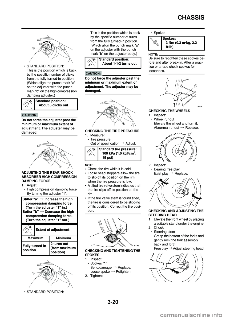
CHECKING THE TIRE PRESSURE
1. Measure:
• Tire pressureOut of specification
→Adjust.
•Check the tire while it is cold.
• Loose bead stoppers allow the tire
to slip off its position on the rim
when the tire pressure is low.
• A tilted tire valve stem indicates that
the tire slips off its position on the
rim.
• If the tire valve stem is found tilted,
the tire is considered to be slipping
off its position. Correct the tire posi-
tion.
CHECKING AND TIGHTENING THE
SPOKES
1. Inspect:• Spokes "1"Bend/damage
→Replace.
Loose spoke
→Retighten.
2. Tighten: •Spokes
Be sure to retighten these spokes be-
fore and after break-in. After a prac-
tice or a race check spokes for
looseness.
CHECKING THE WHEELS
1. Inspect:
• Wheel runoutElevate the wheel and turn it.
Abnormal runout
→ Replace.
2. Inspect: • Bearing free play
Exist play
→Replace.
CHECKING AND ADJUSTING THE
STEERING HEAD
1. Elevate the front wheel by placing a suitable stand under the engine.
2. Check:
• Steering stemGrasp the bottom of the forks and
gently rock the fork assembly
back and forth.
Free play
→Adjust steering head.
Standard position:
About 8 clicks out
Stiffer "a"
→Increase the high
compression damping force.
(Turn the adjuster "1" in.)
Softer "b"
→Decrease the high
compression damping force.
(Turn the adjuster "1" out.)
Extent of adjustment:
Maximum Minimum
Fully turned in
position 2 turns out
(from maximum
position)
Standard position:
About 1-1/2 turns out
Standard tire pressure: 100 kPa (1.0 kgf/cm
2,
15 psi)
Spokes: 3 Nm (0.3 m•kg, 2.2
ft•lb)
Page 186 of 192

7-6
CHASSIS
CHASSIS
SELECTION OF THE SECONDARY
REDUCTION RATIO (SPROCKET)
• It is generally said that the second-ary gear ratio should be reduced for
a longer straight portion of a speed
course and should be increased for
a course with many corners. Actual-
ly, however, as the speed depends
on the ground condition of the day
of the race, be sure to run through
the circuit to set the machine suit-
able for the entire course.
• In actuality, it is very difficult to achieve settings suitable for the en-
tire course and some settings may
be sacrificed. Thus, the settings
should be matched to the portion of
the course that has the greatest ef-
fect on the race result. In such a
case, run through the entire course
while making notes of lap times to
find the best balance; then, deter-
mine the secondary reduction ratio.
• If a course has a long straight por-
tion where a machine can run at
maximum speed, the machine is
generally set such that it can devel-
op its maximum revolutions toward
the end of the straight line, with care
taken to avoid the engine over-rev-
ving.
Riding technique varies from rider to
rider and the performance of a ma-
chine also vary from machine to ma-
chine. Therefore, do not imitate other
rider's settings from the beginning but
choose your own setting according to
the level of your riding technique.
DRIVE AND REAR WHEEL
SPROCKETS SETTING PARTS
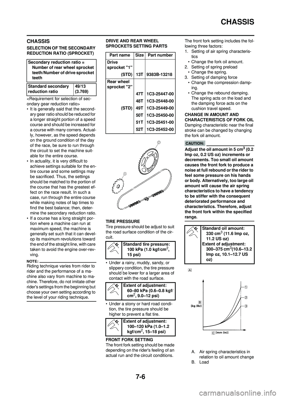
TIRE PRESSURE
Tire pressure should be adjust to suit
the road surface condition of the cir-
cuit.
• Under a rainy, muddy, sandy, or slippery condition, the tire pressure
should be lower for a larger area of
contact with the road surface.
• Under a stony or hard road condi- tion, the tire pressure should be
higher to prevent a flat tire.
FRONT FORK SETTING
The front fork setting should be made
depending on the rider's feeling of an
actual run and the circuit conditions. The front fork setting includes the fol-
lowing three factors:
1. Setting of air spring characteris-
tics
• Change the fork oil amount.
2. Setting of spring preload • Change the spring.
3. Setting of damping force • Change the compression damp-ing.
• Change the rebound damping. The spring acts on the load and
the damping force acts on the
cushion travel speed.
CHANGE IN AMOUNT AND
CHARACTERISTICS OF FORK OIL
Damping characteristic near the final
stroke can be changed by changing
the fork oil amount.
Adjust the oil amount in 5 cm3 (0.2
Imp oz, 0.2 US oz) increments or
decrements. Too small oil amount
causes the front fork to produce a
noise at full rebound or the rider to
feel some pressure on his hands
or body. Alternatively, too large oil
amount will cause the air spring
characteristics to have a tendency
to be stiffer with the consequent
deteriorated performance and
characteristics. Therefore, adjust
the front fork within the specified
range.
A. Air spring characteristics in relation to oil amount change
B. Load
Secondary reduction ratio =
Number of rear wheel sprocket
teeth/Number of drive sprocket
teeth
Standard secondary
reduction ratio 49/13
(3.769)
Part name Size Part number
Drive
sprocket "1" (STD) 13T 9383B-13218
Rear wheel
sprocket "2" 47T 1C3-25447-00
48T 1C3-25448-00
(STD) 49T 1C3-25449-00 50T 1C3-25450-00
51T 1C3-25451-00
52T 1C3-25452-00
Standard tire pressure: 100 kPa (1.0 kgf/cm
2,
15 psi)
Extent of adjustment: 60–80 kPa (0.6–0.8 kgf/
cm
2, 9.0–12 psi)
Extent of adjustment: 100–120 kPa (1.0–1.2
kgf/cm
2, 15–18 psi)
Standard oil amount:330 cm3 (11.6 Imp oz,
11.2 US oz)
Extent of adjustment: 300–375 cm
3(10.6–13.2
Imp oz, 10.1–12.7 US
oz)