wheel YAMAHA YZ250F 2008 Owners Manual
[x] Cancel search | Manufacturer: YAMAHA, Model Year: 2008, Model line: YZ250F, Model: YAMAHA YZ250F 2008Pages: 192, PDF Size: 7.03 MB
Page 10 of 192
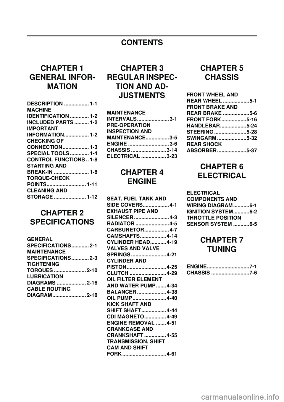
CONTENTS
CHAPTER 1
GENERAL INFOR-
MATION
DESCRIPTION ................. 1-1
MACHINE
IDENTIFICATION ............. 1-2
INCLUDED PARTS .......... 1-2
IMPORTANT
INFORMATION................. 1-2
CHECKING OF
CONNECTION .................. 1-3
SPECIAL TOOLS ............. 1-4
CONTROL FUNCTIONS .. 1-8
STARTING AND
BREAK-IN ........................ 1-8
TORQUE-CHECK
POINTS........................... 1-11
CLEANING AND
STORAGE ...................... 1-12
CHAPTER 2
SPECIFICATIONS
GENERAL
SPECIFICATIONS ............ 2-1
MAINTENANCE
SPECIFICATIONS ............ 2-3
TIGHTENING
TORQUES ...................... 2-10
LUBRICATION
DIAGRAMS .................... 2-16
CABLE ROUTING
DIAGRAM ....................... 2-18
CHAPTER 3
REGULAR INSPEC-
TION AND AD-JUSTMENTS
MAINTENANCE
INTERVALS ...................... 3-1
PRE-OPERATION
INSPECTION AND
MAINTENANCE................ 3-5
ENGINE ............................ 3-6
CHASSIS ........................ 3-14
ELECTRICAL ................. 3-23
CHAPTER 4 ENGINE
SEAT, FUEL TANK AND
SIDE COVERS.................. 4-1
EXHAUST PIPE AND
SILENCER ........................ 4-3
RADIATOR ....................... 4-5
CARBURETOR................. 4-7
CAMSHAFTS.................. 4-14
CYLINDER HEAD........... 4-19
VALVES AND VALVE
SPRINGS ........................ 4-21
CYLINDER AND
PISTON ........................... 4-25
CLUTCH ......................... 4-29
OIL FILTER ELEMENT
AND WATER PUMP ....... 4-34
BALANCER .................... 4-38
OIL PUMP ....................... 4-40
KICK SHAFT AND
SHIFT SHAFT ................. 4-44
CDI MAGNETO............... 4-49
ENGINE REMOVAL ....... 4-51
CRANKCASE AND
CRANKSHAFT ............... 4-55
TRANSMISSION, SHIFT
CAM AND SHIFT
FORK .............................. 4-61
CHAPTER 5CHASSIS
FRONT WHEEL AND
REAR WHEEL ..................5-1
FRONT BRAKE AND
REAR BRAKE ..................5-6
FRONT FORK ................. 5-16
HANDLEBAR..................5-24
STEERING ......................5-28
SWINGARM ....................5-32
REAR SHOCK
ABSORBER ....................5-37
CHAPTER 6
ELECTRICAL
ELECTRICAL
COMPONENTS AND
WIRING DIAGRAM ...........6-1
IGNITION SYSTEM...........6-2
THROTTLE POSITION
SENSOR SYSTEM ...........6-5
CHAPTER 7
TUNING
ENGINE.............................7-1
CHASSIS ..........................7-6
Page 14 of 192

1-4
SPECIAL TOOLS
SPECIAL TOOLS
The proper special tools are necessary for complete and accurate tune-up and assembly. Using the correct special tool will
help prevent damage caused by the use of improper tools or improvised techniques. The shape and part number used for
the special tool differ by country, so two types are provided. Refer to the list provided to avoid errors when placing an order.
• For U.S.A. and Canada, use part number starting with "YM-", "YU-" or "ACC-".
• For others, use part number starting with "90890-".
Tool name/Part number How to useIllustration
Crankcase separating tool
YU-1135-A, 90890-01135 These tool is used to remove the
crankshaft from either case.
Flywheel puller
YM-1189, 90890-01189 This tool is used to remove the fly-
wheel magneto.
Rotor holding tool
YU-1235, 90890-01235 This tool is used when loosening or
tightening the flywheel magneto se-
curing nut.
Dial gauge and stand
YU-3097, 90890-01252
Stand
YU-1256 These tools are used to check each
part for runout or bent.
Crankshaft installing tool
Crankshaft installing pot
YU-90050, 90890-01274
Crankshaft installing bolt
YU-90050, 90890-01275
Spacer (crankshaft installer)
YU-91044, 90890-04081
Adapter (M12)
YU-90063, 90890-01278 These tools are used to install the
crankshaft.
Piston pin puller set
YU-1304, 90890-01304 This tool is used to remove the pis-
ton pin.
Page 21 of 192

1-11
TORQUE-CHECK POINTS
TORQUE-CHECK POINTS
Concerning the tightening torque, refer to "TIGHTENING TORQUES" section in the CHAPTER 2.
Frame constructionFrame to rear frame
Combined seat and fuel tank Fuel tank to frame
Exhaust system Silencer to rear frame
Engine mounting Frame to engine
Engine bracket to engine
Engine bracket to frame
Steering Steering stem to handlebar Steering stem to frame
Steering stem to upper bracket
Upper bracket to handlebar
Suspension Front Steering stem to front fork Front fork to upper bracket
Front fork to lower bracket
Rear For link type Assembly of links
Link to frame
Link to rear shock absorber
Link to swingarm
Installation of rear shock absorber Rear shock absorber to frame
Installation of swingarm Tightening of pivot shaft
Wheel Installation of wheel Front Tightening of wheel axle
Tightening of axle holder
Rear Tightening of wheel axle Wheel to rear wheel sprocket
Brake Front Brake caliper to front fork
Brake disc to wheel
Tightening of union bolt
Brake master cylinder to handlebar
Tightening of bleed screw
Tightening of brake hose holder
Rear Brake pedal to frame Brake disc to wheel
Tightening of union bolt
Brake master cylinder to frame
Tightening of bleed screw
Tightening of brake hose holder
Fuel system Fuel tank to fuel cock
Lubrication system Tightening of oil hose clamp
Page 22 of 192
1-12
CLEANING AND STORAGE
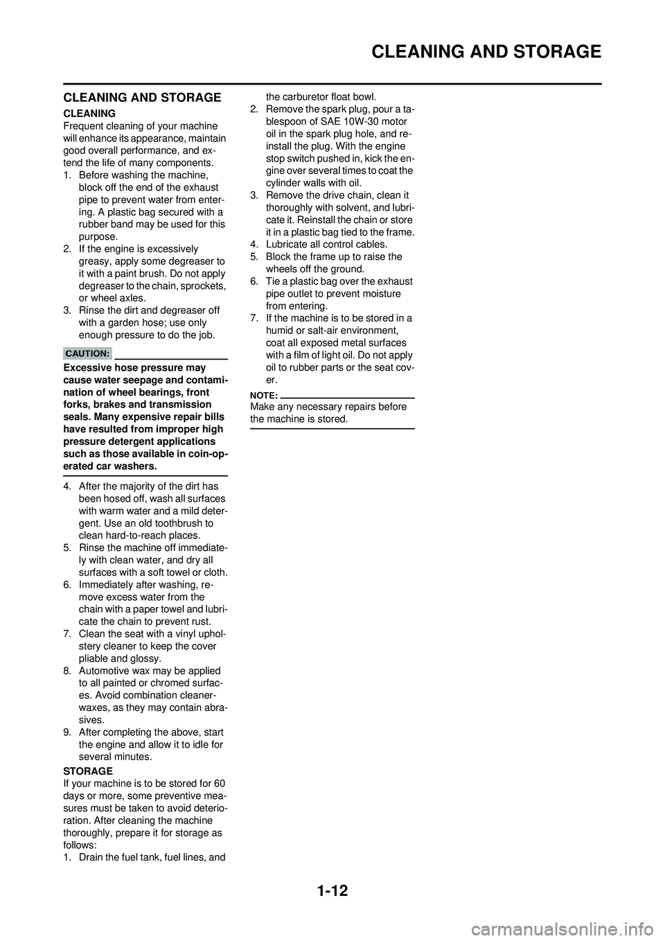
CLEANING AND STORAGE
CLEANING
Frequent cleaning of your machine
will enhance its appearance, maintain
good overall performance, and ex-
tend the life of many components.
1. Before washing the machine, block off the end of the exhaust
pipe to prevent water from enter-
ing. A plastic bag secured with a
rubber band may be used for this
purpose.
2. If the engine is excessively greasy, apply some degreaser to
it with a paint brush. Do not apply
degreaser to the chain, sprockets,
or wheel axles.
3. Rinse the dirt and degreaser off with a garden hose; use only
enough pressure to do the job.
Excessive hose pressure may
cause water seepage and contami-
nation of wheel bearings, front
forks, brakes and transmission
seals. Many expensive repair bills
have resulted from improper high
pressure detergent applications
such as those available in coin-op-
erated car washers.
4. After the majority of the dirt has been hosed off, wash all surfaces
with warm water and a mild deter-
gent. Use an old toothbrush to
clean hard-to-reach places.
5. Rinse the machine off immediate- ly with clean water, and dry all
surfaces with a soft towel or cloth.
6. Immediately after washing, re- move excess water from the
chain with a paper towel and lubri-
cate the chain to prevent rust.
7. Clean the seat with a vinyl uphol- stery cleaner to keep the cover
pliable and glossy.
8. Automotive wax may be applied to all painted or chromed surfac-
es. Avoid combination cleaner-
waxes, as they may contain abra-
sives.
9. After completing the above, start the engine and allow it to idle for
several minutes.
STORAGE
If your machine is to be stored for 60
days or more, some preventive mea-
sures must be taken to avoid deterio-
ration. After cleaning the machine
thoroughly, prepare it for storage as
follows:
1. Drain the fuel tank, fuel lines, and the carburetor float bowl.
2. Remove the spark plug, pour a ta- blespoon of SAE 10W-30 motor
oil in the spark plug hole, and re-
install the plug. With the engine
stop switch pushed in, kick the en-
gine over several times to coat the
cylinder walls with oil.
3. Remove the drive chain, clean it thoroughly with solvent, and lubri-
cate it. Reinstall the chain or store
it in a plastic bag tied to the frame.
4. Lubricate all control cables.
5. Block the frame up to raise the
wheels off the ground.
6. Tie a plastic bag over the exhaust
pipe outlet to prevent moisture
from entering.
7. If the machine is to be stored in a
humid or salt-air environment,
coat all exposed metal surfaces
with a film of light oil. Do not apply
oil to rubber parts or the seat cov-
er.
Make any necessary repairs before
the machine is stored.
Page 23 of 192

2-1
GENERAL SPECIFICATIONS
SPECIFICATIONS
GENERAL SPECIFICATIONS
Model name:YZ250FX (USA, CDN, AUS, NZ)
YZ250F (EUROPE, ZA)
Model code number: 5XCL (USA,CDN)
5XCM (EUROPE)
5XCP (AUS, NZ, ZA)
Dimensions: USA, CDN, ZA, AUS, NZEUROPE
Overall length 2,162 mm (85.12 in) 2,165 mm (85.24 in)
Overall width 825 mm (32.48 in)
←
Overall height1,300 mm (51.18 in)←
Seat height 985 mm (38.78 in)997 mm (39.25 in)
Wheelbase 1,469 mm (57.83 in)
←
Minimum ground clearance370 mm (14.57 in)372 mm (14.65 in)
Dry weight: Without oil and fuel 92.7 kg (204 lb)
Engine: Engine type Liquid cooled 4-stroke, DOHC
Cylinder arrangement Single cylinder, forward inclined
Displacement 249 cm
3 (8.76 Imp oz, 8.42 US oz)
Bore × stroke 77.0 × 53.6 mm (3.03 × 2.11 in)
Compression ratio 13.5 : 1
Starting system Kickstarter
Lubrication system: Dry sump
Oil type or grade: Engine oil (For USA and CDN)
Yamalube 4, SAE10W30 or SAE20W40
Yamalube 4-R, SAE10W50
API service SG type or higher,
JASO standard MA
(Except for USA and CDN)
SAE10W30, SAE10W40, SAE15W40,
SAE20W40 or SAE20W50
API service SG type or higher,
JASO standard MA
Oil capacity: Engine oilPeriodic oil change 1.05 L (0.92 Imp qt, 1.11 US qt)
With oil filter replacement 1.15 L (1.01 Imp qt, 1.22 US qt)
Total amount 1.30 L (1.14 Imp qt, 1.37 US qt)
Coolant capacity (including all routes): 0.99 L (0.87 Imp qt, 1.05 US qt)
Air filter: Wet type element
2
Page 24 of 192
2-2
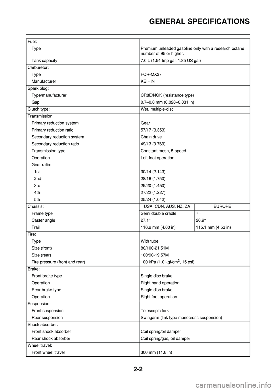
GENERAL SPECIFICATIONS
Fuel:Type Premium unleaded gasoline only with a research octane
number of 95 or higher.
Tank capacity 7.0 L (1.54 Imp gal, 1.85 US gal)
Carburetor: Type FCR-MX37
Manufacturer KEIHIN
Spark plug: Type/manufacturer CR8E/NGK (resistance type)
Gap 0.7–0.8 mm (0.028–0.031 in)
Clutch type: Wet, multiple-disc
Transmission: Primary reduction system Gear
Primary reduction ratio 57/17 (3.353)
Secondary reduction system Chain drive
Secondary reduction ratio 49/13 (3.769)
Transmission type Constant mesh, 5-speed
Operation Left foot operation
Gear ratio: 1st 30/14 (2.143)
2nd 28/16 (1.750)
3rd 29/20 (1.450)
4th 27/22 (1.227)
5th 25/24 (1.042)
Chassis: USA, CDN, AUS, NZ, ZAEUROPE
Frame type Semi double cradle
←
Caster angle27.1°26.9°
Trail 116.9 mm (4.60 in) 115.1 mm (4.53 in)
Tire: Type With tube
Size (front) 80/100-21 51M
Size (rear) 100/90-19 57M
Tire pressure (front and rear) 100 kPa (1.0 kgf/cm
2, 15 psi)
Brake: Front brake type Single disc brake
Operation Right hand operation
Rear brake type Single disc brake
Operation Right foot operation
Suspension: Front suspension Telescopic fork
Rear suspension Swingarm (link type monocross suspension)
Shock absorber: Front shock absorber Coil spring/oil damper
Rear shock absorber Coil spring/gas, oil damper
Wheel travel: Front wheel travel 300 mm (11.8 in)
Page 25 of 192

2-3
MAINTENANCE SPECIFICATIONS
MAINTENANCE SPECIFICATIONS
ENGINERear wheel travel
306 mm (12.0 in)
Electrical: Ignition system CDI magneto
ItemStandardLimit
Cylinder head: Warp limit ----0.05 mm (0.002
in)
Cylinder: Bore size 77.00–77.01 mm (3.0315–3.0319 in) ----
Out of round limit ----0.05 mm (0.002
in)
Camshaft: Drive method Chain drive (Left)----
Camshaft cap inside diameter 22.000–22.021 mm (0.8661–0.8670 in) ----
Camshaft outside diameter 21.959–21.972 mm (0.8645–0.8650 in) ----
Shaft-to-cap clearance 0.028–0.062 mm (0.0011–0.0024 in) 0.08 mm (0.003
in)
Cam dimensions
Intake "A" 30.246–30.346 mm (1.1908–1.1947 in) 30.146 mm
(1.1869 in)
Intake "B" 22.45–22.55 mm (0.8839–0.8878 in) 22.35 mm
(0.8799 in)
Exhaust "A" 30.399–30.499 mm (1.1968–1.2007 in) 30.299 mm
(1.1929 in)
Exhaust "B" 22.45–22.55 mm (0.8839–0.8878 in) 22.35 mm
(0.8799 in)
Camshaft runout limit ----0.03 mm
(0.0012 in)
Timing chain: Timing chain type/No. of links 92RH2010-114M/114----
Timing chain adjustment method Automatic----
Page 30 of 192
2-8
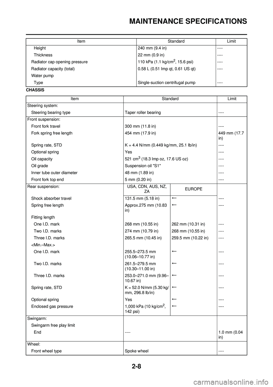
MAINTENANCE SPECIFICATIONS
CHASSISHeight
240 mm (9.4 in)----
Thickness 22 mm (0.9 in)----
Radiator cap opening pressure 110 kPa (1.1 kg/cm
2, 15.6 psi)----
Radiator capacity (total) 0.58 L (0.51 Imp qt, 0.61 US qt)----
Water pump Type Single-suction centrifugal pump----
Item
StandardLimit
Item StandardLimit
Steering system: Steering bearing type Taper roller bearing----
Front suspension: Front fork travel 300 mm (11.8 in)----
Fork spring free length 454 mm (17.9 in)449 mm (17.7
in)
Spring rate, STD K = 4.4 N/mm (0.449 kg/mm, 25.1 lb/in)----
Optional spring Yes----
Oil capacity 521 cm
3 (18.3 lmp oz, 17.6 US oz)----
Oil grade Suspension oil "S1"----
Inner tube outer diameter 48 mm (1.89 in)----
Front fork top end 5 mm (0.20 in)----
Rear suspension: USA, CDN, AUS, NZ,
ZA EUROPE
Shock absorber travel 131.5 mm (5.18 in)
←----
Spring free length Approx.275 mm (10.83 in)
←----
Fitting length One I.D. mark 268 mm (10.55 in) 262 mm (10.31 in) ----
Two I.D. marks 274 mm (10.79 in) 268 mm (10.55 in) ----
Three I.D. marks 265.5 mm (10.45 in) 259.5 mm (10.22 in) ----
←----
Two I.D. marks 261.5–279.5 mm
(10.30–11.00 in)
←----
Three I.D. marks 253.0–271.0 mm (9.96–
10.67 in)
←----
Spring rate, STD K = 52.0 N/mm (5.30 kg/ mm, 296.8 lb/in)
←----
Optional spring Yes
←----
Enclosed gas pressure 1,000 kPa (10 kg/cm
2,
142 psi)←----
Swingarm: Swingarm free play limitEnd ---- 1.0 mm (0.04 in)
Wheel: Front wheel type Spoke wheel----
Page 31 of 192
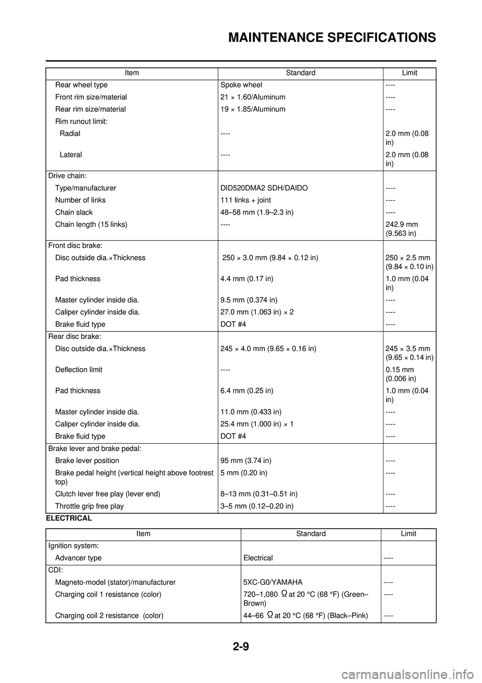
2-9
MAINTENANCE SPECIFICATIONS
ELECTRICALRear wheel type
Spoke wheel----
Front rim size/material 21 × 1.60/Aluminum----
Rear rim size/material 19 × 1.85/Aluminum----
Rim runout limit: Radial ---- 2.0 mm (0.08
in)
Lateral ---- 2.0 mm (0.08
in)
Drive chain: Type/manufacturer DID520DMA2 SDH/DAIDO ----
Number of links 111 links + joint----
Chain slack 48–58 mm (1.9–2.3 in)----
Chain length (15 links) ----242.9 mm
(9.563 in)
Front disc brake: Disc outside dia.×Thickness 250 × 3.0 mm (9.84 × 0.12 in)250 × 2.5 mm
(9.84 × 0.10 in)
Pad thickness 4.4 mm (0.17 in)1.0 mm (0.04
in)
Master cylinder inside dia. 9.5 mm (0.374 in)----
Caliper cylinder inside dia. 27.0 mm (1.063 in) × 2----
Brake fluid type DOT #4----
Rear disc brake: Disc outside dia.×Thickness 245 × 4.0 mm (9.65 × 0.16 in)245 × 3.5 mm
(9.65 × 0.14 in)
Deflection limit ----0.15 mm
(0.006 in)
Pad thickness 6.4 mm (0.25 in)1.0 mm (0.04
in)
Master cylinder inside dia. 11.0 mm (0.433 in)----
Caliper cylinder inside dia. 25.4 mm (1.000 in) × 1----
Brake fluid type DOT #4----
Brake lever and brake pedal: Brake lever position 95 mm (3.74 in)----
Brake pedal height (vertical height above footrest
top) 5 mm (0.20 in)
----
Clutch lever free play (lever end) 8–13 mm (0.31–0.51 in)----
Throttle grip free play 3–5 mm (0.12–0.20 in)----
Item
StandardLimit
Item StandardLimit
Ignition system: Advancer type Electrical----
CDI: Magneto-model (stator)/manufacturer 5XC-G0/YAMAHA----
Charging coil 1 resistance (color) 720–1,080
Ωat 20 °C (68 °F) (Green–
Brown) ----
Charging coil 2 resistance (color) 44–66
Ωat 20 °C (68 °F) (Black–Pink) ----
Page 33 of 192
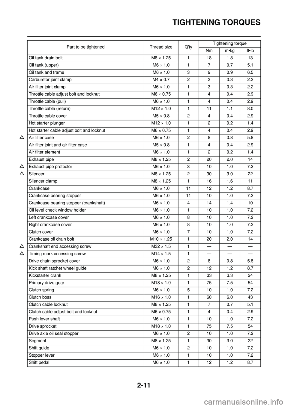
2-11
TIGHTENING TORQUES
Oil tank drain boltM8 × 1.25 1 18 1.8 13
Oil tank (upper) M6 × 1.0 1 7 0.7 5.1
Oil tank and frame M6 × 1.0 3 9 0.9 6.5
Carburetor joint clamp M4 × 0.7 2 3 0.3 2.2
Air filter joint clamp M6 × 1.0 1 3 0.3 2.2
Throttle cable adjust bolt and locknut M6 × 0.75 1 4 0.4 2.9
Throttle cable (pull) M6 × 1.0 1 4 0.4 2.9
Throttle cable (return) M12 × 1.0 1 11 1.1 8.0
Throttle cable cover M5 × 0.8 2 4 0.4 2.9
Hot starter plunger M12 × 1.0 1 2 0.2 1.4
Hot starter cable adjust bolt and locknut M6 × 0.75 1 4 0.4 2.9
△Air filter case M6 × 1.0 2 8 0.8 5.8
Air filter joint and air filter case M5 × 0.8 1 4 0.4 2.9
Air filter element M6 × 1.0 1 2 0.2 1.4
Exhaust pipe M8 × 1.25 2 20 2.0 14
△Exhaust pipe protector M6 × 1.0 3 10 1.0 7.2
△SilencerM8 × 1.25 2 30 3.0 22
Silencer clamp M8 × 1.25 1 16 1.6 11
Crankcase M6 × 1.0 11 12 1.2 8.7
Crankcase bearing stopper M6 × 1.0 11 10 1.0 7.2
Crankcase bearing stopper (crankshaft) M6 × 1.0 4 14 1.4 10
Oil level check window holder M6 × 1.0 1 10 1.0 7.2
Left crankcase cover M6 × 1.0 8 10 1.0 7.2
Right crankcase cover M6 × 1.0 8 10 1.0 7.2
Clutch cover M6 × 1.0 7 10 1.0 7.2
Crankcase oil drain bolt M10 × 1.25 1 20 2.0 14
△Crankshaft end accessing screw M32 × 1.5 1 — — —
△Timing mark accessing screwM14 × 1.5 1 — — —
Drive chain sprocket cover M6 × 1.0 2 8 0.8 5.8
Kick shaft ratchet wheel guide M6 × 1.0 2 12 1.2 8.7
Kickstarter crank M8 × 1.25 1 33 3.3 24
Primary drive gear M18 × 1.0 1 75 7.5 54
Clutch spring M6 × 1.0 5 10 1.0 7.2
Clutch boss M16 × 1.0 1 60 6.0 43
Clutch cable locknut M8 × 1.25 1 7 0.7 5.1
Clutch cable adjust bolt and locknut M6 × 0.75 1 4 0.4 2.9
Push lever shaft M6 × 1.0 1 10 1.0 7.2
Drive sprocket M18 × 1.0 1 75 7.5 54
Drive axle oil seal stopper M6 × 1.0 2 10 1.0 7.2
Segment M8 × 1.25 1 30 3.0 22
Shift guide M6 × 1.0 2 10 1.0 7.2
Stopper lever M6 × 1.0 1 10 1.0 7.2
Shift pedal M6 × 1.0 1 12 1.2 8.7
Part to be tightened
Thread size Q'tyTightening torque
Nm m•kg ft•lb