YAMAHA YZ250F 2010 Owners Manual
Manufacturer: YAMAHA, Model Year: 2010, Model line: YZ250F, Model: YAMAHA YZ250F 2010Pages: 196, PDF Size: 13.74 MB
Page 111 of 196
4-37
OIL FILTER ELEMENT AND WATER PUMP
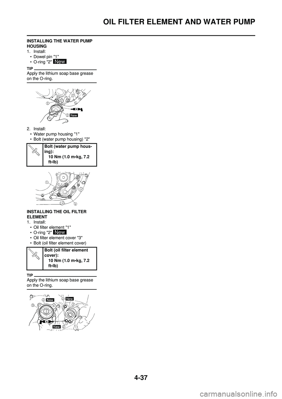
INSTALLING THE WATER PUMP
HOUSING
1. Install:• Dowel pin "1"
• O-ring "2"
Apply the lithium soap base grease
on the O-ring.
2. Install:
• Water pump housing "1"
• Bolt (water pump housing) "2"
INSTALLING THE OIL FILTER
ELEMENT
1. Install: • Oil filter element "1"
• O-ring "2"
• Oil filter element cover "3"
• Bolt (oil filter element cover)
Apply the lithium soap base grease
on the O-ring.
Bolt (water pump hous-
ing):
10 Nm (1.0 m•kg, 7.2
ft•lb)
Bolt (oil filter element
cover): 10 Nm (1.0 m•kg, 7.2
ft•lb)
Page 112 of 196
4-38
BALANCER
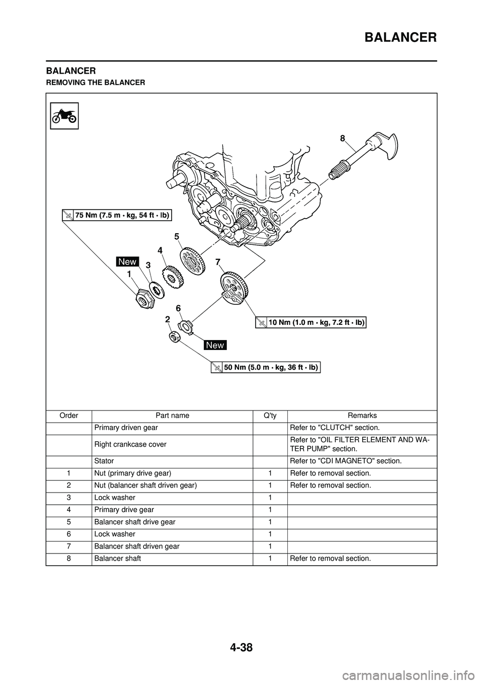
BALANCER
REMOVING THE BALANCEROrder Part name Q'ty Remarks Primary driven gear Refer to "CLUTCH" section.
Right crankcase cover Refer to "OIL FILTER ELEMENT AND WA-
TER PUMP" section.
Stator Refer to "CDI MAGNETO" section.
1 Nut (primary drive gear) 1 Refer to removal section.
2 Nut (balancer shaft driven gear) 1 Refer to removal section.
3 Lock washer 1
4 Primary drive gear 1
5 Balancer shaft drive gear 1
6 Lock washer 1
7 Balancer shaft driven gear 1
8 Balancer shaft 1 Refer to removal section.
Page 113 of 196
4-39
BALANCER
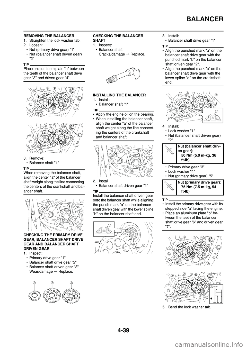
REMOVING THE BALANCER
1. Straighten the lock washer tab.
2. Loosen:• Nut (primary drive gear) "1"
• Nut (balancer shaft driven gear) "2"
Place an aluminum plate "a" between
the teeth of the balancer shaft drive
gear "3" and driven gear "4".
3. Remove:• Balancer shaft "1"
When removing the balancer shaft,
align the center "a" of the balancer
shaft weight along the line connecting
the centers of the crankshaft and bal-
ancer shaft.
CHECKING THE PRIMARY DRIVE
GEAR, BALANCER SHAFT DRIVE
GEAR AND BALANCER SHAFT
DRIVEN GEAR
1. Inspect:
• Primary drive gear "1"
• Balancer shaft drive gear "2"
• Balancer shaft driven gear "3"Wear/damage →Replace. CHECKING THE BALANCER
SHAFT
1. Inspect:
• Balancer shaft
Cracks/damage →Replace.
INSTALLING THE BALANCER
1. Install: • Balancer shaft "1"
• Apply the engine oil on the bearing.
• When installing the balancer shaft, align the center "a" of the balancer
shaft weight along the line connect-
ing the centers of the crankshaft
and balancer shaft.
2. Install:• Balancer shaft driven gear "1"
Install the balancer shaft driven gear
onto the balancer shaft while aligning
the punch mark "a" on the balancer
shaft driven gear with the lower spline
"b" on the balancer shaft end.
3. Install:
• Balancer shaft drive gear "1"
• Align the punched mark "a" on the balancer shaft drive gear with the
punched mark "b" on the balancer
shaft driven gear "2".
• Align the punched mark "c" on the balancer shaft drive gear with the
lower spline "d" on the crankshaft
end.
4. Install:
• Lock washer "1"
• Nut (balancer shaft driven gear) "2"
• Primary drive gear "3"
• Lock washer "4"
• Nut (primary drive gear) "5"
• Install the primary drive gear with its stepped side "a" facing the engine.
• Place an aluminum plate "b" be- tween the teeth of the balancer
shaft drive gear "6" and driven gear
"7".
5. Bend the lock washer tab.
Nut (balancer shaft driv-
en gear): 50 Nm (5.0 m•kg, 36
ft•lb)
Nut (primary drive gear): 75 Nm (7.5 m•kg, 54
ft•lb)
Page 114 of 196
4-40
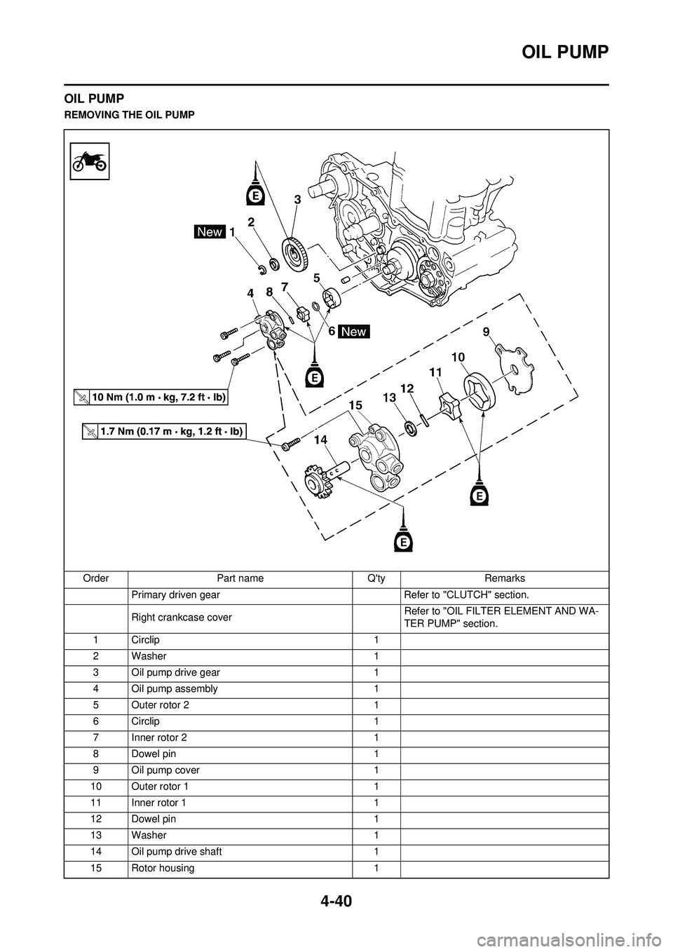
OIL PUMP
OIL PUMP
REMOVING THE OIL PUMPOrder Part name Q'ty Remarks Primary driven gear Refer to "CLUTCH" section.
Right crankcase cover Refer to "OIL FILTER ELEMENT AND WA-
TER PUMP" section.
1 Circlip 1
2 Washer 1
3 Oil pump drive gear 1
4 Oil pump assembly 1
5 Outer rotor 2 1
6 Circlip 1
7 Inner rotor 2 1
8 Dowel pin 1
9 Oil pump cover 1
10 Outer rotor 1 1
11 Inner rotor 1 1
12 Dowel pin 1
13 Washer 1
14 Oil pump drive shaft 1
15 Rotor housing 1
Page 115 of 196
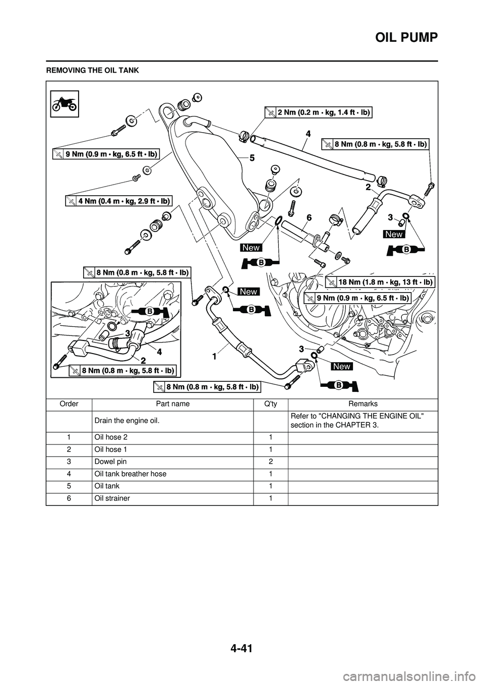
4-41
OIL PUMP
REMOVING THE OIL TANKOrder Part name Q'ty Remarks Drain the engine oil. Refer to "CHANGING THE ENGINE OIL"
section in the CHAPTER 3.
1 Oil hose 2 1
2 Oil hose 1 1
3 Dowel pin 2
4 Oil tank breather hose 1
5 Oil tank 1
6 Oil strainer 1
Page 116 of 196
4-42
OIL PUMP
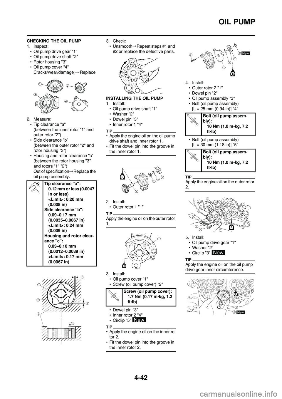
CHECKING THE OIL PUMP
1. Inspect:• Oil pump drive gear "1"
• Oil pump drive shaft "2"
• Rotor housing "3"
• Oil pump cover "4"Cracks/wear/damage →Replace.
2. Measure: • Tip clearance "a"(between the inner rotor "1" and
outer rotor "2")
• Side clearance "b" (between the outer rotor "2" and
rotor housing "3")
• Housing and rotor clearance "c" (between the rotor housing "3"
and rotors "1" "2")
Out of specification →Replace the
oil pump assembly. 3. Check:
• Unsmooth →Repeat steps #1 and
#2 or replace the defective parts.
INSTALLING THE OIL PUMP
1. Install: • Oil pump drive shaft "1"
• Washer "2"
• Dowel pin "3"
• Inner rotor 1 "4"
• Apply the engine oil on the oil pump drive shaft and inner rotor 1.
• Fit the dowel pin into the groove in
the inner rotor 1.
2. Install:• Outer rotor 1 "1"
Apply the engine oil on the outer rotor
1.
3. Install:• Oil pump cover "1"
• Screw (oil pump cover) "2"
• Dowel pin "3"
• Inner rotor 2 "4"
• Circlip "5"
• Apply the engine oil on the inner ro-tor 2.
• Fit the dowel pin into the groove in
the inner rotor 2.
4. Install:• Outer rotor 2 "1"
• Dowel pin "2"
• Oil pump assembly "3"
• Bolt (oil pump assembly)
[L = 25 mm (0.94 in)] "4"
• Bolt (oil pump assembly) [L = 30 mm (1.18 in)] "5"
Apply the engine oil on the outer rotor
2.
5. Install:
• Oil pump drive gear "1"
• Washer "2"
• Circlip "3"
Apply the engine oil on the oil pump
drive gear inner circumference.
Tip clearance "a": 0.12 mm or less (0.0047
in or less)
(0.008 in)
Side clearance "b": 0.09–0.17 mm
(0.0035–0.0067 in)
(0.009 in)
Housing and rotor clear-
ance "c": 0.03–0.10 mm
(0.0012–0.0039 in)
(0.0067 in)
Screw (oil pump cover):1.7 Nm (0.17 m•kg, 1.2
ft•lb)
Bolt (oil pump assem-
bly): 10 Nm (1.0 m•kg, 7.2
ft•lb)
Bolt (oil pump assem-
bly): 10 Nm (1.0 m•kg, 7.2
ft•lb)
Page 117 of 196
4-43
OIL PUMP
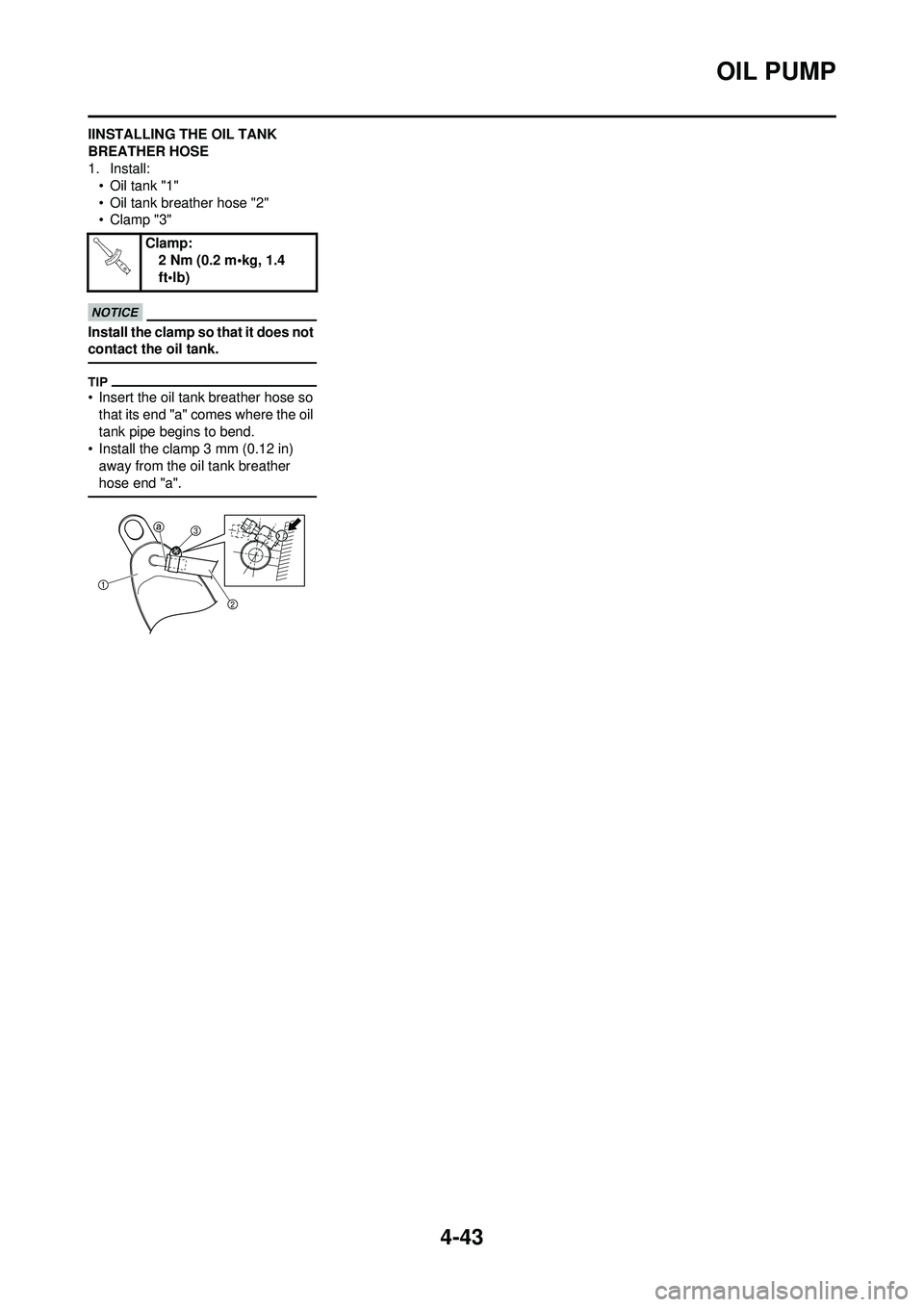
IINSTALLING THE OIL TANK
BREATHER HOSE
1. Install:• Oil tank "1"
• Oil tank breather hose "2"
• Clamp "3"
Install the clamp so that it does not
contact the oil tank.
• Insert the oil tank breather hose so
that its end "a" comes where the oil
tank pipe begins to bend.
• Install the clamp 3 mm (0.12 in)
away from the oil tank breather
hose end "a".
Clamp: 2 Nm (0.2 m•kg, 1.4
ft•lb)
Page 118 of 196
4-44
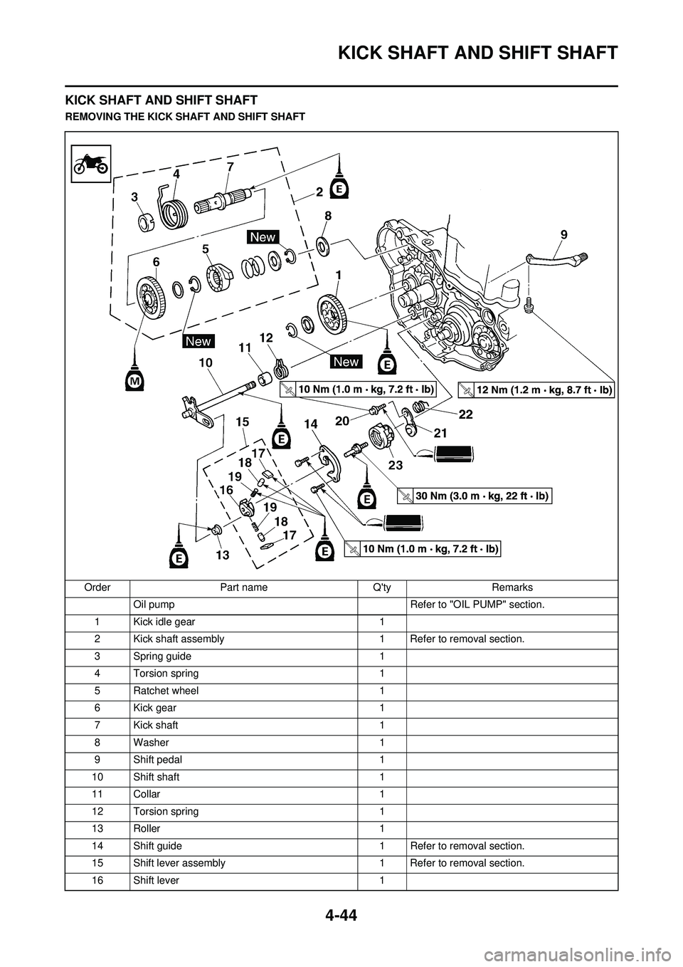
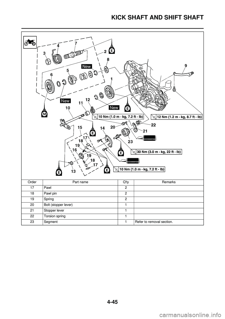
KICK SHAFT AND SHIFT SHAFT
KICK SHAFT AND SHIFT SHAFT
REMOVING THE KICK SHAFT AND SHIFT SHAFTOrder Part name Q'ty Remarks Oil pump Refer to "OIL PUMP" section.
1 Kick idle gear 1
2 Kick shaft assembly 1 Refer to removal section.
3 Spring guide 1
4 Torsion spring 1
5 Ratchet wheel 1
6 Kick gear 1
7 Kick shaft 1
8 Washer 1
9 Shift pedal 1
10 Shift shaft 1
11 Collar 1
12 Torsion spring 1
13 Roller 1
14 Shift guide 1 Refer to removal section.
15 Shift lever assembly 1 Refer to removal section.
16 Shift lever 1
Page 119 of 196
4-45
KICK SHAFT AND SHIFT SHAFT
17 Pawl2
18 Pawl pin 2
19 Spring 2
20 Bolt (stopper lever) 1
21 Stopper lever 1
22 Torsion spring 1
23 Segment 1 Refer to removal section.
Order
Part name Q'tyRemarks
Page 120 of 196
4-46
KICK SHAFT AND SHIFT SHAFT
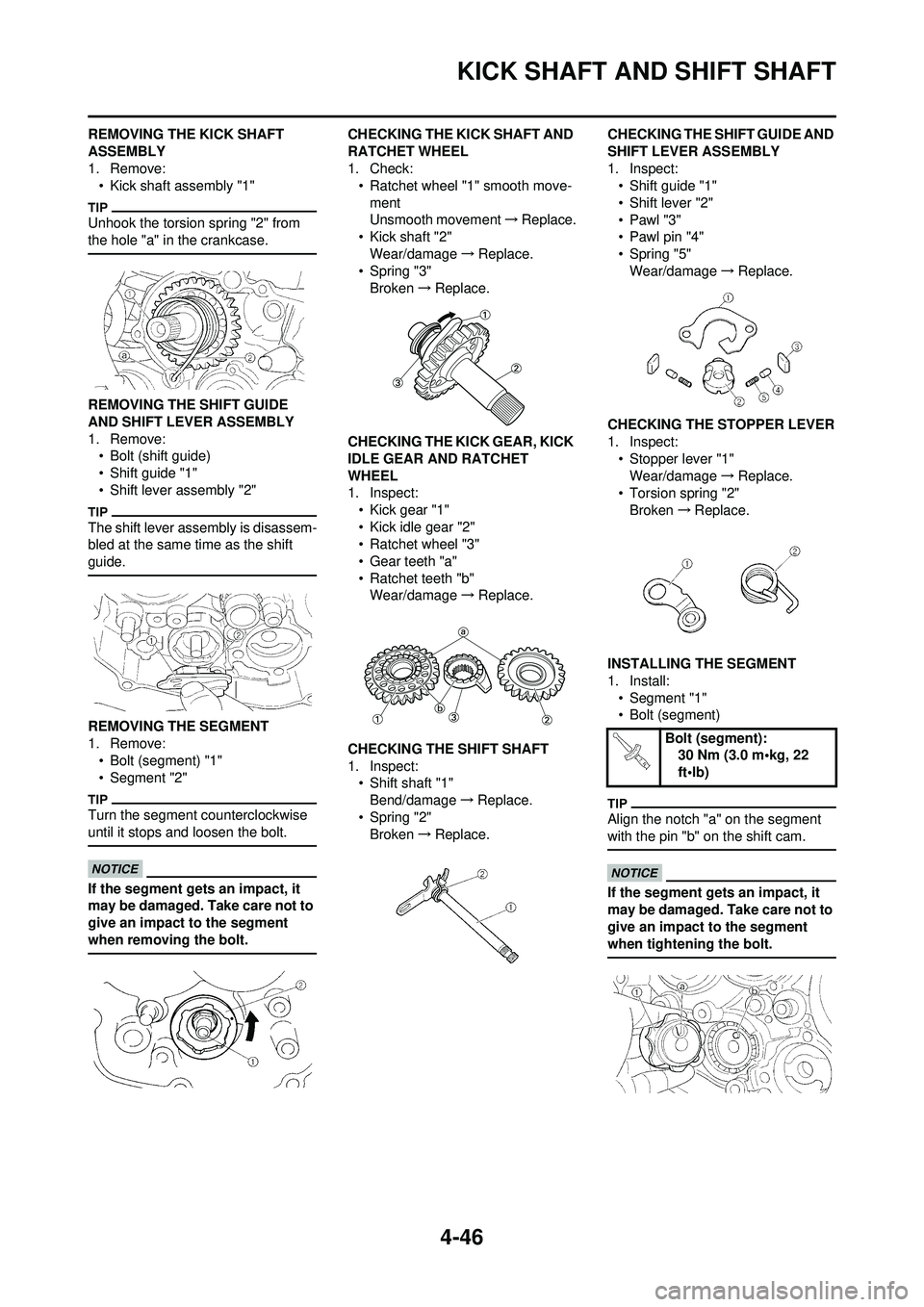
REMOVING THE KICK SHAFT
ASSEMBLY
1. Remove:• Kick shaft assembly "1"
Unhook the torsion spring "2" from
the hole "a" in the crankcase.
REMOVING THE SHIFT GUIDE
AND SHIFT LEVER ASSEMBLY
1. Remove:• Bolt (shift guide)
• Shift guide "1"
• Shift lever assembly "2"
The shift lever assembly is disassem-
bled at the same time as the shift
guide.
REMOVING THE SEGMENT
1. Remove:
• Bolt (segment) "1"
• Segment "2"
Turn the segment counterclockwise
until it stops and loosen the bolt.
If the segment gets an impact, it
may be damaged. Take care not to
give an impact to the segment
when removing the bolt.
CHECKING THE KICK SHAFT AND
RATCHET WHEEL
1. Check:• Ratchet wheel "1" smooth move-
ment
Unsmooth movement →Replace.
• Kick shaft "2"
Wear/damage →Replace.
• Spring "3" Broken →Replace.
CHECKING THE KICK GEAR, KICK
IDLE GEAR AND RATCHET
WHEEL
1. Inspect: • Kick gear "1"
• Kick idle gear "2"
• Ratchet wheel "3"
• Gear teeth "a"
• Ratchet teeth "b"Wear/damage →Replace.
CHECKING THE SHIFT SHAFT
1. Inspect: • Shift shaft "1"
Bend/damage →Replace.
• Spring "2" Broken →Replace. CHECKING THE SHIFT GUIDE AND
SHIFT LEVER ASSEMBLY
1. Inspect:
• Shift guide "1"
• Shift lever "2"
•Pawl "3"
• Pawl pin "4"
• Spring "5"Wear/damage →Replace.
CHECKING THE STOPPER LEVER
1. Inspect: • Stopper lever "1"Wear/damage →Replace.
• Torsion spring "2"
Broken →Replace.
INSTALLING THE SEGMENT
1. Install: • Segment "1"
• Bolt (segment)
Align the notch "a" on the segment
with the pin "b" on the shift cam.
If the segment gets an impact, it
may be damaged. Take care not to
give an impact to the segment
when tightening the bolt.
Bolt (segment): 30 Nm (3.0 m•kg, 22
ft•lb)