YAMAHA YZ250F 2015 Service Manual
Manufacturer: YAMAHA, Model Year: 2015, Model line: YZ250F, Model: YAMAHA YZ250F 2015Pages: 356, PDF Size: 11.39 MB
Page 41 of 356
CLEANING AND STORAGE
1-27
EAS1SM5050
CLEANING AND STORAGE
EAS1SM5051CLEANING
Frequent cleaning of your vehicle will enhance
its appearance, maintain performance, and ex-
tend the life of parts.
1. Before cleaning, block the silencer outlet to
prevent water from entering. A plastic bag
secured with a rubber band may be used for
this purpose.
2. If the engine is contaminated with oil, apply
some degreaser to it with a brush. Do not
apply degreaser to the drive chain, the
sprockets, or the wheel axles.
3. Hose off dirt. Use only enough water pres-
sure to do the job.
ECA
NOTICE
Do not use high-pressure washers or steam
cleaners. Otherwise, these may cause a fail-
ure because of the entry of water.
4. After hosing off the dirt, wash all surfaces
with a mild detergent and warm water. Use
a toothbrush to clean hard-to-reach places.
5. Rinse the detergent with clean water, and
dry the surfaces with a soft towel or a cloth.
6. Immediately after cleaning, remove any wa-
ter from the drive chain with a paper towel,
and lubricate it to prevent rust.
7. Clean the seat with a vinyl upholstery clean-
er to keep the cover pliable and glossy.
8. Automotive wax may be applied to all paint-
ed or chromed surfaces. Avoid using such
wax as contains abrasives, because it may
scratch surfaces.
9. After completing the above, start the engine
and allow it to warm up for several minutes.
EAS1SM5052STORAGE
If your vehicle is to be stored for 60 days or
more, some preventive measures must be tak-
en to avoid deterioration. After cleaning the ve-
hicle thoroughly, prepare it for storage as
follows:
1. Fill the fuel tank with gasoline.
2. Remove the spark plug, pour a spoonful of
engine oil (SAE 10W-40) into the spark plug
hole, and reinstall the plug. With the engine
stop switch pushed in, by pushing down the
kickstarter lever, crank the engine to coat
the cylinder walls with oil.3. Remove the drive chain, clean it thoroughly
with solvent, and lubricate it Reinstall the
drive chain or store it in a plastic bag tied to
the frame.
4. Lubricate all cables.
5. Lift up the frame of the vehicle to keep the
wheels off the ground.
6. Tie a plastic bag over the muffler outlet to
prevent moisture from entering.
7. If the vehicle is to be stored in a place that is
humid or exposed to the sea breeze, apply a
light coat of oil to metal surfaces. Do not ap-
ply oil to the seat or rubber parts.
TIP
Make any necessary repairs before the vehicle
is stored.
Page 42 of 356

CLEANING AND STORAGE
1-28
Page 43 of 356

2
SPECIFICATIONS
GENERAL SPECIFICATIONS......................................................................... 2-1
ENGINE SPECIFICATIONS............................................................................. 2-2
CHASSIS SPECIFICATIONS........................................................................... 2-8
ELECTRICAL SPECIFICATIONS.................................................................. 2-11
TIGHTENING TORQUES............................................................................... 2-12
GENERAL TIGHTENING TORQUE SPECIFICATIONS .......................... 2-12
ENGINE TIGHTENING TORQUES .......................................................... 2-13
CHASSIS TIGHTENING TORQUES ........................................................ 2-16
LUBRICATION POINTS AND LUBRICANT TYPES..................................... 2-19
ENGINE .................................................................................................... 2-19
CHASSIS .................................................................................................. 2-21
LUBRICATION SYSTEM CHART AND DIAGRAMS..................................... 2-23
LUBRICATION DIAGRAMS ..................................................................... 2-23
CABLE ROUTING DIAGRAM........................................................................ 2-31
Page 44 of 356

GENERAL SPECIFICATIONS
2-1
EAS1SM5053
GENERAL SPECIFICATIONS
Model
Model 1SM5 (USA) (CAN)
1SM6 (EUR)
1SM7 (JPN)
1SM8 (AUS) (NZL) (ZAF)
Dimensions
Overall length 2165 mm (85.2 in) (USA) (CAN) (AUS) (NZL)
(ZAF)
2170 mm (85.4 in) (EUR) (JPN)
Overall width 825 mm (32.5 in)
Overall height 1280 mm (50.4 in) (USA) (CAN) (EUR) (JPN)
1275 mm (50.2 in) (AUS) (NZL) (ZAF)
Seat height 965 mm (38.0 in) (USA) (CAN) (EUR) (JPN)
960 mm (37.8 in) (AUS) (NZL) (ZAF)
Wheelbase 1475 mm (58.1 in)
Ground clearance 325 mm (12.8 in) (USA) (CAN) (AUS) (NZL)
(ZAF)
330 mm (13.0 in) (EUR) (JPN)
Weight
Curb weight 105 kg (231 lb)
Page 45 of 356

ENGINE SPECIFICATIONS
2-2
EAS1SM5054
ENGINE SPECIFICATIONS
Engine
Engine type Liquid cooled 4-stroke, DOHC
Displacement 250 cm
3
Cylinder arrangement Single cylinder
Bore stroke 77.0 53.6 mm (3.0 2.1 in)
Compression ratio 13.5:1
Starting system Kickstarter
Fuel
Recommended fuel Premium unleaded gasoline only
Fuel tank capacity 7.5 L (1.98 US gal, 1.65 Imp.gal)
Engine oil
Lubrication system Wet sump
Recommended brand YAMALUBE
Type SAE 10W-30, SAE 10W-40, SAE 10W-50,
SAE 15W-40, SAE 20W-40 or SAE 20W-50
Recommended oil grade API service SG type or higher, JASO standard
MA
Engine oil quantity
Quantity (disassembled) 0.90 L (0.95 US qt, 0.79 Imp.qt)
With oil filter element replacement 0.73 L (0.77 US qt, 0.64 Imp.qt)
Without oil filter element replacement 0.71 L (0.75 US qt, 0.62 Imp.qt)
Oil filter
Oil filter type Paper
Oil pump
Oil pump type Trochoid
Inner-rotor-to-outer-rotor-tip clearance Less than 0.150 mm (0.0059 in)
Limit 0.20 mm (0.0079 in)
Outer-rotor-to-oil-pump-housing clearance 0.13–0.18 mm (0.0051–0.0071 in)
Limit 0.24 mm (0.0094 in)
Oil-pump-housing-to-inner-and-outer-rotor
clearance 0.06–0.11 mm (0.0024–0.0043 in)
Limit 0.17 mm (0.0067 in)
Cooling system
Radiator capacity (including all routes) 1.00 L (1.06 US qt, 0.88 Imp.qt)
Radiator capacity 0.58 L (0.61 US qt, 0.51 Imp.qt)
Radiator cap opening pressure 108–137 kPa (1.08–1.37 kg/cm
2, 15.7–19.9
psi)
Radiator core
Width 112.6 mm (4.43 in)
Height 235.0 mm (9.25 in)
Depth 28.0 mm (1.10 in)
Water pump
Water pump type Single suction centrifugal pump
Spark plug
Manufacturer/model NGK/LMAR8G
Spark plug gap 0.7–0.8 mm (0.028–0.031 in)
Page 46 of 356
ENGINE SPECIFICATIONS
2-3
Cylinder head
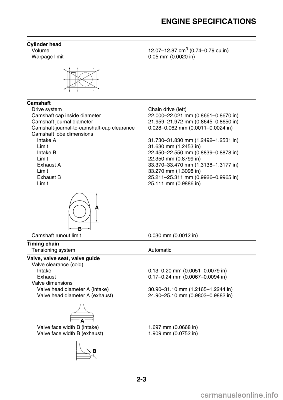
Volume 12.07–12.87 cm3 (0.74–0.79 cu.in)
Warpage limit 0.05 mm (0.0020 in)
Camshaft
Drive system Chain drive (left)
Camshaft cap inside diameter 22.000–22.021 mm (0.8661–0.8670 in)
Camshaft journal diameter 21.959–21.972 mm (0.8645–0.8650 in)
Camshaft-journal-to-camshaft-cap clearance 0.028–0.062 mm (0.0011–0.0024 in)
Camshaft lobe dimensions
Intake A 31.730–31.830 mm (1.2492–1.2531 in)
Limit 31.630 mm (1.2453 in)
Intake B 22.450–22.550 mm (0.8839–0.8878 in)
Limit 22.350 mm (0.8799 in)
Exhaust A 33.370–33.470 mm (1.3138–1.3177 in)
Limit 33.270 mm (1.3098 in)
Exhaust B 25.211–25.311 mm (0.9926–0.9965 in)
Limit 25.111 mm (0.9886 in)
Camshaft runout limit 0.030 mm (0.0012 in)
Timing chain
Tensioning system Automatic
Valve, valve seat, valve guide
Valve clearance (cold)
Intake 0.13–0.20 mm (0.0051–0.0079 in)
Exhaust 0.17–0.24 mm (0.0067–0.0094 in)
Valve dimensions
Valve head diameter A (intake) 30.90–31.10 mm (1.2165–1.2244 in)
Valve head diameter A (exhaust) 24.90–25.10 mm (0.9803–0.9882 in)
Valve face width B (intake) 1.697 mm (0.0668 in)
Valve face width B (exhaust) 1.909 mm (0.0752 in)
A
B
A
B
Page 47 of 356
ENGINE SPECIFICATIONS
2-4
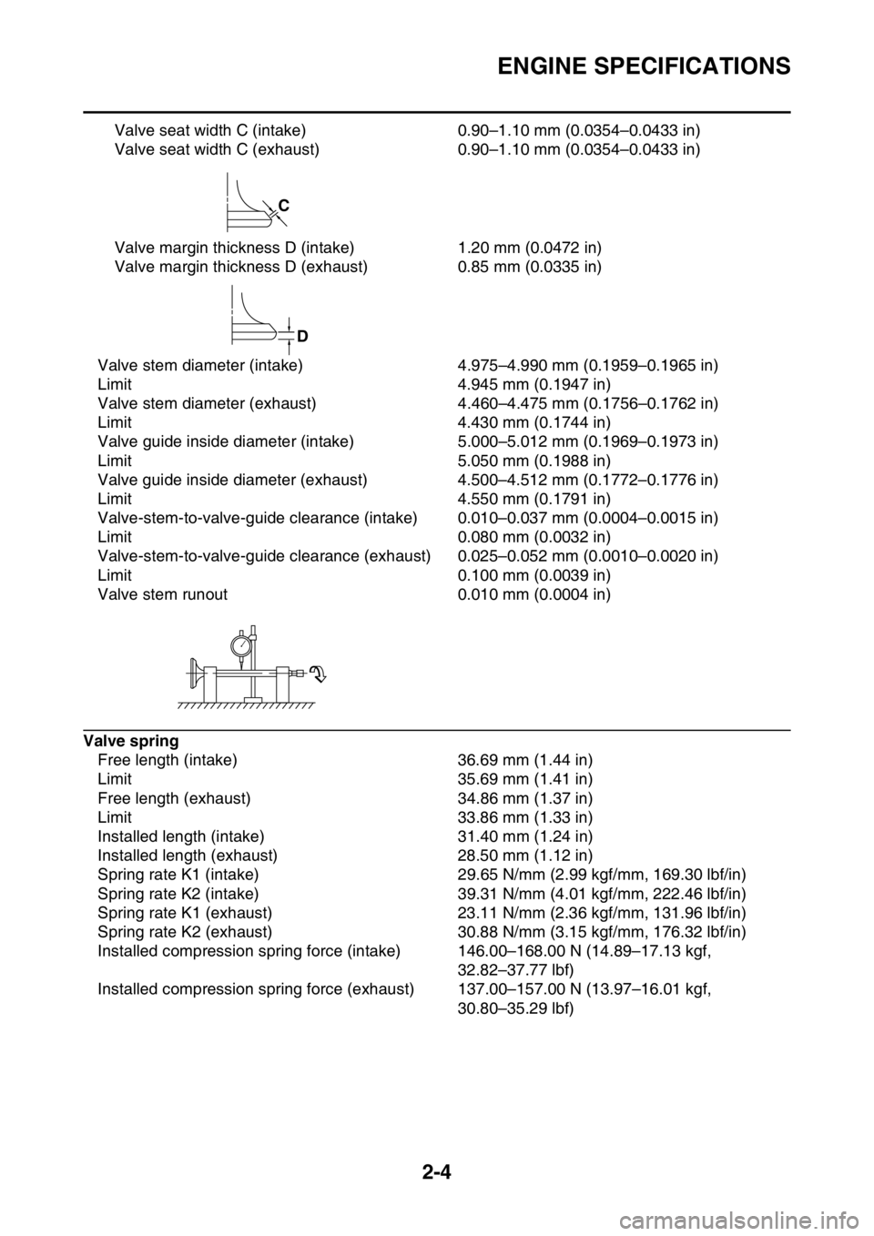
Valve seat width C (intake) 0.90–1.10 mm (0.0354–0.0433 in)
Valve seat width C (exhaust) 0.90–1.10 mm (0.0354–0.0433 in)
Valve margin thickness D (intake) 1.20 mm (0.0472 in)
Valve margin thickness D (exhaust) 0.85 mm (0.0335 in)
Valve stem diameter (intake) 4.975–4.990 mm (0.1959–0.1965 in)
Limit 4.945 mm (0.1947 in)
Valve stem diameter (exhaust) 4.460–4.475 mm (0.1756–0.1762 in)
Limit 4.430 mm (0.1744 in)
Valve guide inside diameter (intake) 5.000–5.012 mm (0.1969–0.1973 in)
Limit 5.050 mm (0.1988 in)
Valve guide inside diameter (exhaust) 4.500–4.512 mm (0.1772–0.1776 in)
Limit 4.550 mm (0.1791 in)
Valve-stem-to-valve-guide clearance (intake) 0.010–0.037 mm (0.0004–0.0015 in)
Limit 0.080 mm (0.0032 in)
Valve-stem-to-valve-guide clearance (exhaust) 0.025–0.052 mm (0.0010–0.0020 in)
Limit 0.100 mm (0.0039 in)
Valve stem runout 0.010 mm (0.0004 in)
Valve spring
Free length (intake) 36.69 mm (1.44 in)
Limit 35.69 mm (1.41 in)
Free length (exhaust) 34.86 mm (1.37 in)
Limit 33.86 mm (1.33 in)
Installed length (intake) 31.40 mm (1.24 in)
Installed length (exhaust) 28.50 mm (1.12 in)
Spring rate K1 (intake) 29.65 N/mm (2.99 kgf/mm, 169.30 lbf/in)
Spring rate K2 (intake) 39.31 N/mm (4.01 kgf/mm, 222.46 lbf/in)
Spring rate K1 (exhaust) 23.11 N/mm (2.36 kgf/mm, 131.96 lbf/in)
Spring rate K2 (exhaust) 30.88 N/mm (3.15 kgf/mm, 176.32 lbf/in)
Installed compression spring force (intake) 146.00–168.00 N (14.89–17.13 kgf,
32.82–37.77 lbf)
Installed compression spring force (exhaust) 137.00–157.00 N (13.97–16.01 kgf,
30.80–35.29 lbf)
C
D
Page 48 of 356
ENGINE SPECIFICATIONS
2-5
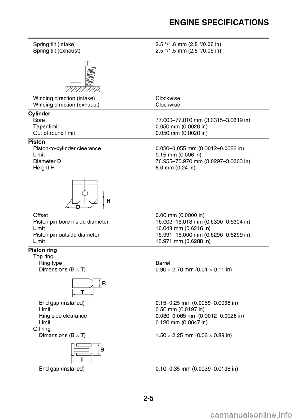
Spring tilt (intake) 2.5 °/1.6 mm (2.5 °/0.06 in)
Spring tilt (exhaust) 2.5 °/1.5 mm (2.5 °/0.06 in)
Winding direction (intake) Clockwise
Winding direction (exhaust) Clockwise
Cylinder
Bore 77.000–77.010 mm (3.0315–3.0319 in)
Taper limit 0.050 mm (0.0020 in)
Out of round limit 0.050 mm (0.0020 in)
Piston
Piston-to-cylinder clearance 0.030–0.055 mm (0.0012–0.0022 in)
Limit 0.15 mm (0.006 in)
Diameter D 76.955–76.970 mm (3.0297–3.0303 in)
Height H 6.0 mm (0.24 in)
Offset 0.00 mm (0.0000 in)
Piston pin bore inside diameter 16.002–16.013 mm (0.6300–0.6304 in)
Limit 16.043 mm (0.6316 in)
Piston pin outside diameter 15.991–16.000 mm (0.6296–0.6299 in)
Limit 15.971 mm (0.6288 in)
Piston ring
Top ring
Ring type Barrel
Dimensions (B T) 0.90 2.70 mm (0.04 0.11 in)
End gap (installed) 0.15–0.25 mm (0.0059–0.0098 in)
Limit 0.50 mm (0.0197 in)
Ring side clearance 0.030–0.065 mm (0.0012–0.0026 in)
Limit 0.120 mm (0.0047 in)
Oil ring
Dimensions (B T) 1.50 2.25 mm (0.06 0.89 in)
End gap (installed) 0.10–0.35 mm (0.0039–0.0138 in)
H
D
T
B
B
T
Page 49 of 356
ENGINE SPECIFICATIONS
2-6
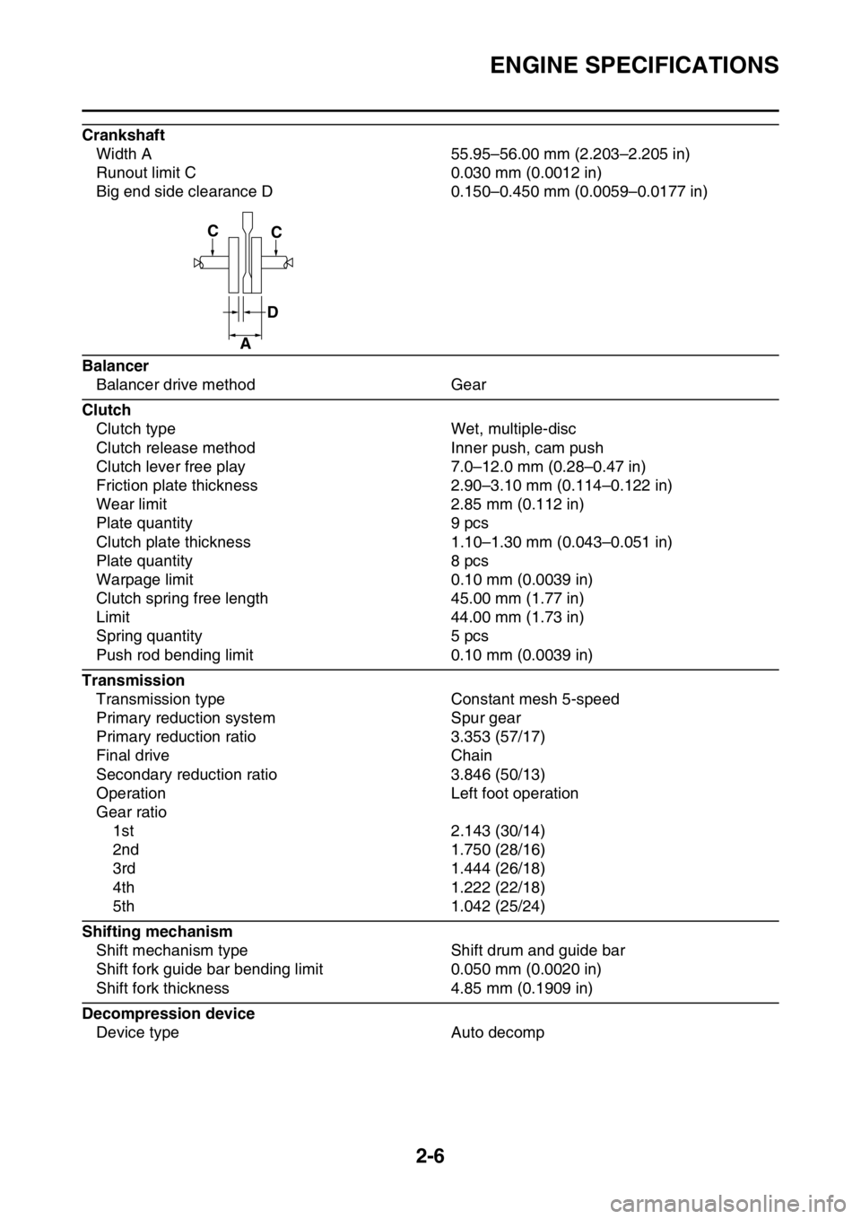
Crankshaft
Width A 55.95–56.00 mm (2.203–2.205 in)
Runout limit C 0.030 mm (0.0012 in)
Big end side clearance D 0.150–0.450 mm (0.0059–0.0177 in)
Balancer
Balancer drive method Gear
Clutch
Clutch type Wet, multiple-disc
Clutch release method Inner push, cam push
Clutch lever free play 7.0–12.0 mm (0.28–0.47 in)
Friction plate thickness 2.90–3.10 mm (0.114–0.122 in)
Wear limit 2.85 mm (0.112 in)
Plate quantity 9 pcs
Clutch plate thickness 1.10–1.30 mm (0.043–0.051 in)
Plate quantity 8 pcs
Warpage limit 0.10 mm (0.0039 in)
Clutch spring free length 45.00 mm (1.77 in)
Limit 44.00 mm (1.73 in)
Spring quantity 5 pcs
Push rod bending limit 0.10 mm (0.0039 in)
Transmission
Transmission type Constant mesh 5-speed
Primary reduction system Spur gear
Primary reduction ratio 3.353 (57/17)
Final drive Chain
Secondary reduction ratio 3.846 (50/13)
Operation Left foot operation
Gear ratio
1st 2.143 (30/14)
2nd 1.750 (28/16)
3rd 1.444 (26/18)
4th 1.222 (22/18)
5th 1.042 (25/24)
Shifting mechanism
Shift mechanism type Shift drum and guide bar
Shift fork guide bar bending limit 0.050 mm (0.0020 in)
Shift fork thickness 4.85 mm (0.1909 in)
Decompression device
Device type Auto decomp
CC
D
A
Page 50 of 356

ENGINE SPECIFICATIONS
2-7
Air filter
Air filter element Wet element
Air filter oil grade Foam air-filter oil
Fuel pump
Pump type Electrical
Fuel injector
Model/quantity 30NA-FZ31/1
Resistance 12
Throttle body
Type/quantity 30RA-A71S/1
ID mark 1SM5 10
Fuel pressure 324.0 kPa (3.24 kgf/cm
2, 47.0 psi)
Throttle position sensor
Resistance 6.30 k
Output voltage (at idle) 0.5 V
Fuel injection sensor
Crankshaft position sensor resistance 228–342
Intake air pressure sensor output voltage 3.57–3.71 V at 101.3 kPa
Intake air temperature sensor resistance 290–390 at 80 °C (176 °F)
Coolant temperature sensor resistance 2.51–2.78 k at 20 °C (68 °F)
210–221 at 100 °C (212 °F)
Idling condition
Engine idling speed 1900–2100 r/min
Water temperature 70–80 °C (158–176 °F)
Oil temperature 55–65 °C (131–149 °F)
Throttle grip free play 3.0–5.0 mm (0.12–0.20 in)