YAMAHA YZ250F 2015 Manual PDF
YZ250F 2015
YAMAHA
YAMAHA
https://www.carmanualsonline.info/img/51/53925/w960_53925-0.png
YAMAHA YZ250F 2015 Manual PDF
Trending: engine overheat, coolant temperature, diagram, oil additives, ABS, oil temperature, ignition
Page 71 of 356
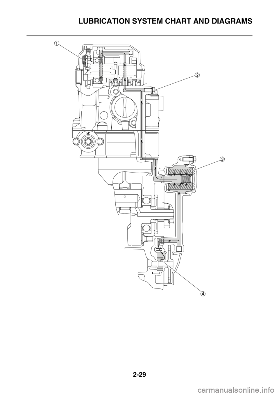
LUBRICATION SYSTEM CHART AND DIAGRAMS
2-28
1. Exhaust camshaft
2. Intake camshaft
3. Oil filter element
4. Oil pump
Page 72 of 356
LUBRICATION SYSTEM CHART AND DIAGRAMS
2-29
Page 73 of 356
LUBRICATION SYSTEM CHART AND DIAGRAMS
2-30
1. Camshaft
2. Oil pressure check bolt
3. Oil filter element
4. Oil pump
Page 74 of 356
CABLE ROUTING DIAGRAM
2-31
EAS1SM5065
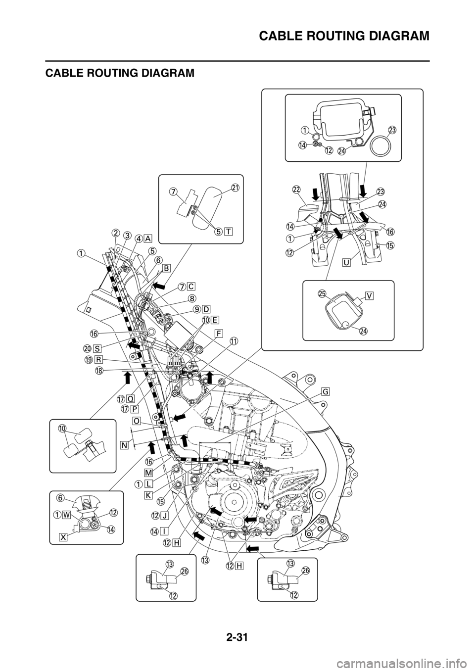
CABLE ROUTING DIAGRAM
Page 75 of 356

CABLE ROUTING DIAGRAM
2-32
1. Clutch cable
2. Throttle cable (pull)
3. Throttle cable (return)
4. Cable holder
5. Engine stop switch lead
6. Frame
7. Coupler for connecting optional part
8. Bracket
9. Engine stop switch coupler
10. Rectifier/regulator coupler
11. Starter knob/idle screw
12. Neutral switch lead
13. Crankcase cover
14. AC magneto lead
15. Front engine bracket
16. Radiator hose
17. Coupler cover
18. Tension arm
19. Rectifier/regulator lead
20. Main harness
21. Tank rail
22. Radiator
23. Cylinder head breather hose
24. Radiator breather hose
25. Down tube
26. Crankcase
A. Pass the engine stop switch lead between the
frame and the cable holder.
B. Pass the engine stop switch lead between the
coupler for connecting optional part and the
frame, where the main harness should face the
outside of the vehicle.
C. Insert the coupler for connecting optional part into
the connector, and fix it to the bracket.
D. Insert and fix the engine stop switch coupler to
the bracket.
E. Insert and fix the rectifier/regulator coupler to the
bracket.
F. Pass the AC magneto lead to the front of the ve-
hicle beyond the starter knob/idle screw and to
the rear of the vehicle beyond the radiator. No
pinch is allowed between the radiator and the
tension arm.
G. 70 mm (2.76 in)
H. Bring the neutral switch lead into line with the
crankcase cover with no sag allowed.
I. Bring the AC magneto lead into line with the
clutch cable with no sag allowed.
J. Pass the neutral switch lead to the inside of the
front engine bracket (the side of the vehicle).
K. Clamp the clutch cable and the AC magneto lead
by the plastic locking tie. Regardless of the orien-
tation of the lock on the plastic locking tie, cut the
end.
L. Pass the clutch cable with no downward sag al-
lowed.
M. Bring the grommet of the clutch cable into contact
with the radiator hose, and pass it to the outside
of the neutral switch lead and the AC magneto
lead (the outside of the vehicle).
N. 40 mm (1.57 in)
O. Clamp the clutch cable, the AC magneto lead,
and the neutral switch lead by the plastic locking
tie. Make sure that they are clamped at the posi-
tioning tape in the clutch cable. Make the lock on
the plastic locking tie face the front of the vehicle,
and cut the end.
P. After connecting the neutral switch coupler, at-
tach the coupler cover.
Q. After connecting the AC magneto coupler, attach
the coupler cover.R. Pass the rectifier/regulator lead to the inside of
the tension arm (the side of the vehicle).
S. Pass the main harness to the front of the radiator
hose (the front of the vehicle), and to the inside of
the clutch cable (the side of the vehicle).
T. Pass the engine stop switch lead between the
coupler for connecting optional part and the tank
rail, with the lead on the main harness side facing
the top of the vehicle.
U. Pass the radiator breather hose between the
down tubes.
V. Clamp the radiator breather hose, above the en-
gine bracket (front). Clamp the lock on the plastic
tie with it located outside the vehicle, and face the
end toward the front of the vehicle.
W. Clamp the clutch cable at the front of the lead (the
front of the vehicle).
X. Make the lock on the plastic locking tie face the
front of the vehicle, and insert the projection into
the hole in the frame. Cut the end of the plastic
locking tie.
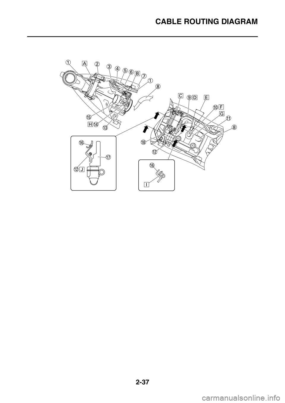
Page 76 of 356
CABLE ROUTING DIAGRAM
2-33
Page 77 of 356

CABLE ROUTING DIAGRAM
2-34
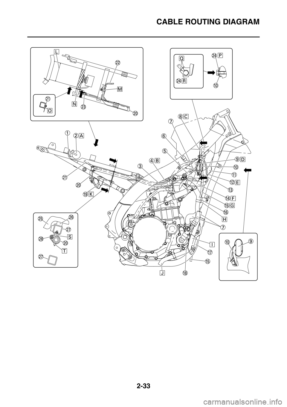
1. Bracket
2. Condenser
3. Coolant temperature sensor
4. Coupler cover
5. Intake air temperature sensor coupler
6. Intake air temperature sensor coupler
7. Radiator hoses
8. Radiator breather hose
9. Joint coupler
10. Plate
11. Tension arm
12. Throttle position sensor lead
13. Ground lead
14. Throttle position sensor coupler
15. Radiator breather hose
16. Cylinder head breather hose
17. Engine guard
18. Crankcase
19. Fuel pump coupler
20. Fuel hose
21. Condenser lead
22. Fuel pump lead
23. Condenser coupler
24. Ground lead terminal
25. Fuel tank
26. Damper
27. Rear frame
28. Main harness
A. Insert the condenser into the bracket as far as it
will go.
B. Attach the coupler cover to the coolant tempera-
ture sensor coupler.
C. Pass the radiator breather hose to the inside of
the radiator hose (the side of the vehicle).
D. Insert and fix the joint coupler to the plate. After
fixing it, attach the cover.
E. Pass the throttle position sensor lead to the out-
side of the tension arm (the outside of the vehi-
cle).
F. After connecting the throttle position sensor cou-
pler, attach the cover.
G. Pass the radiator breather hose to the outside of
the tension arm and the throttle position sensor
lead (the outside of the vehicle), and to the inside
of the radiator hose (the side of the vehicle).
H. Pass the protector of the cylinder head breather
hose until it touches the holder.
I. Pass the cylinder head breather hose between
the engine guard and the crankcase.
J. Install the end of the cylinder head breather hose
with it facing downward.
K. After connecting the fuel pump coupler, attach
the coupler cover.
L. 55 mm (2.17 in) (seat load receiver)
M. Clamp the fuel hose and the fuel pump lead by
the holder. Make sure that the painted part on the
fuel hose is clamped, and face the lock on the
clamp toward the rear top of the vehicle.
N. Do not install the plastic locking tie to the seat
load receiver.
O. Make the lock on the plastic locking tie face the
front of the vehicle, and make the end face the
bottom of the vehicle. Do not cut the end.
P. Install the ground lead terminal between the plate
and the bolt.
Q. Detent
R. Fix the ground lead terminal to the detent in the
plate. For the ground lead terminal, either side
will do.S. Insert the projection on the plastic locking tie into
the hole in the rear frame.
T. Clamp the painted part on the fuel hose by the
plastic clamp. Make the lock on the plastic clamp
face the bottom of the vehicle, and cut the end.
Page 78 of 356
CABLE ROUTING DIAGRAM
2-35
Page 79 of 356
CABLE ROUTING DIAGRAM
2-36
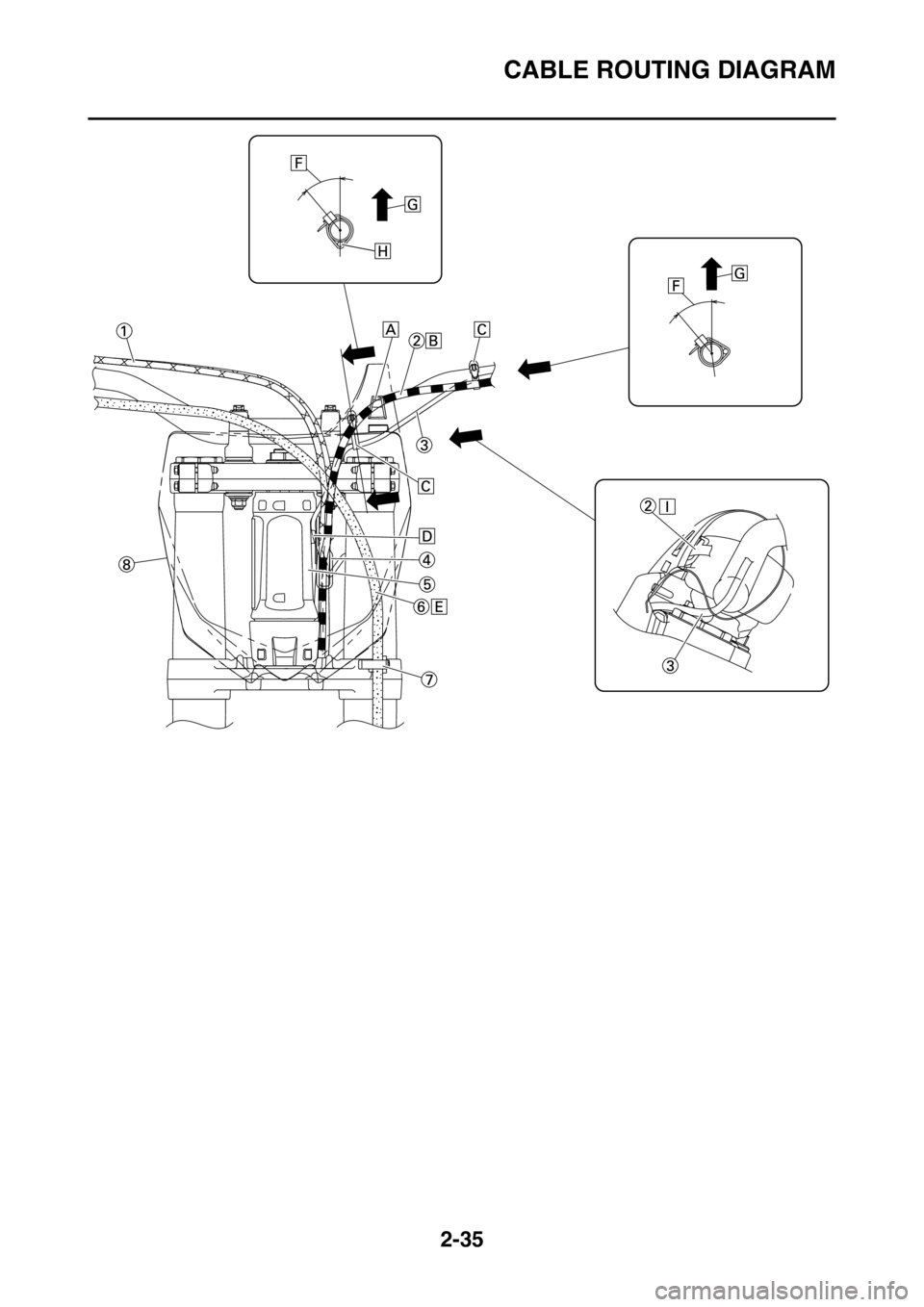
1. Throttle cable
2. Clutch cable
3. Engine stop switch lead
4. Cable guide
5. Head pipe
6. Front brake hose
7. Brake hose guide
8. Number plate
A. Number plate band
B. Pass the clutch cable to the rear of the number
plate band.
C. Clamp the engine stop switch lead to the handle-
bar by the plastic band. Do not cut the end of the
plastic band.
D. Pass the engine stop switch lead between the
head pipe and the cable guide.
E. Pass the front brake hose to the front of the num-
ber plate.
F. 40°±10°
G. Vertical direction
H. Pass the engine stop switch lead under the han-
dlebar.
I. Pass the clutch cable to the guide in the number
plate.
Page 80 of 356
CABLE ROUTING DIAGRAM
2-37
Trending: length, open gas tank, AUX, turn signal, fuel filter, fuel pressure, stop start

