lock YAMAHA YZ450F 2006 Notices Demploi (in French)
[x] Cancel search | Manufacturer: YAMAHA, Model Year: 2006, Model line: YZ450F, Model: YAMAHA YZ450F 2006Pages: 650, PDF Size: 20.71 MB
Page 595 of 650

–+ELEC
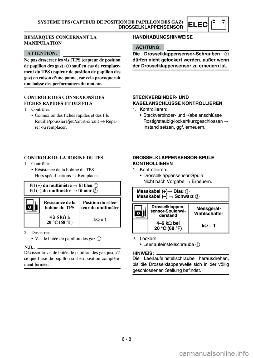
HANDHABUNGSHINWEISE
ACHTUNG:
Die Drosselklappensensor-Schrauben 1
dürfen nicht gelockert werden, außer wenn
der Drosselklappensensor zu erneuern ist.
STECKVERBINDER- UND
KABELANSCHLÜSSE KONTROLLIEREN
1. Kontrollieren:
Steckverbinder- und Kabelanschlüsse
Rostig/staubig/locker/kurzgeschlossen →
Instand setzen, ggf. erneuern.
DROSSELKLAPPENSENSOR-SPULE
KONTROLLIEREN
1. Kontrollieren:
Drosselklappensensor-Spule
Nicht nach Vorgabe → Erneuern.
2. Lockern:
Leerlaufeinstellschraube 1
HINWEIS:
Die Leerlaufeinstellschraube herausdrehen,
bis die Drosselklappenwelle sich in der völlig
geschlossenen Stellung befindet.Messkabel (+)→ Blau 1
Messkabel (–) → Schwarz 2
Drosselklappen-
sensor-Spulenwi-
derstandMessgerät-
Wahlschalter
4–6 kΩ bei
20 °C (68 °F)kΩ × 1
SYSTEME TPS (CAPTEUR DE POSITION DE PAPILLON DES GAZ)
DROSSELKLAPPENSENSOR
REMARQUES CONCERNANT LA
MANIPULATION
ATTENTION:
Ne pas desserrer les vis {TPS (capteur de position
de papillon des gaz)} 1 sauf en cas de remplace-
ment du TPS (capteur de position de papillon des
gaz) en raison d’une panne, car cela provoquerait
une baisse des performances du moteur.
CONTROLE DES CONNEXIONS DES
FICHES RAPIDES ET DES FILS
1. Contrôler:
Connexion des fiches rapides et des fils
Rouille/poussière/jeu/court-circuit → Répa-
rer ou remplacer.
CONTROLE DE LA BOBINE DU TPS
1. Contrôler:
Résistance de la bobine du TPS
Hors spécifications → Remplacer.
2. Desserrer:
Vis de butée de papillon des gaz 1
N.B.:
Dévisser la vis de butée de papillon des gaz jusqu’à
ce que l’axe de papillon soit en position complète-
ment fermée. Fil (+) du multimètre → fil bleu 1
Fil (–) du multimètre → fil noir 2
Résistance de la
bobine du TPSPosition du sélec-
teur du multimètre
4 à 6 kΩ à
20 °C (68 °F)kΩ × 1
6 - 8
Page 597 of 650

–+ELEC
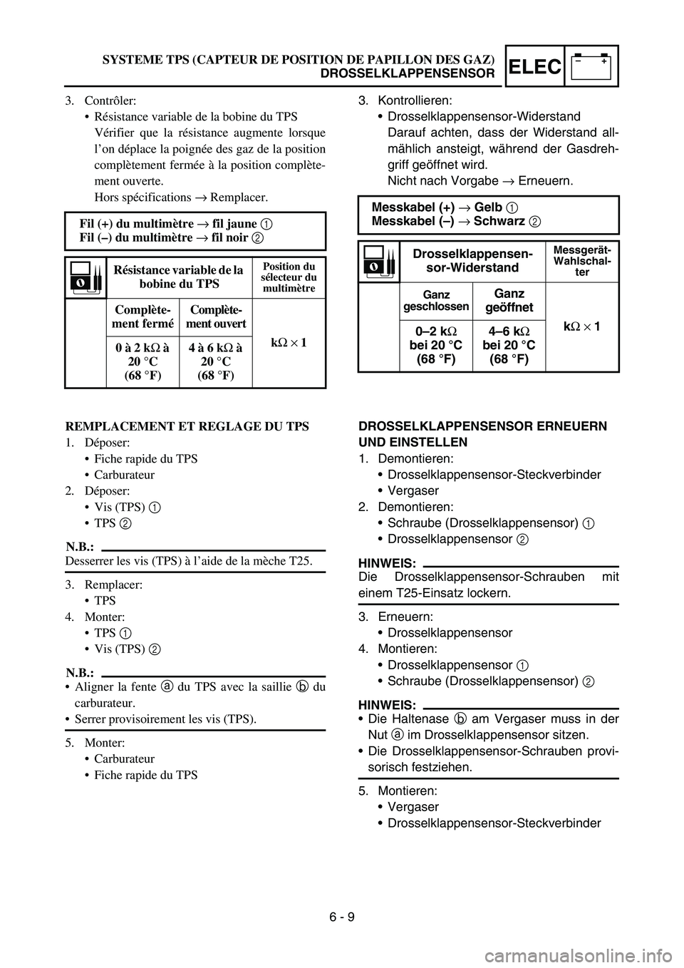
3. Kontrollieren:
Drosselklappensensor-Widerstand
Darauf achten, dass der Widerstand all-
mählich ansteigt, während der Gasdreh-
griff geöffnet wird.
Nicht nach Vorgabe → Erneuern.
Messkabel (+) → Gelb 1
Messkabel (–) → Schwarz 2
Drosselklappensen-
sor-WiderstandMessgerät-
Wahlschal-
ter
Ganz
geschlossenGanz
geöffnet
kΩ × 1
0–2 kΩ
bei 20 °C
(68°F)4–6 kΩ
bei 20 °C
(68°F)
DROSSELKLAPPENSENSOR ERNEUERN
UND EINSTELLEN
1. Demontieren:
Drosselklappensensor-Steckverbinder
Vergaser
2. Demontieren:
Schraube (Drosselklappensensor) 1
Drosselklappensensor 2
HINWEIS:
Die Drosselklappensensor-Schrauben mit
einem T25-Einsatz lockern.
3. Erneuern:
Drosselklappensensor
4. Montieren:
Drosselklappensensor 1
Schraube (Drosselklappensensor) 2
HINWEIS:
Die Haltenase b am Vergaser muss in der
Nut a im Drosselklappensensor sitzen.
Die Drosselklappensensor-Schrauben provi-
sorisch festziehen.
5. Montieren:
Vergaser
Drosselklappensensor-Steckverbinder SYSTEME TPS (CAPTEUR DE POSITION DE PAPILLON DES GAZ)
DROSSELKLAPPENSENSOR
3. Contrôler:
Résistance variable de la bobine du TPS
Vérifier que la résistance augmente lorsque
l’on déplace la poignée des gaz de la position
complètement fermée à la position complète-
ment ouverte.
Hors spécifications → Remplacer.
Fil (+) du multimètre → fil jaune 1
Fil (–) du multimètre → fil noir 2
Résistance variable de la
bobine du TPSPosition du
sélecteur du
multimètre
Complète-
ment ferméComplète-
ment ouvert
kΩ × 1
0 à 2 kΩ à
20 °C
(68°F)4 à 6 kΩ à
20 °C
(68°F)
REMPLACEMENT ET REGLAGE DU TPS
1. Déposer:
Fiche rapide du TPS
Carburateur
2. Déposer:
Vis (TPS) 1
TPS 2
N.B.:
Desserrer les vis (TPS) à l’aide de la mèche T25.
3. Remplacer:
TPS
4. Monter:
TPS 1
Vis (TPS) 2
N.B.:
Aligner la fente a du TPS avec la saillie b du
carburateur.
Serrer provisoirement les vis (TPS).
5. Monter:
Carburateur
Fiche rapide du TPS
6 - 9
Page 634 of 650

7 - 16
TUN
EC72C001
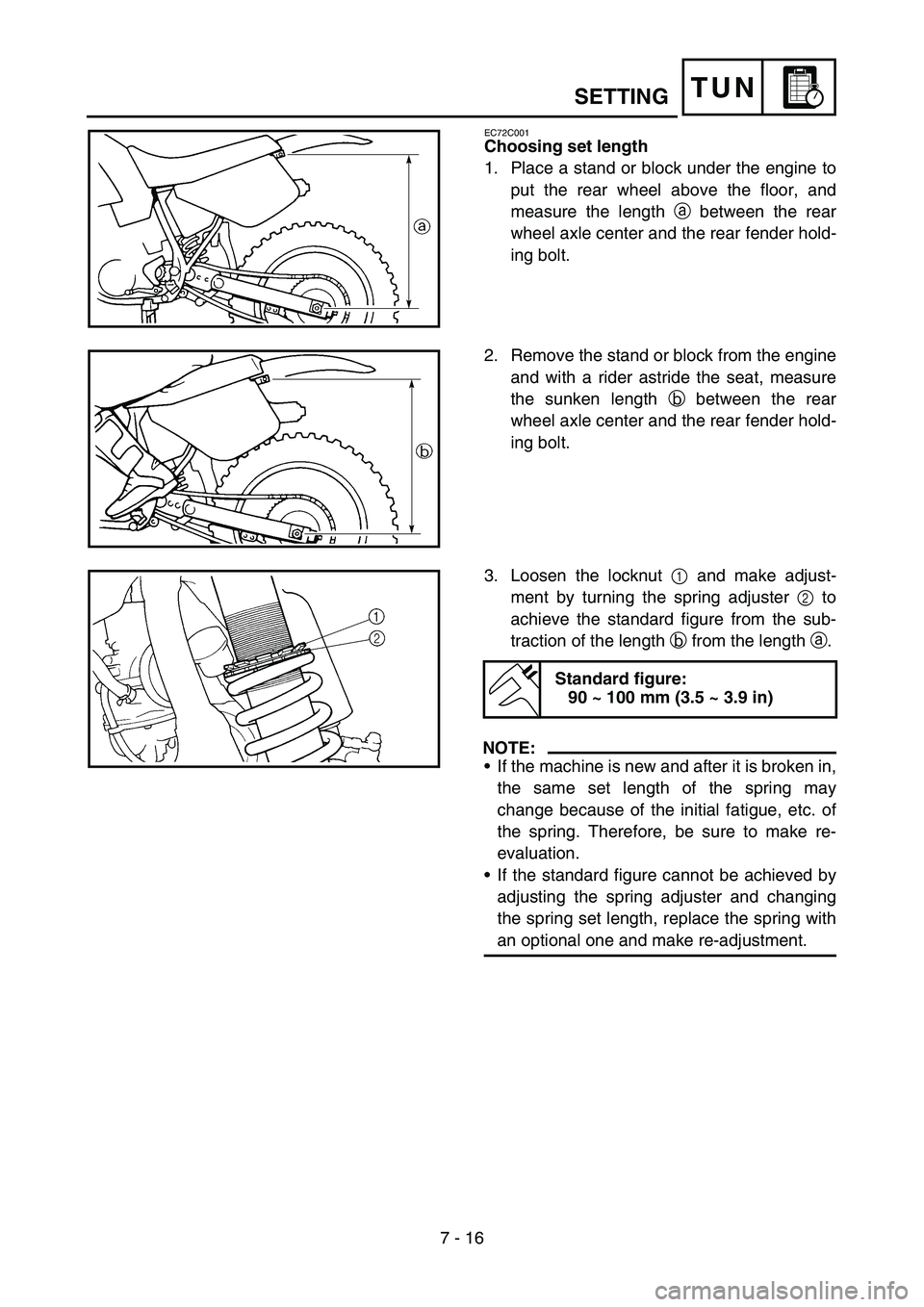
Choosing set length
1. Place a stand or block under the engine to
put the rear wheel above the floor, and
measure the length a between the rear
wheel axle center and the rear fender hold-
ing bolt.
2. Remove the stand or block from the engine
and with a rider astride the seat, measure
the sunken length b between the rear
wheel axle center and the rear fender hold-
ing bolt.
3. Loosen the locknut 1 and make adjust-
ment by turning the spring adjuster 2 to
achieve the standard figure from the sub-
traction of the length b from the length a.
NOTE:
•If the machine is new and after it is broken in,
the same set length of the spring may
change because of the initial fatigue, etc. of
the spring. Therefore, be sure to make re-
evaluation.
•If the standard figure cannot be achieved by
adjusting the spring adjuster and changing
the spring set length, replace the spring with
an optional one and make re-adjustment.
Standard figure:
90 ~ 100 mm (3.5 ~ 3.9 in)
SETTING
Page 642 of 650

7 - 20
TUNSETTING
EC72H002
Suspension setting
•Front fork
NOTE:
•If any of the following symptoms is experienced with the standard position as the base, make
resetting by reference to the adjustment procedure given in the same chart.
•Before any change, set the rear shock absorber sunken length to the standard figure 90 ~ 100 mm
(3.5 ~ 3.9 in).
SymptomSection
Check Adjust
JumpLarge
gapMedium
gapSmall
gap
Stiff over entire rangeCompression damping Turn adjuster counterclockwise (about 2 clicks) to
decrease damping.
Oil amount Decrease oil amount by about 5 ~ 10 cm
3 (0.2 ~
0.4 Imp oz, 0.2 ~ 0.3 US oz).
Spring Replace with soft spring.
Unsmooth movement
over entire rangeOuter tube Check for any bends, dents, and other noticeable
scars, etc. If any, replace affected parts.
Inner tube
Slide metal Replace with a new one for extended use.
Piston metal Replace with a new one for extended use.
Under bracket tightening
torqueRetighten to specified torque.
Poor initial
movementRebound damping Turn adjuster counterclockwise (about 2 clicks) to
decrease damping.
Oil seal Apply grease in oil seal wall.
Soft over entire
range, bottoming outCompression damping Turn adjuster clockwise (about 2 clicks) to increase
damping.
Oil amount Increase oil amount by about 5 ~ 10 cm
3 (0.2 ~
0.4 Imp oz, 0.2 ~ 0.3 US oz).
Spring Replace with stiff spring.
Stiff toward stroke
endOil amountDecrease oil amount by about 5 cm
3 (0.2 Imp oz,
0.2 US oz).
Soft toward stroke
end, bottoming outOil amountIncrease oil amount by about 5 cm
3 (0.2 Imp oz,
0.2 US oz).
Stiff initial movement Compression dampingTurn adjuster counterclockwise (about 2 clicks) to
decrease damping.
Low front, tending to
lower front postureCompression damping Turn adjuster clockwise (about 2 clicks) to increase
damping.
Rebound damping Turn adjuster counterclockwise (about 2 clicks) to
decrease damping.
Balance with rear end Set sunken length for 95 ~ 100 mm (3.7 ~ 3.9 in) when
one passenger is astride seat (lower rear posture).
Oil amount Increase oil amount by about 5 cm
3 (0.2 Imp oz,
0.2 US oz).
“Obtrusive” front,
tending to upper front
postureCompression damping Turn adjuster counterclockwise (about 2 clicks) to
decrease damping.
Balance with rear end Set sunken length for 90 ~ 95 mm (3.5 ~ 3.7 in)
when one passenger is astride seat (upper rear pos-
ture).
Spring Replace with soft spring.
Oil amount Decrease oil amount by about 5 ~ 10 cm
3 (0.2 ~
0.4 Imp oz, 0.2 ~ 0.3 US oz).
Page 643 of 650

7 - 21
TUNSETTING
•Rear shock absorber
NOTE:
•If any of the following symptoms is experienced with the standard position as the base, make
resetting by reference to the adjustment procedure given in the same chart.
•Adjust the rebound damping in 2-click increments or decrements.
•Adjust the low compression damping in 1-click increments or decrements.
•Adjust the high compression damping in 1/6 turn increments or decrements.
SymptomSection
Check Adjust
JumpLarge
gapMedium
gapSmall
gap
Stiff, tending to sinkRebound damping Turn adjuster counterclockwise (about 2 clicks) to
decrease damping.
Spring set length Set sunken length for 90 ~ 100 mm (3.5 ~ 3.9 in)
when one passenger is astride seat.
Spongy and unstableRebound damping Turn adjuster clockwise (about 2 clicks) to increase
damping.
Low compression damp-
ingTurn adjuster clockwise (about 1 click) to increase
damping.
Spring Replace with stiff spring.
Heavy and draggingRebound damping Turn adjuster counterclockwise (about 2 clicks) to
decrease damping.
Spring Replace with soft spring.
Poor road grippingRebound damping Turn adjuster counterclockwise (about 2 clicks) to
decrease damping.
Low compression damp-
ingTurn adjuster clockwise (about 1 clicks) to increase
damping.
High compression damp-
ingTurn adjuster clockwise (about 1/6 clicks) to
increase damping.
Spring set length Set sunken length for 90 ~ 100 mm (3.5 ~ 3.9 in)
when one passenger is astride seat.
Spring Replace with soft spring.
Bottoming outHigh compression damp-
ingTurn adjuster clockwise (about 1/6 turn) to increase
damping.
Spring set length Set sunken length for 90 ~ 100 mm (3.5 ~ 3.9 in)
when one passenger in astride seat.
Spring Replace with stiff spring.
BouncingRebound damping Turn adjuster clockwise (about 2 clicks) to increase
damping.
Spring Replace with soft spring.
Stiff travelHigh compression damp-
ingTurn adjuster counterclockwise (about 1/6 turn) to
decrease damping.
Spring set length Set sunken length for 95 ~ 100 mm (3.7 ~ 3.9 in)
when one passenger is astride seat.
Spring Replace with soft spring.