check YAMAHA YZ450F 2007 Repair Manual
[x] Cancel search | Manufacturer: YAMAHA, Model Year: 2007, Model line: YZ450F, Model: YAMAHA YZ450F 2007Pages: 650, PDF Size: 20.67 MB
Page 514 of 650
5 - 38
CHASFRONT FORK
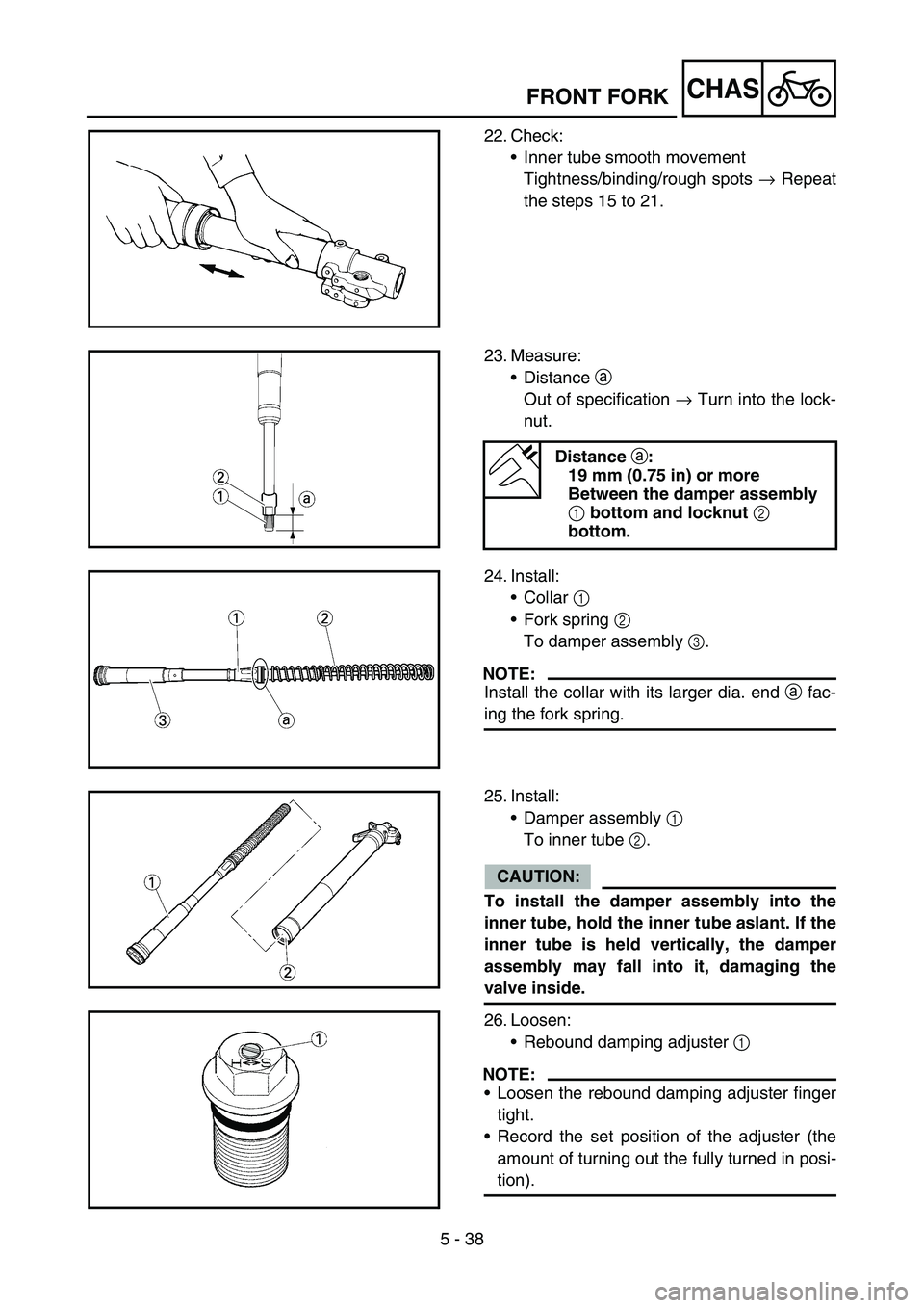
22. Check:
Inner tube smooth movement
Tightness/binding/rough spots → Repeat
the steps 15 to 21.
23. Measure:
Distance a
Out of specification → Turn into the lock-
nut.
Distance
a:
19 mm (0.75 in) or more
Between the damper assembly
1 bottom and locknut
2
bottom.
24. Install:
Collar 1
Fork spring 2
To damper assembly 3.
NOTE:
Install the collar with its larger dia. end a fac-
ing the fork spring.
25. Install:
Damper assembly 1
To inner tube 2.
CAUTION:
To install the damper assembly into the
inner tube, hold the inner tube aslant. If the
inner tube is held vertically, the damper
assembly may fall into it, damaging the
valve inside.
26. Loosen:
Rebound damping adjuster 1
NOTE:
Loosen the rebound damping adjuster finger
tight.
Record the set position of the adjuster (the
amount of turning out the fully turned in posi-
tion).
Page 532 of 650
5 - 47
CHASHANDLEBAR
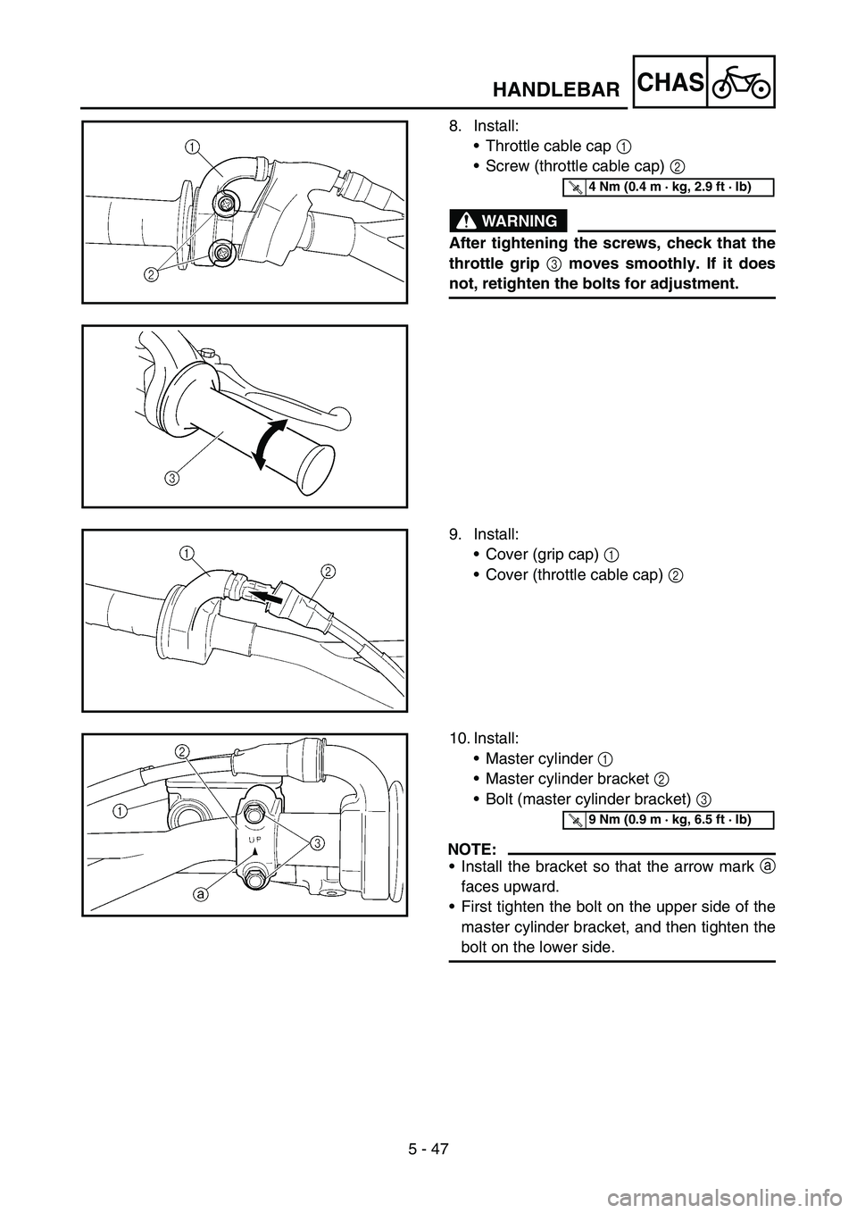
8. Install:
•Throttle cable cap 1
•Screw (throttle cable cap) 2
WARNING
After tightening the screws, check that the
throttle grip
3 moves smoothly. If it does
not, retighten the bolts for adjustment.
T R..4 Nm (0.4 m · kg, 2.9 ft · lb)
9. Install:
•Cover (grip cap) 1
•Cover (throttle cable cap) 2
10. Install:
•Master cylinder 1
•Master cylinder bracket 2
•Bolt (master cylinder bracket) 3
NOTE:
•Install the bracket so that the arrow mark a
faces upward.
•First tighten the bolt on the upper side of the
master cylinder bracket, and then tighten the
bolt on the lower side.
T R..9 Nm (0.9 m · kg, 6.5 ft · lb)
Page 542 of 650
5 - 52
CHAS
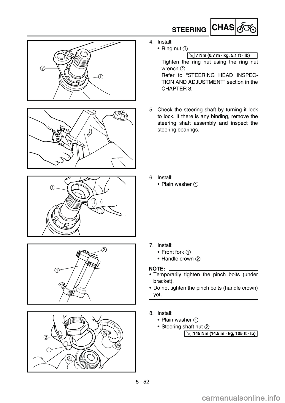
4. Install:
•Ring nut 1
Tighten the ring nut using the ring nut
wrench 2.
Refer to “STEERING HEAD INSPEC-
TION AND ADJUSTMENT” section in the
CHAPTER 3.
T R..7 Nm (0.7 m · kg, 5.1 ft · lb)
5. Check the steering shaft by turning it lock
to lock. If there is any binding, remove the
steering shaft assembly and inspect the
steering bearings.
6. Install:
•Plain washer 1
7. Install:
•Front fork 1
•Handle crown 2
NOTE:
•Temporarily tighten the pinch bolts (under
bracket).
•Do not tighten the pinch bolts (handle crown)
yet.
8. Install:
•Plain washer 1
•Steering shaft nut 2
T R..145 Nm (14.5 m · kg, 105 ft · lb)
STEERING
Page 544 of 650
5 - 53
CHASSTEERING
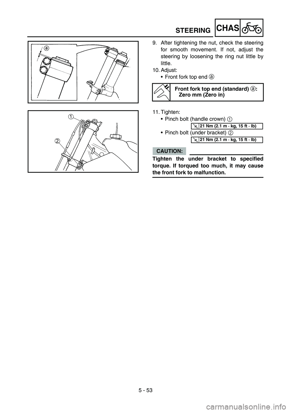
9. After tightening the nut, check the steering
for smooth movement. If not, adjust the
steering by loosening the ring nut little by
little.
10. Adjust:
•Front fork top end a
Front fork top end (standard)
a:
Zero mm (Zero in)
11. Tighten:
•Pinch bolt (handle crown) 1
•Pinch bolt (under bracket) 2
CAUTION:
Tighten the under bracket to specified
torque. If torqued too much, it may cause
the front fork to malfunction.
T R..21 Nm (2.1 m · kg, 15 ft · lb)
T R..21 Nm (2.1 m · kg, 15 ft · lb)
Page 556 of 650

5 - 59
CHASSWINGARM
3. Install:
•Collar 1
To connecting rod 2.
NOTE:
Apply the molybdenum disulfide grease on the
collar and oil seal lips.
4. Install:
•Connecting rod 1
•Bolt (connecting rod) 2
•Plain washer 3
•Nut (connecting rod) 4
To relay arm 5.
NOTE:
Apply the molybdenum disulfide grease on the
bolt.
T R..80 Nm (8.0 m · kg, 58 ft · lb)
5. Install:
•Relay arm 1
•Bolt (relay arm) 2
•Plain washer 3
•Nut (relay arm) 4
To swingarm.
NOTE:
•Apply the molybdenum disulfide grease on
the bolt circumference and threaded portion.
•Do not tighten the nut yet.
6. Install:
•Swingarm 1
•Pivot shaft 2
NOTE:
•Apply the molybdenum disulfide grease on
the pivot shaft.
•Insert the pivot shaft from right side.
T R..85 Nm (8.5 m · kg, 61 ft · lb)
7. Check:
•Swingarm side play a
Free play exists → Replace thrust bear-
ing.
•Swingarm up and down movement b
Unsmooth movement/binding/rough
spots → Grease or replace bearings,
bushes and collars.
Page 581 of 650
–+ELEC
6 - 3
IGNITION SYSTEM
EC620000
IGNITION SYSTEM
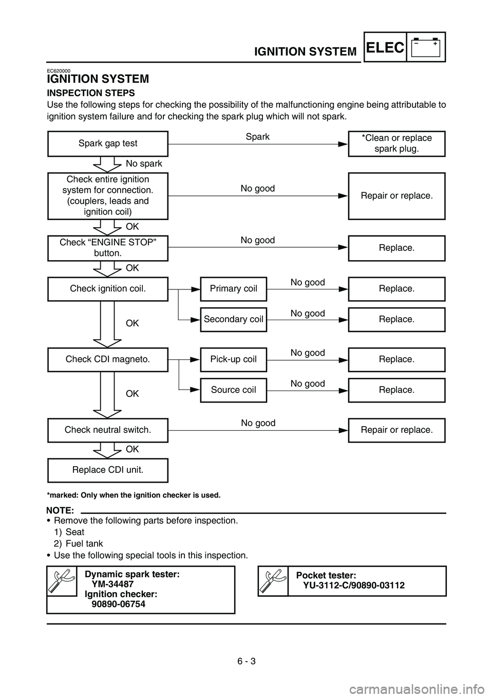
INSPECTION STEPS
Use the following steps for checking the possibility of the malfunctioning engine being attributable to
ignition system failure and for checking the spark plug which will not spark.
*marked: Only when the ignition checker is used.
NOTE:
•Remove the following parts before inspection.
1) Seat
2) Fuel tank
•Use the following special tools in this inspection.
Dynamic spark tester:
YM-34487
Ignition checker:
90890-06754Pocket tester:
YU-3112-C/90890-03112
Spark gap test*Clean or replace
spark plug.
Check entire ignition
system for connection.
(couplers, leads and
ignition coil)Repair or replace.
Check “ENGINE STOP”
button.Replace.
Check ignition coil. Primary coil Replace.
Secondary coil Replace.
Check CDI magneto. Pick-up coil Replace.
Source coil Replace.
Check neutral switch. Repair or replace.
Replace CDI unit.
No spark
OK
OK
OK
OK
OK
Spark
No good
No good
No good
No good
No good
No good
No good
Page 584 of 650
6 - 4
–+ELECIGNITION SYSTEM
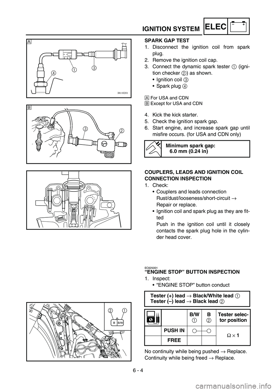
SPARK GAP TEST
1. Disconnect the ignition coil from spark
plug.
2. Remove the ignition coil cap.
3. Connect the dynamic spark tester 1 (igni-
tion checker 2) as shown.
•Ignition coil 3
•Spark plug 4
ÈFor USA and CDN
ÉExcept for USA and CDN
4. Kick the kick starter.
5. Check the ignition spark gap.
6. Start engine, and increase spark gap until
misfire occurs. (for USA and CDN only)
Minimum spark gap:
6.0 mm (0.24 in)
È
É
COUPLERS, LEADS AND IGNITION COIL
CONNECTION INSPECTION
1. Check:
•Couplers and leads connection
Rust/dust/looseness/short-circuit →
Repair or replace.
•Ignition coil and spark plug as they are fit-
ted
Push in the ignition coil until it closely
contacts the spark plug hole in the cylin-
der head cover.
EC625001
“ENGINE STOP” BUTTON INSPECTION
1. Inspect:
•“ENGINE STOP” button conduct
No continuity while being pushed → Replace.
Continuity while being freed → Replace. Tester (+) lead
→ Black/White lead
1
Tester (–) lead
→ Black lead
2
B/W
1 B
2 Tester selec-
tor position
PUSH IN
Ω
× 1
FREE1 2
B/W B
Page 588 of 650
6 - 6
–+ELECIGNITION SYSTEM
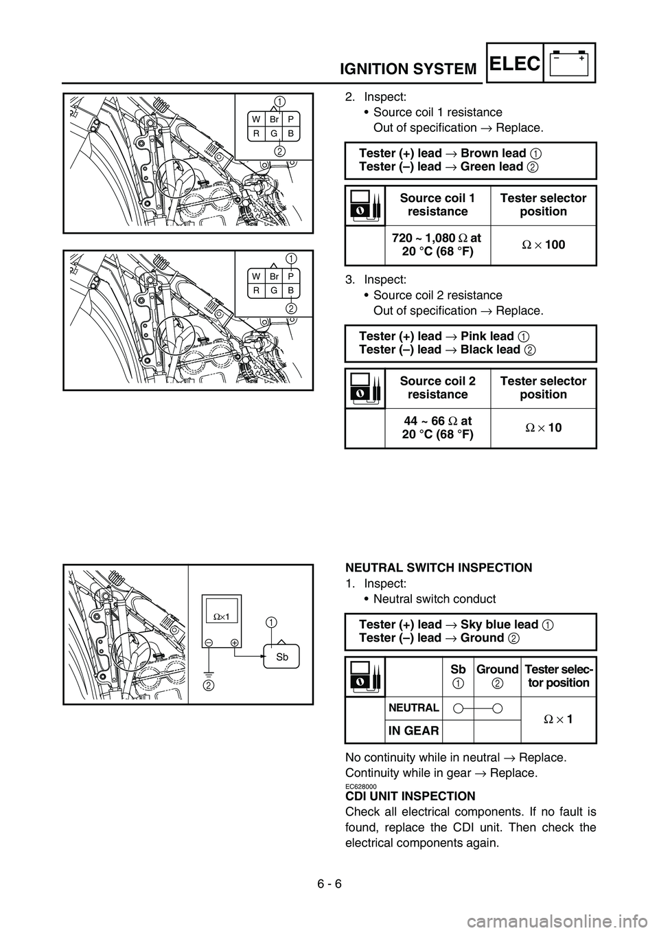
2. Inspect:
•Source coil 1 resistance
Out of specification → Replace.
3. Inspect:
•Source coil 2 resistance
Out of specification → Replace. Tester (+) lead
→ Brown lead
1
Tester (–) lead
→ Green lead
2
Source coil 1
resistanceTester selector
position
720 ~ 1,080
Ω at
20 °C (68 °F)Ω
× 100
Tester (+) lead
→ Pink lead
1
Tester (–) lead
→ Black lead
2
Source coil 2
resistanceTester selector
position
44 ~ 66
Ω at
20 °C (68 °F)Ω
× 10
W
RBr
GP
B
2 1
2
1
W
RBr
GP
B
NEUTRAL SWITCH INSPECTION
1. Inspect:
•Neutral switch conduct
No continuity while in neutral → Replace.
Continuity while in gear → Replace.
EC628000
CDI UNIT INSPECTION
Check all electrical components. If no fault is
found, replace the CDI unit. Then check the
electrical components again.Tester (+) lead
→ Sky blue lead
1
Tester (–) lead
→ Ground
2
Sb
1 Ground
2 Tester selec-
tor position
NEUTRAL
Ω
× 1
IN GEAR
–+ Ω×1
1
2
Sb
Page 590 of 650
–+ELEC
6 - 7
TPS (THROTTLE POSITION SENSOR) SYSTEM
EC690000
TPS (THROTTLE POSITION SENSOR) SYSTEM
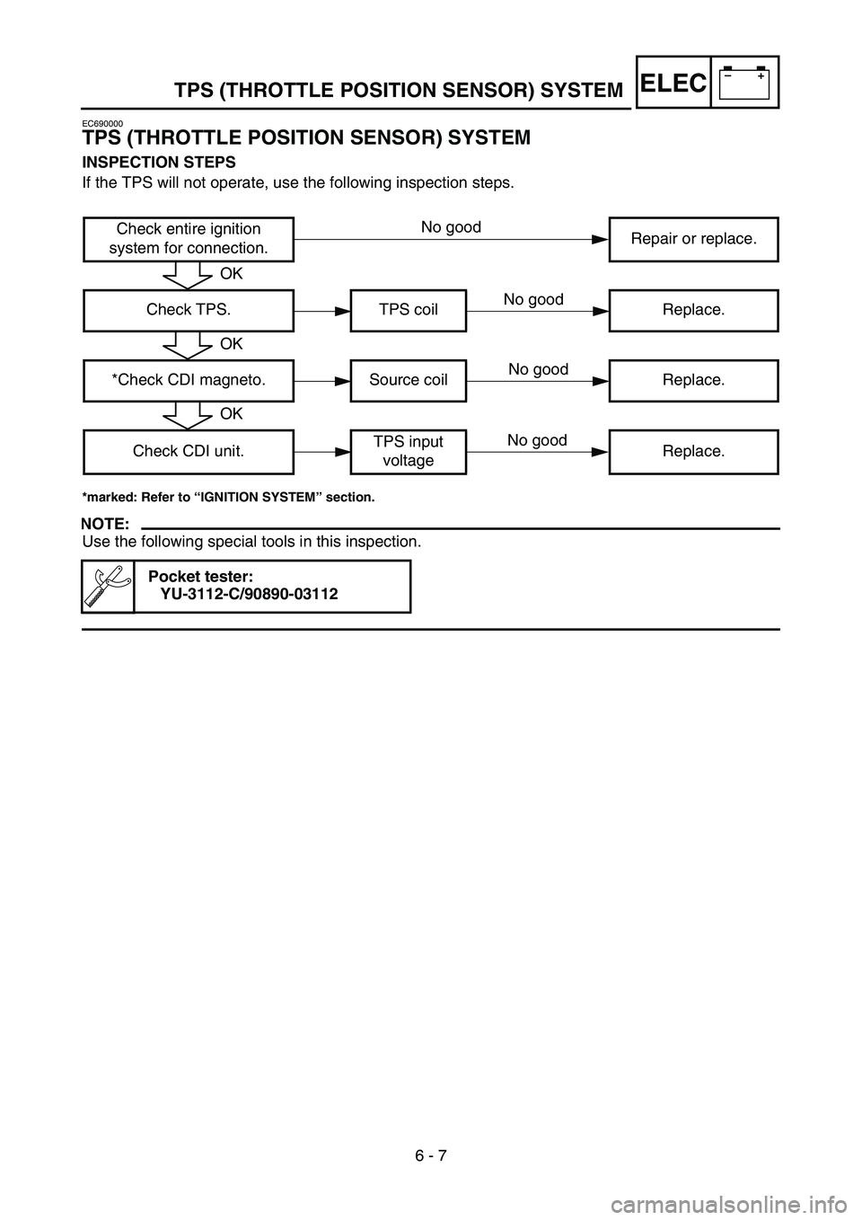
INSPECTION STEPS
If the TPS will not operate, use the following inspection steps.
*marked: Refer to “IGNITION SYSTEM” section.
NOTE:
Use the following special tools in this inspection.
Pocket tester:
YU-3112-C/90890-03112
Check entire ignition
system for connection.Repair or replace.
Check TPS. TPS coil Replace.
*Check CDI magneto. Source coil Replace.
Check CDI unit.TPS input
voltageReplace.
OK
OK
OK
No good
No good
No good
No good
Page 594 of 650
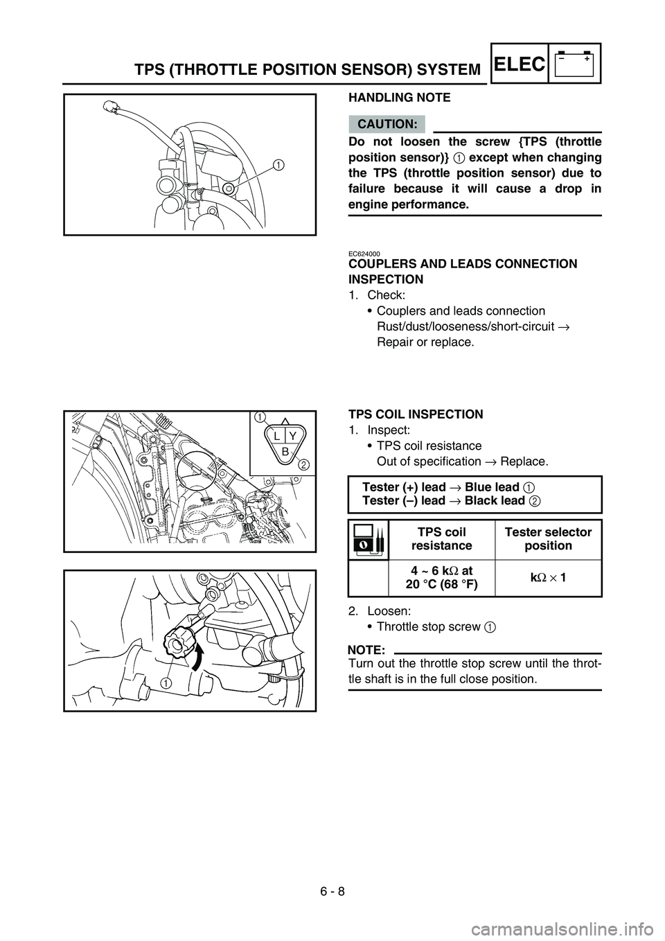
6 - 8
–+ELECTPS (THROTTLE POSITION SENSOR) SYSTEM
HANDLING NOTE
CAUTION:
Do not loosen the screw {TPS (throttle
position sensor)}
1 except when changing
the TPS (throttle position sensor) due to
failure because it will cause a drop in
engine performance.
1
EC624000
COUPLERS AND LEADS CONNECTION
INSPECTION
1. Check:
•Couplers and leads connection
Rust/dust/looseness/short-circuit →
Repair or replace.
TPS COIL INSPECTION
1. Inspect:
•TPS coil resistance
Out of specification → Replace.
2. Loosen:
•Throttle stop screw 1
NOTE:
Turn out the throttle stop screw until the throt-
tle shaft is in the full close position.Tester (+) lead
→ Blue lead
1
Tester (–) lead
→ Black lead
2
TPS coil
resistanceTester selector
position
4 ~ 6 kΩ at
20 °C (68 °F)kΩ × 1