ignition YAMAHA YZ450F 2014 User Guide
[x] Cancel search | Manufacturer: YAMAHA, Model Year: 2014, Model line: YZ450F, Model: YAMAHA YZ450F 2014Pages: 360, PDF Size: 11.76 MB
Page 198 of 360
ENGINE REMOVAL
5-3
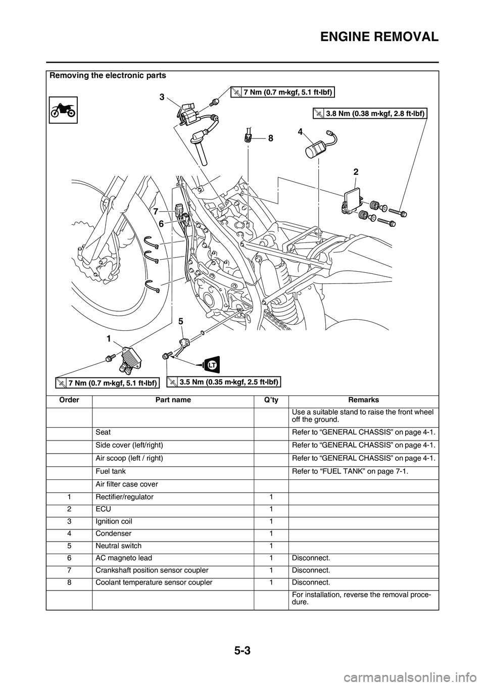
Removing the electronic parts
OrderPart nameQ’tyRemarks
Use a suitable stand to raise the front wheel
off the ground.
SeatRefer to “GENERAL CHASSIS” on page 4-1.
Side cover (left/right)Refer to “GENERAL CHASSIS” on page 4-1.
Air scoop (left / right)Refer to “GENERAL CHASSIS” on page 4-1.
Fuel tankRefer to “FUEL TANK” on page 7-1.
Air filter case cover
1Rectifier/regulator1
2ECU1
3Ignition coil1
4Condenser1
5Neutral switch1
6AC magneto lead1Disconnect.
7Crankshaft position sensor coupler1Disconnect.
8Coolant temperature sensor coupler1Disconnect.
For installation, reverse the removal proce-dure.
T.R.
T.R.
T.R.T.R.
8 3
7
6
154
2
LT
Page 284 of 360
THROTTLE BODY
7-5
EAS1SL1314
THROTTLE BODY
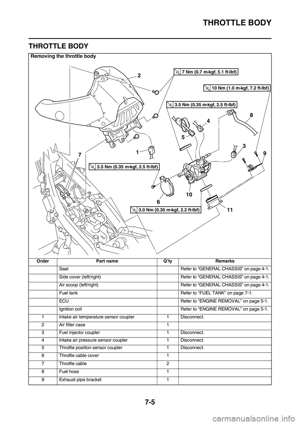
Removing the throttle body
OrderPart nameQ’tyRemarks
SeatRefer to “GENERAL CHASSIS” on page 4-1.
Side cover (left/right)Refer to “GENERAL CHASSIS” on page 4-1.
Air scoop (left/right)Refer to “GENERAL CHASSIS” on page 4-1.
Fuel tankRefer to “FUEL TANK” on page 7-1.
ECURefer to “ENGINE REMOVAL” on page 5-1.
Ignition coilRefer to “ENGINE REMOVAL” on page 5-1.
1Intake air temperature sensor coupler1Disconnect.
2Air filter case1
3Fuel injector coupler1Disconnect.
4Intake air pressure sensor coupler1Disconnect.
5Throttle position sensor coupler1Disconnect.
6Throttle cable cover1
7Throttle cable2
8Fuel hose1
9Exhaust pipe bracket1
2
1
6
10
11
9
8
3
7
5
4
3.5 Nm (0.35 mkgf, 2.5 ftIbf)T.R.
3.5 Nm (0.35 mkgf, 2.5 ftIbf)T.R.
7 Nm (0.7 mkgf, 5.1 ftIbf)T.R.
3.0 Nm (0.30 mkgf, 2.2 ftIbf)T.R.
10 Nm (1.0 mkgf, 7.2 ftIbf)T.R.
Page 289 of 360
8
ELECTRICAL SYSTEM
IGNITION SYSTEM.......................................................................................... 8-2
CIRCUIT DIAGRAM ................................................................................... 8-2
TROUBLESHOOTING ............................................................................... 8-4
CHARGING SYSTEM....................................................................................... 8-6
CIRCUIT DIAGRAM ................................................................................... 8-6
TROUBLE SHOOTING .............................................................................. 8-8
FUEL INJECTION SYSTEM........................................................................... 8-10
CIRCUIT DIAGRAM ................................................................................. 8-10
YAMAHA DIAGNOSTIC TOOL ................................................................ 8-12
TROUBLESHOOTING DETAILS ............................................................. 8-13
FUEL PUMP SYSTEM.................................................................................... 8-32
CIRCUIT DIAGRAM ................................................................................. 8-32
TROUBLESHOOTING ............................................................................. 8-34
ELECTRICAL COMPONENTS....................................................................... 8-36
CHECKING THE SWITCHES .................................................................. 8-38
CHECKING THE IGNITION SPARK GAP................................................ 8-41
CHECKING THE SPARK PLUG CAP ...................................................... 8-41
CHECKING THE IGNITION COIL ............................................................ 8-41
CHECKING THE CRANKSHAFT POSITION SENSOR........................... 8-42
CHECKING THE ECU .............................................................................. 8-43
CHECKING THE STATOR COIL ............................................................. 8-43
CHECKING THE RECTIFIER/REGULATOR ........................................... 8-43
CHECKING THE COOLANT TEMPERATURE SENSOR........................ 8-44
CHECKING THE THROTTLE POSITION SENSOR ................................ 8-44
CHECKING THE THROTTLE POSITION SENSOR
INPUT VOLTAGE .................................................................................... 8-43
CHECKING THE INTAKE AIR PRESSURE SENSOR ............................ 8-46
CHECKING THE INTAKE AIR TEMPERATURE SENSOR ..................... 8-46
CHECKING THE NEUTRAL SWITCH ..................................................... 8-46
CHECKING THE FUEL INJECTOR ......................................................... 8-47
Page 292 of 360
IGNITION SYSTEM
8-2
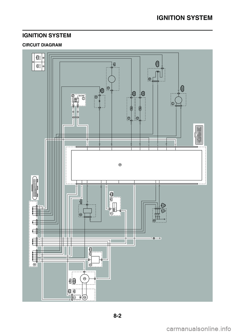
IGNITION SYSTEM
EAS1SL1321CIRCUIT DIAGRAM
B/LGy
BR
A
A
AA
B
RR R R R R R
B
B
B
RR
R
Lg
LgB/WB/Y
B/YB
B
BP
PP
Sb
B/LP/B
P/B
YL
YL
L
G/WBr/W
G/WBr/W
B/LB/L
B/L
B/L
B/R
B/R
R/B
R/B
O
OROR
OR
R
R
SbB
GyR
B/W
P L B/L
B/L Gy B/L B/L B/L B/L B/L
LL
PP
BBBB
PP
Sb
RB
B/RR
RB
B/Y PSb
BB
RR/B
LYB/L
B/W RLg
B/LBr/W
B/L P/B LB/LG/W
BB/Y
BB/L B/L B/L B/L B/L B/LBBBBRR
PPPL L LRR RR R
B
O P
Gy
R
B/Y Sb
P/B
R/B Lg B/RG/WBr/WB/L L Y
RB
B/L
Gy
R
O
O
R(BLACK) (BLACK)
B/W
4
1
3
2
5
67
8
10
9
1211
13
1415
16
17
Page 293 of 360
IGNITION SYSTEM
8-3
EAS1SL1322
1. Crankshaft position sensor
2. AC magneto
3. Rectifier/regulator
4. Joint connector
5. Condenser
7. Engine stop switch
9. ECU
10.Ignition coil
11.Spark plug
Page 294 of 360
IGNITION SYSTEM
8-4
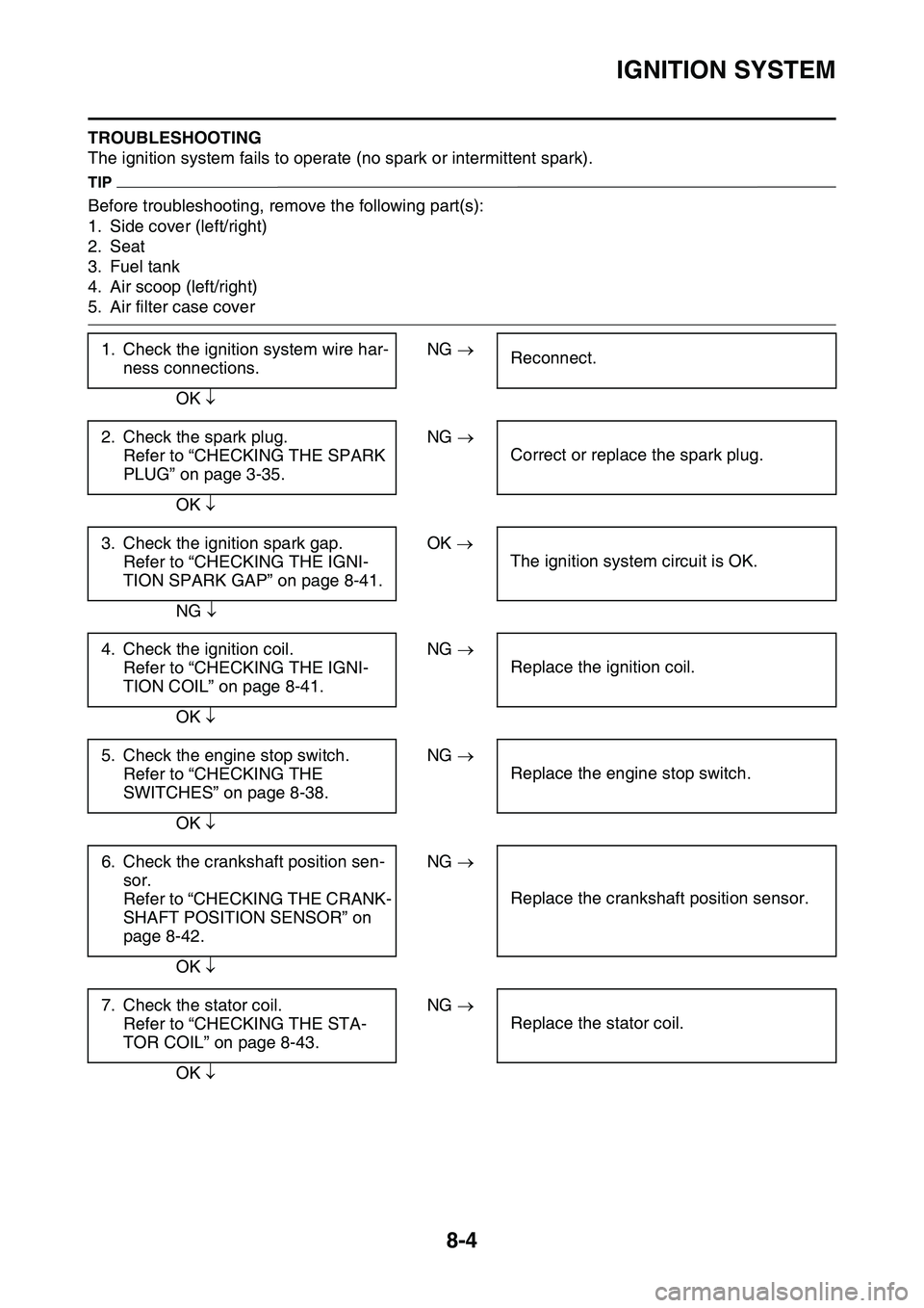
TROUBLESHOOTING
The ignition system fails to operate (no spark or intermittent spark).
TIP
Before troubleshooting, remove the following part(s):
1. Side cover (left/right)
2. Seat
3. Fuel tank
4. Air scoop (left/right)
5. Air filter case cover
1. Check the ignition system wire har-
ness connections.
NG Reconnect.
OK
2. Check the spark plug.
Refer to “CHECKING THE SPARK
PLUG” on page 3-35.
NG
Correct or replace the spark plug.
OK
3. Check the ignition spark gap.
Refer to “CHECKING THE IGNI-
TION SPARK GAP” on page 8-41.
OK
The ignition system circuit is OK.
NG
4. Check the ignition coil.
Refer to “CHECKING THE IGNI-
TION COIL” on page 8-41.
NG
Replace the ignition coil.
OK
5. Check the engine stop switch.
Refer to “CHECKING THE
SWITCHES” on page 8-38.
NG
Replace the engine stop switch.
OK
6. Check the crankshaft position sen-
sor.
Refer to “CHECKING THE CRANK-
SHAFT POSITION SENSOR” on
page 8-42.
NG
Replace the crankshaft position sensor.
OK
7. Check the stator coil.
Refer to “CHECKING THE STA-
TOR COIL” on page 8-43.
NG
Replace the stator coil.
OK
Page 295 of 360
IGNITION SYSTEM
8-5
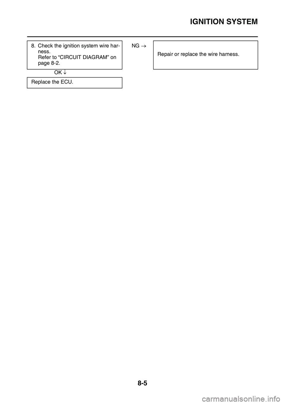
8. Check the ignition system wire har-
ness.
Refer to “CIRCUIT DIAGRAM” on
page 8-2.
NG
Repair or replace the wire harness.
OK
Replace the ECU.
Page 302 of 360
FUEL INJECTION SYSTEM
8-12
YAMAHA DIAGNOSTIC TOOL
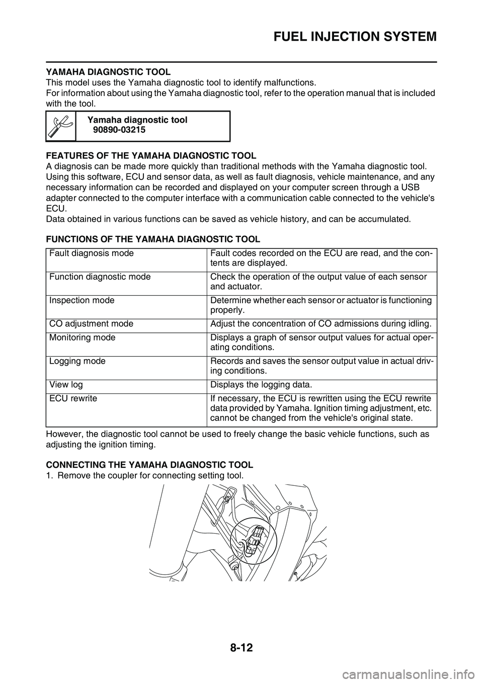
This model uses the Yamaha diagnostic tool to identify malfunctions.
For information about using the Yamaha diagnostic tool, refer to the operation manual that is included
with the tool.
FEATURES OF THE YAMAHA DIAGNOSTIC TOOL
A diagnosis can be made more quickly than traditional methods with the Yamaha diagnostic tool.
Using this software, ECU and sensor data, as well as fault diagnosis, vehicle maintenance, and any
necessary information can be recorded and displayed on your computer screen through a USB
adapter connected to the computer interface with a communication cable connected to the vehicle's
ECU.
Data obtained in various functions can be saved as vehicle history, and can be accumulated.
FUNCTIONS OF THE YAMAHA DIAGNOSTIC TOOL
However, the diagnostic tool cannot be used to freely change the basic vehicle functions, such as
adjusting the ignition timing.
CONNECTING THE YAMAHA DIAGNOSTIC TOOL
1. Remove the coupler for connecting setting tool.
Yamaha diagnostic tool
90890-03215
Fault diagnosis modeFault codes recorded on the ECU are read, and the con-
tents are displayed.
Function diagnostic modeCheck the operation of the output value of each sensor
and actuator.
Inspection modeDetermine whether each sensor or actuator is functioning
properly.
CO adjustment modeAdjust the concentration of CO admissions during idling.
Monitoring modeDisplays a graph of sensor output values for actual oper-
ating conditions.
Logging modeRecords and saves the sensor output value in actual driv-
ing conditions.
View logDisplays the logging data.
ECU rewriteIf necessary, the ECU is rewritten using the ECU rewrite
data provided by Yamaha. Ignition timing adjustment, etc.
cannot be changed from the vehicle's original state.
Page 313 of 360
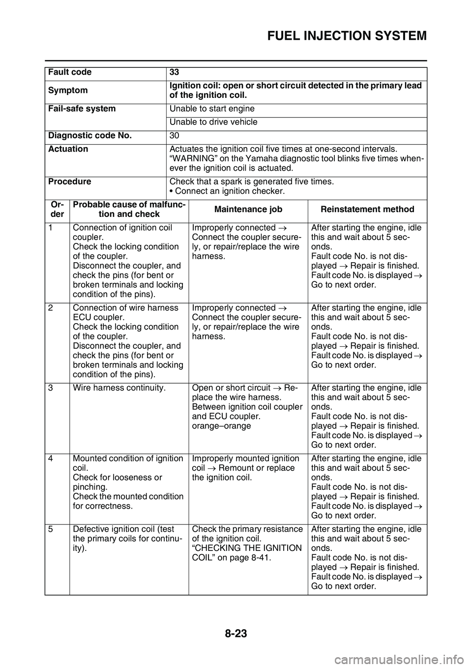
FUEL INJECTION SYSTEM
8-23
Fault code33
SymptomIgnition coil: open or short circuit detected in the primary lead
of the ignition coil.
Fail-safe systemUnable to start engine
Unable to drive vehicle
Diagnostic code No.30
ActuationActuates the ignition coil five times at one-second intervals.
“WARNING” on the Yamaha diagnostic tool blinks five times when-
ever the ignition coil is actuated.
ProcedureCheck that a spark is generated five times.
• Connect an ignition checker.
Or-
der
Probable cause of malfunc-
tion and checkMaintenance jobReinstatement method
1Connection of ignition coil
coupler.
Check the locking condition
of the coupler.
Disconnect the coupler, and
check the pins (for bent or
broken terminals and locking
condition of the pins).
Improperly connected
Connect the coupler secure
-
ly, or repair/replace the wire
harness.
After starting the engine, idle
this and wait about 5 sec
-
onds.
Fault code No. is not dis-
played Repair is finished.
Fault code No. is displayed
Go to next order.
2Connection of wire harness
ECU coupler.
Check the locking condition
of the coupler.
Disconnect the coupler, and
check the pins (for bent or
broken terminals and locking
condition of the pins).
Improperly connected
Connect the coupler secure
-
ly, or repair/replace the wire
harness.
After starting the engine, idle
this and wait about 5 sec
-
onds.
Fault code No. is not dis-
played Repair is finished.
Fault code No. is displayed
Go to next order.
3Wire harness continuity.Open or short circuit Re-
place the wire harness.
Between ignition coil coupler
and ECU coupler.
orange–orange
After starting the engine, idle
this and wait about 5 sec
-
onds.
Fault code No. is not dis-
played Repair is finished.
Fault code No. is displayed
Go to next order.
4Mounted condition of ignition
coil.
Check for looseness or
pinching.
Check the mounted condition
for correctness.
Improperly mounted ignition
coil Remount or replace
the ignition coil.After starting the engine, idle
this and wait about 5 sec
-
onds.
Fault code No. is not dis-
played Repair is finished.
Fault code No. is displayed
Go to next order.
5Defective ignition coil (test
the primary coils for continu
-
ity).
Check the primary resistance
of the ignition coil.
“CHECKING THE IGNITION
COIL” on page 8-41.
After starting the engine, idle
this and wait about 5 sec
-
onds.
Fault code No. is not dis-
played Repair is finished.
Fault code No. is displayed
Go to next order.
Page 314 of 360
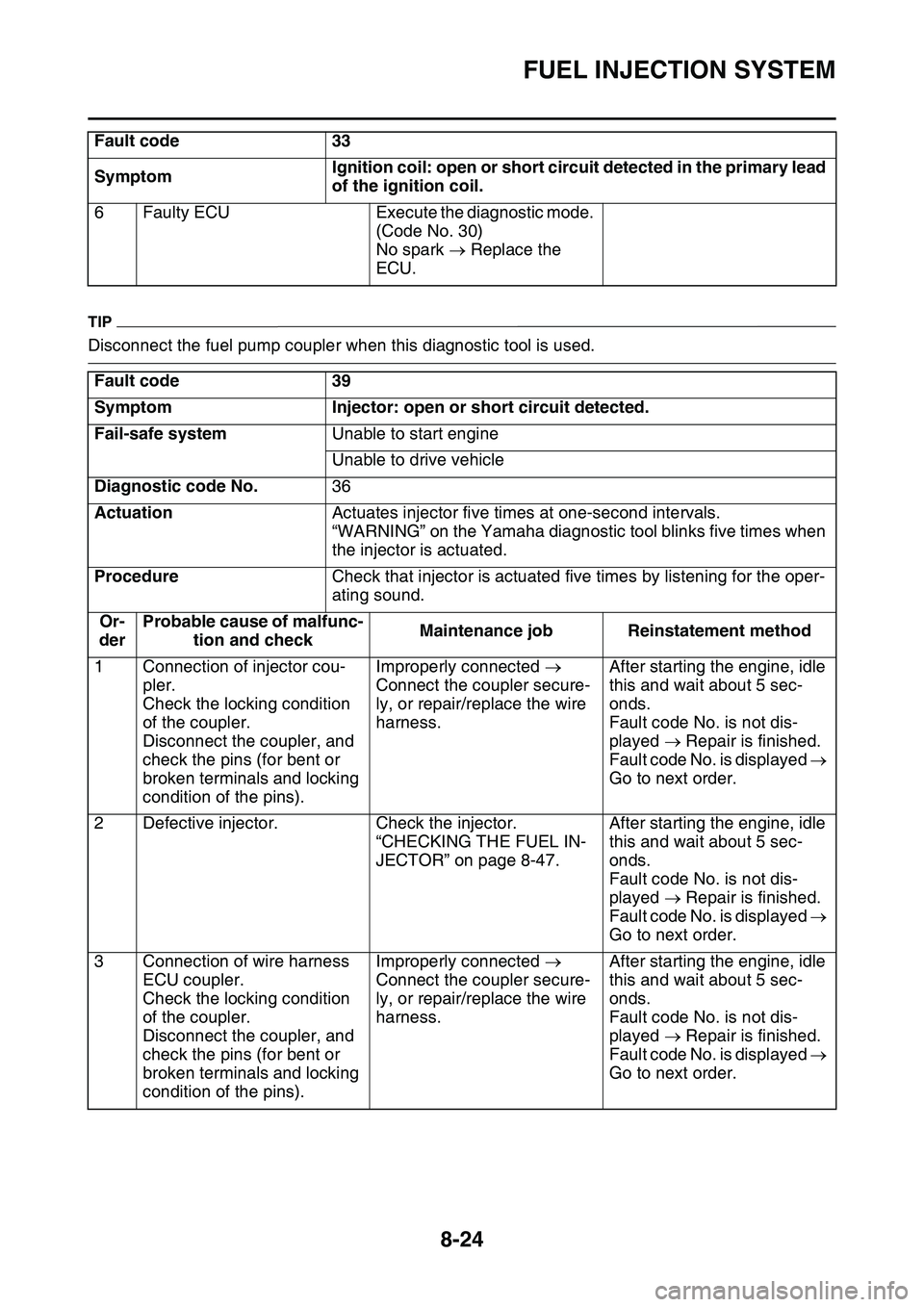
FUEL INJECTION SYSTEM
8-24
TIP
Disconnect the fuel pump coupler when this diagnostic tool is used.
6Faulty ECUExecute the diagnostic mode.
(Code No. 30)
No spark Replace the
ECU.
Fault code39
SymptomInjector: open or short circuit detected.
Fail-safe systemUnable to start engine
Unable to drive vehicle
Diagnostic code No.36
ActuationActuates injector five times at one-second intervals.
“WARNING” on the Yamaha diagnostic tool blinks five times when
the injector is actuated.
ProcedureCheck that injector is actuated five times by listening for the oper-
ating sound.
Or-
der
Probable cause of malfunc-
tion and checkMaintenance jobReinstatement method
1Connection of injector cou-
pler.
Check the locking condition
of the coupler.
Disconnect the coupler, and
check the pins (for bent or
broken terminals and locking
condition of the pins).
Improperly connected
Connect the coupler secure
-
ly, or repair/replace the wire
harness.
After starting the engine, idle
this and wait about 5 sec
-
onds.
Fault code No. is not dis-
played Repair is finished.
Fault code No. is displayed
Go to next order.
2Defective injector.Check the injector.
“CHECKING THE FUEL IN-
JECTOR” on page 8-47.
After starting the engine, idle
this and wait about 5 sec
-
onds.
Fault code No. is not dis-
played Repair is finished.
Fault code No. is displayed
Go to next order.
3Connection of wire harness
ECU coupler.
Check the locking condition
of the coupler.
Disconnect the coupler, and
check the pins (for bent or
broken terminals and locking
condition of the pins).
Improperly connected
Connect the coupler secure
-
ly, or repair/replace the wire
harness.
After starting the engine, idle
this and wait about 5 sec
-
onds.
Fault code No. is not dis-
played Repair is finished.
Fault code No. is displayed
Go to next order.
Fault code 33
SymptomIgnition coil: open or short circuit detected in the primary lead
of the ignition coil.