YAMAHA YZ450F 2014 Owners Manual
Manufacturer: YAMAHA, Model Year: 2014, Model line: YZ450F, Model: YAMAHA YZ450F 2014Pages: 360, PDF Size: 11.76 MB
Page 331 of 360
ELECTRICAL COMPONENTS
8-41
EAS1SL1335CHECKING THE IGNITION SPARK GAP
1. Check:
• Ignition spark gap
Out of specification Perform the ignition
system troubleshooting.
Refer to “TROUBLESHOOTING” on page 8-
4.
TIP
If the ignition spark gap is within specification,
the ignition system circuit is operating normally.
▼▼▼▼▼▼▼▼▼▼▼▼▼▼▼▼▼▼▼▼▼▼▼▼▼▼▼▼▼▼▼▼
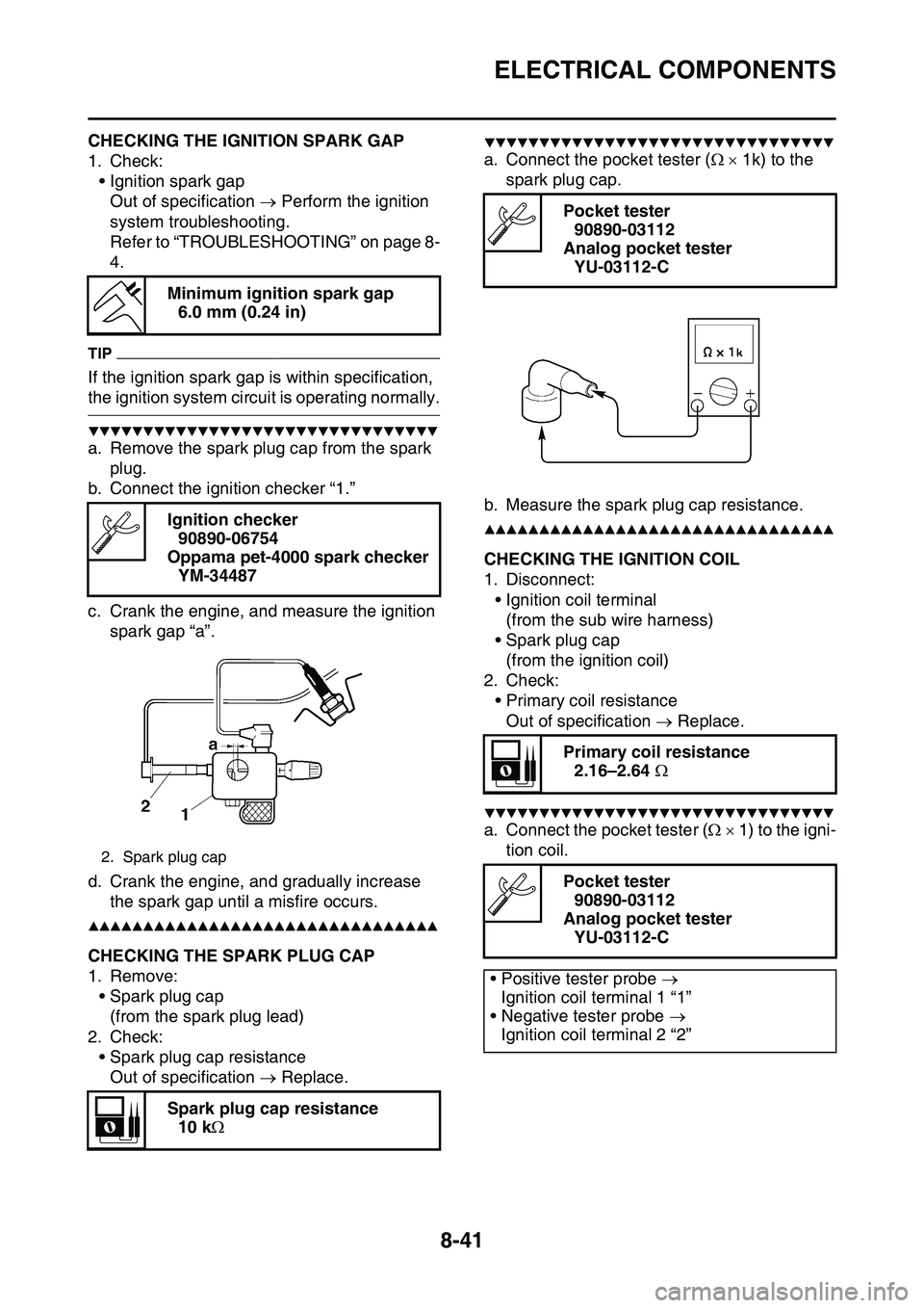
a. Remove the spark plug cap from the spark
plug.
b. Connect the ignition checker “1.”
c. Crank the engine, and measure the ignition
spark gap “a”.
d. Crank the engine, and gradually increase
the spark gap until a misfire occurs.
▲▲▲▲▲▲▲▲▲▲▲▲▲▲▲▲▲▲▲▲▲▲▲▲▲▲▲▲▲▲▲▲
EAS1SL1336CHECKING THE SPARK PLUG CAP
1. Remove:
• Spark plug cap
(from the spark plug lead)
2. Check:
• Spark plug cap resistance
Out of specification Replace.
▼▼▼▼▼▼▼▼▼▼▼▼▼▼▼▼▼▼▼▼▼▼▼▼▼▼▼▼▼▼▼▼
a. Connect the pocket tester ( 1k) to the
spark plug cap.
b. Measure the spark plug cap resistance.
▲▲▲▲▲▲▲▲▲▲▲▲▲▲▲▲▲▲▲▲▲▲▲▲▲▲▲▲▲▲▲▲
EAS1SL1337CHECKING THE IGNITION COIL
1. Disconnect:
• Ignition coil terminal
(from the sub wire harness)
• Spark plug cap
(from the ignition coil)
2. Check:
• Primary coil resistance
Out of specification Replace.
▼▼▼▼▼▼▼▼▼▼▼▼▼▼▼▼▼▼▼▼▼▼▼▼▼▼▼▼▼▼▼▼
a. Connect the pocket tester ( 1) to the igni-
tion coil.
Minimum ignition spark gap
6.0 mm (0.24 in)
Ignition checker
90890-06754
Oppama pet-4000 spark checker
YM-34487
2. Spark plug cap
Spark plug cap resistance
10 k
Pocket tester
90890-03112
Analog pocket tester
YU-03112-C
Primary coil resistance
2.16–2.64
Pocket tester
90890-03112
Analog pocket tester
YU-03112-C
• Positive tester probe
Ignition coil terminal 1 “1”
• Negative tester probe
Ignition coil terminal 2 “2”
Page 332 of 360
ELECTRICAL COMPONENTS
8-42
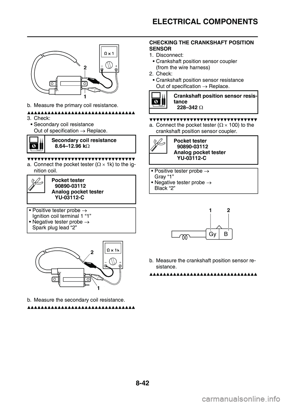
b. Measure the primary coil resistance.
▲▲▲▲▲▲▲▲▲▲▲▲▲▲▲▲▲▲▲▲▲▲▲▲▲▲▲▲▲▲▲▲
3. Check:
• Secondary coil resistance
Out of specification Replace.
▼▼▼▼▼▼▼▼▼▼▼▼▼▼▼▼▼▼▼▼▼▼▼▼▼▼▼▼▼▼▼▼
a. Connect the pocket tester ( 1k) to the ig-
nition coil.
b. Measure the secondary coil resistance.
▲▲▲▲▲▲▲▲▲▲▲▲▲▲▲▲▲▲▲▲▲▲▲▲▲▲▲▲▲▲▲▲
EAS1SL1338
CHECKING THE CRANKSHAFT POSITION
SENSOR
1. Disconnect:
• Crankshaft position sensor coupler
(from the wire harness)
2. Check:
• Crankshaft position sensor resistance
Out of specification Replace.
▼▼▼▼▼▼▼▼▼▼▼▼▼▼▼▼▼▼▼▼▼▼▼▼▼▼▼▼▼▼▼▼
a. Connect the pocket tester ( 100) to the
crankshaft position sensor coupler.
b. Measure the crankshaft position sensor re-
sistance.
▲▲▲▲▲▲▲▲▲▲▲▲▲▲▲▲▲▲▲▲▲▲▲▲▲▲▲▲▲▲▲▲
EAS1SL1339
Secondary coil resistance
8.64–12.96 k
Pocket tester
90890-03112
Analog pocket tester
YU-03112-C
• Positive tester probe
Ignition coil terminal 1 “1”
• Negative tester probe
Spark plug lead “2”
Crankshaft position sensor resis-
tance
228–342
Pocket tester
90890-03112
Analog pocket tester
YU-03112-C
• Positive tester probe
Gray “1”
• Negative tester probe
Black “2”
12
Gy B
Page 333 of 360
ELECTRICAL COMPONENTS
8-43
CHECKING THE ECU
1. Check:
• Mounted condition of ECU.
Improperly mounted Remount.
TIP
• The lean angle sensor is built into the ECU.
• The lean angle sensor stops the engine in
case of a turnover.
• To ensure that the lean angle sensor operates
correctly, do not change the installed condi
-
tion of the ECU.
EAS1SL1340CHECKING THE STATOR COIL
1. Disconnect:
• Stator coil coupler
(from the wire harness)
2. Check:
• Stator coil resistance
Out of specification Replace.
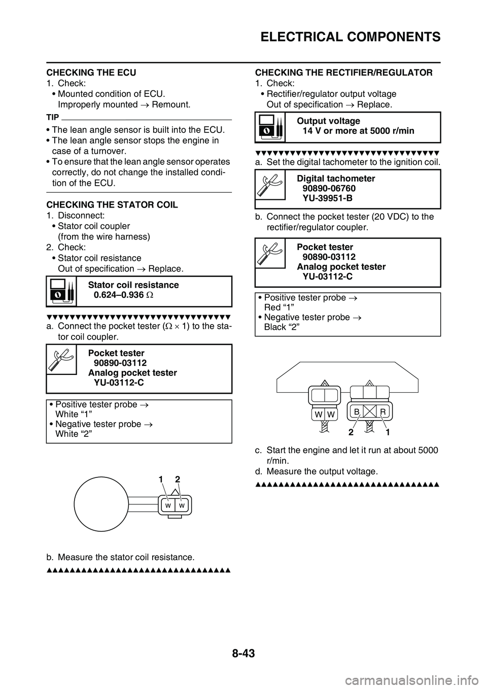
▼▼▼▼▼▼▼▼▼▼▼▼▼▼▼▼▼▼▼▼▼▼▼▼▼▼▼▼▼▼▼▼
a. Connect the pocket tester ( 1) to the sta-
tor coil coupler.
b. Measure the stator coil resistance.
▲▲▲▲▲▲▲▲▲▲▲▲▲▲▲▲▲▲▲▲▲▲▲▲▲▲▲▲▲▲▲▲
EAS1SL1341
CHECKING THE RECTIFIER/REGULATOR
1. Check:
• Rectifier/regulator output voltage
Out of specification Replace.
▼▼▼▼▼▼▼▼▼▼▼▼▼▼▼▼▼▼▼▼▼▼▼▼▼▼▼▼▼▼▼▼
a. Set the digital tachometer to the ignition coil.
b. Connect the pocket tester (20 VDC) to the
rectifier/regulator coupler.
c. Start the engine and let it run at about 5000
r/min.
d. Measure the output voltage.
▲▲▲▲▲▲▲▲▲▲▲▲▲▲▲▲▲▲▲▲▲▲▲▲▲▲▲▲▲▲▲▲
EAS1SL1342
Stator coil resistance
0.624–0.936
Pocket tester
90890-03112
Analog pocket tester
YU-03112-C
• Positive tester probe
White “1”
• Negative tester probe
White “2”
12
Output voltage
14 V or more at 5000 r/min
Digital tachometer
90890-06760
YU-39951-B
Pocket tester
90890-03112
Analog pocket tester
YU-03112-C
• Positive tester probe
Red “1”
• Negative tester probe
Black “2”
21
B
WWR
Page 334 of 360
ELECTRICAL COMPONENTS
8-44
CHECKING THE COOLANT TEMPERATURE
SENSOR
1. Remove:
• Coolant temperature sensorEWA14130
WARNING
• Handle the coolant temperature sensor
with special care.
• Never subject the coolant temperature
sensor to strong shocks. If the coolant
temperature sensor is dropped, replace it.
2. Check:
• Coolant temperature sensor resistance
Out of specification Replace.
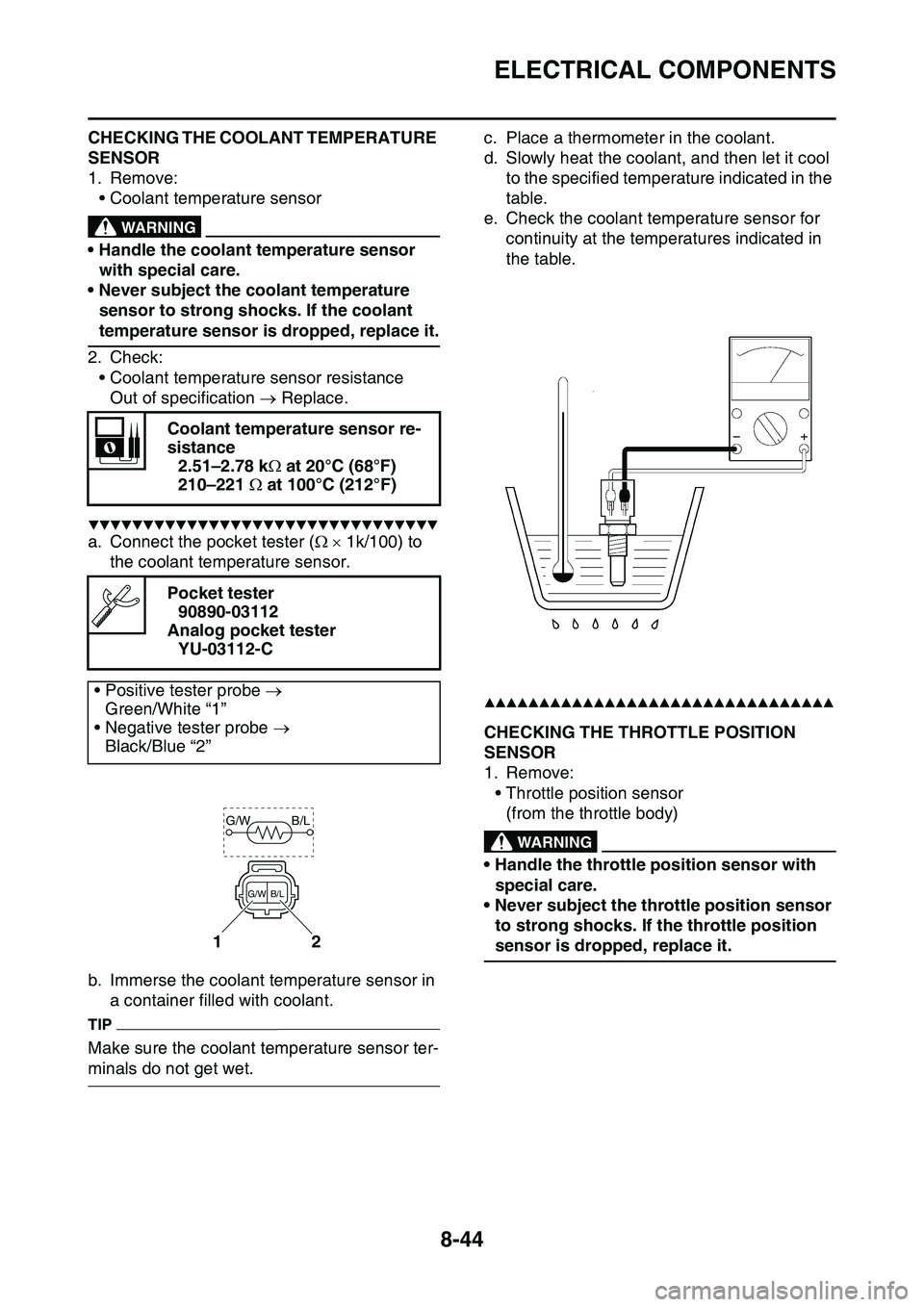
▼▼▼▼▼▼▼▼▼▼▼▼▼▼▼▼▼▼▼▼▼▼▼▼▼▼▼▼▼▼▼▼
a. Connect the pocket tester ( 1k/100) to
the coolant temperature sensor.
b. Immerse the coolant temperature sensor in
a container filled with coolant.
TIP
Make sure the coolant temperature sensor ter-
minals do not get wet.
c. Place a thermometer in the coolant.
d. Slowly heat the coolant, and then let it cool
to the specified temperature indicated in the
table.
e. Check the coolant temperature sensor for
continuity at the temperatures indicated in
the table.
▲▲▲▲▲▲▲▲▲▲▲▲▲▲▲▲▲▲▲▲▲▲▲▲▲▲▲▲▲▲▲▲
EAS1SL1343CHECKING THE THROTTLE POSITION
SENSOR
1. Remove:
• Throttle position sensor
(from the throttle body)EWA1DX1009
WARNING
• Handle the throttle position sensor with
special care.
• Never subject the throttle position sensor
to strong shocks. If the throttle position
sensor is dropped, replace it.
Coolant temperature sensor re-
sistance
2.51–2.78 k at 20°C (68°F)
210–221 at 100°C (212°F)
Pocket tester
90890-03112
Analog pocket tester
YU-03112-C
• Positive tester probe
Green/White “1”
• Negative tester probe
Black/Blue “2”
12
G/W B/L
B/L G/W
Page 335 of 360
ELECTRICAL COMPONENTS
8-45
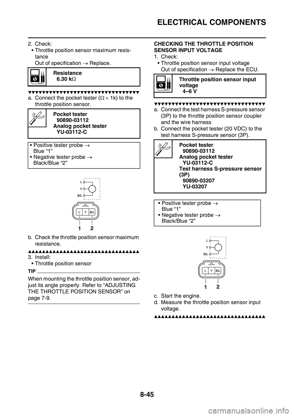
2. Check:
• Throttle position sensor maximum resis-
tance
Out of specification Replace.
▼▼▼▼▼▼▼▼▼▼▼▼▼▼▼▼▼▼▼▼▼▼▼▼▼▼▼▼▼▼▼▼
a. Connect the pocket tester ( 1k) to the
throttle position sensor.
b. Check the throttle position sensor maximum
resistance.
▲▲▲▲▲▲▲▲▲▲▲▲▲▲▲▲▲▲▲▲▲▲▲▲▲▲▲▲▲▲▲▲
3. Install:
• Throttle position sensor
TIP
When mounting the throttle position sensor, ad-
just its angle properly. Refer to “ADJUSTING
THE THROTTLE POSITION SENSOR” on
page 7-9.
EAS1SL1344
CHECKING THE THROTTLE POSITION
SENSOR INPUT VOLTAGE
1. Check:
• Throttle position sensor input voltage
Out of specification Replace the ECU.
▼▼▼▼▼▼▼▼▼▼▼▼▼▼▼▼▼▼▼▼▼▼▼▼▼▼▼▼▼▼▼▼
a. Connect the test harness S-pressure sensor
(3P) to the throttle position sensor coupler
and the wire harness
b. Connect the pocket tester (20 VDC) to the
test harness S-pressure sensor (3P).
c. Start the engine.
d. Measure the throttle position sensor input
voltage.
▲▲▲▲▲▲▲▲▲▲▲▲▲▲▲▲▲▲▲▲▲▲▲▲▲▲▲▲▲▲▲▲
EAS1SL1345
Resistance
6.30 k
Pocket tester
90890-03112
Analog pocket tester
YU-03112-C
• Positive tester probe
Blue “1”
• Negative tester probe
Black/Blue “2”
21
Throttle position sensor input
voltage
4–6 V
Pocket tester
90890-03112
Analog pocket tester
YU-03112-C
Test harness S-pressure sensor
(3P)
90890-03207
YU-03207
• Positive tester probe
Blue “1”
• Negative tester probe
Black/Blue “2”
21
Page 336 of 360
ELECTRICAL COMPONENTS
8-46
CHECKING THE INTAKE AIR PRESSURE
SENSOR
1. Check:
• Intake air pressure sensor output voltage
Out of specification Replace.
▼▼▼▼▼▼▼▼▼▼▼▼▼▼▼▼▼▼▼▼▼▼▼▼▼▼▼▼▼▼▼▼
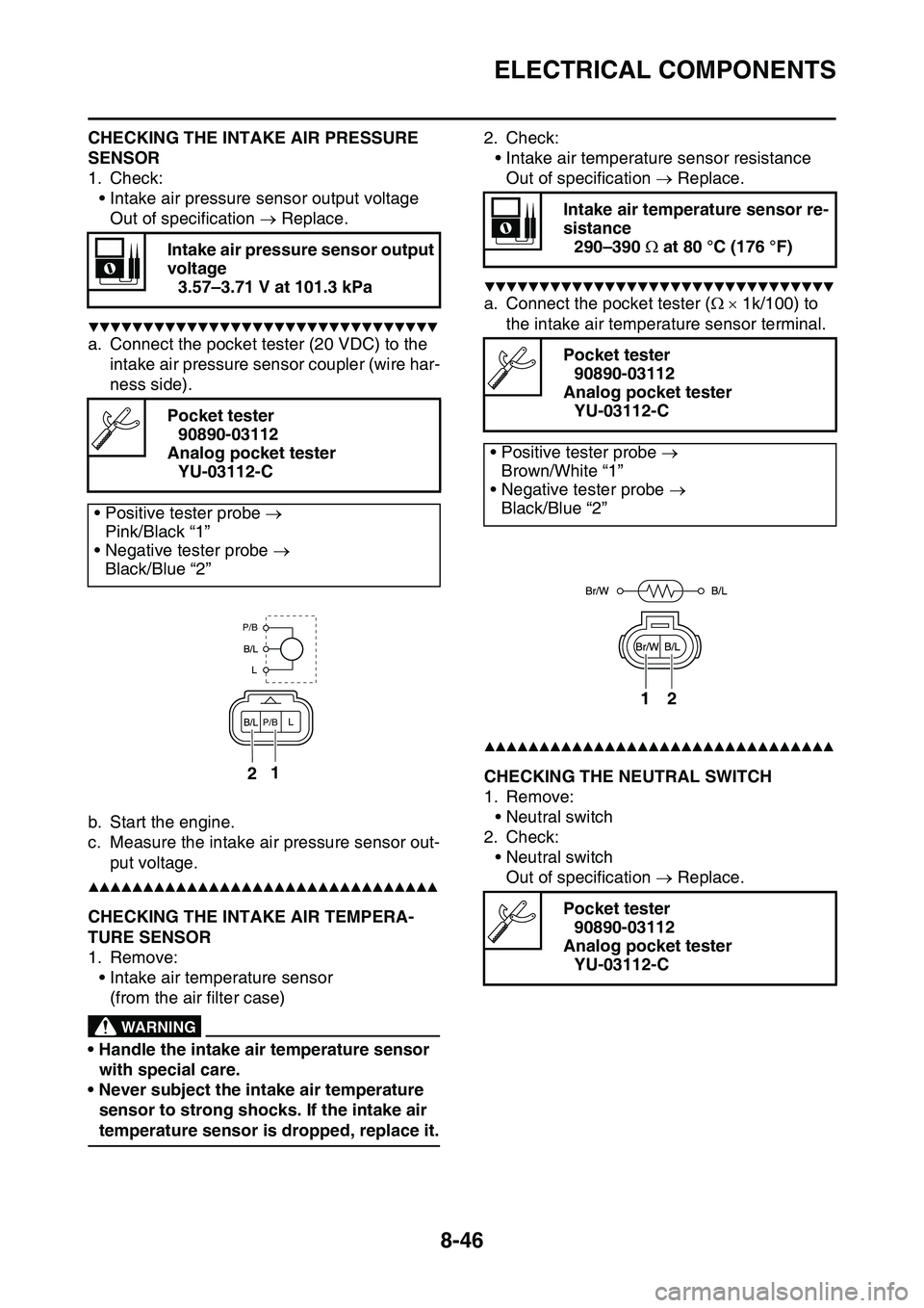
a. Connect the pocket tester (20 VDC) to the
intake air pressure sensor coupler (wire har
-
ness side).
b. Start the engine.
c. Measure the intake air pressure sensor out-
put voltage.
▲▲▲▲▲▲▲▲▲▲▲▲▲▲▲▲▲▲▲▲▲▲▲▲▲▲▲▲▲▲▲▲
EAS1SL1346CHECKING THE INTAKE AIR TEMPERA-
TURE SENSOR
1. Remove:
• Intake air temperature sensor
(from the air filter case)EWA1DX1010
WARNING
• Handle the intake air temperature sensor
with special care.
• Never subject the intake air temperature
sensor to strong shocks. If the intake air
temperature sensor is dropped, replace it.
2. Check:
• Intake air temperature sensor resistance
Out of specification Replace.
▼▼▼▼▼▼▼▼▼▼▼▼▼▼▼▼▼▼▼▼▼▼▼▼▼▼▼▼▼▼▼▼
a. Connect the pocket tester ( 1k/100) to
the intake air temperature sensor terminal.
▲▲▲▲▲▲▲▲▲▲▲▲▲▲▲▲▲▲▲▲▲▲▲▲▲▲▲▲▲▲▲▲
EAS1SL1347CHECKING THE NEUTRAL SWITCH
1. Remove:
• Neutral switch
2. Check:
• Neutral switch
Out of specification Replace.
Intake air pressure sensor output
voltage
3.57–3.71 V at 101.3 kPa
Pocket tester
90890-03112
Analog pocket tester
YU-03112-C
• Positive tester probe
Pink/Black “1”
• Negative tester probe
Black/Blue “2”
12
P/B
P/B
Intake air temperature sensor re-
sistance
290–390 at 80 °C (176 °F)
Pocket tester
90890-03112
Analog pocket tester
YU-03112-C
• Positive tester probe
Brown/White “1”
• Negative tester probe
Black/Blue “2”
Pocket tester
90890-03112
Analog pocket tester
YU-03112-C
12
Page 337 of 360
ELECTRICAL COMPONENTS
8-47
EAS1SL1348CHECKING THE FUEL INJECTOR
1. Remove:
• Fuel injector
Refer to “THROTTLE BODY” on page 7-5.
2. Check:
• Fuel injector resistance
Out of specification Replace.
▼▼▼▼▼▼▼▼▼▼▼▼▼▼▼▼▼▼▼▼▼▼▼▼▼▼▼▼▼▼▼▼
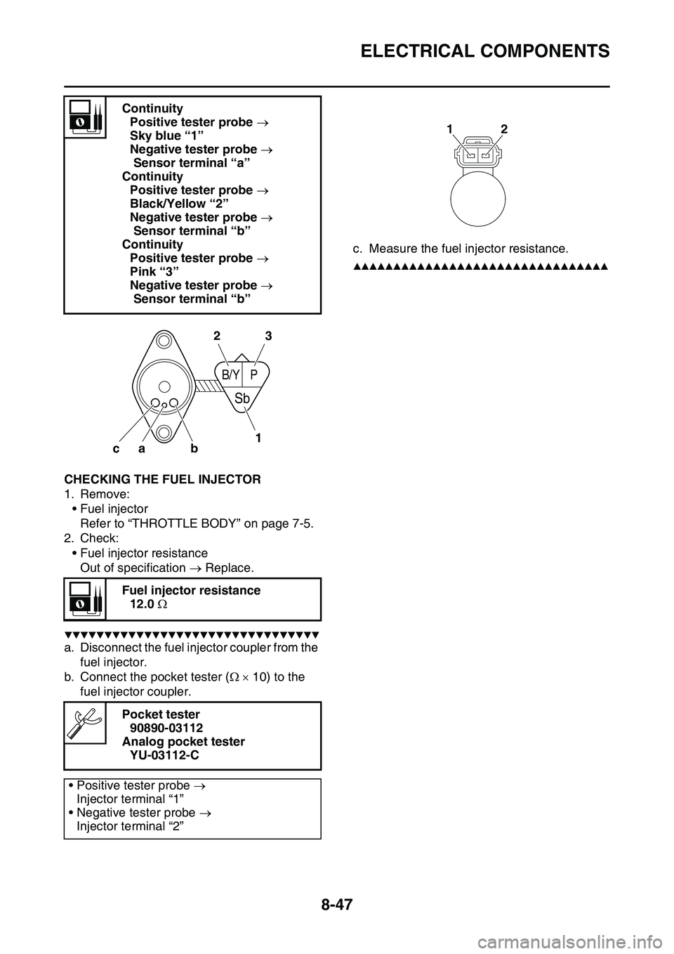
a. Disconnect the fuel injector coupler from the
fuel injector.
b. Connect the pocket tester ( 10) to the
fuel injector coupler.
c. Measure the fuel injector resistance.
▲▲▲▲▲▲▲▲▲▲▲▲▲▲▲▲▲▲▲▲▲▲▲▲▲▲▲▲▲▲▲▲
Continuity
Positive tester probe
Sky blue “1”
Negative tester probe
Sensor terminal “a”
Continuity
Positive tester probe
Black/Yellow “2”
Negative tester probe
Sensor terminal “b”
Continuity
Positive tester probe
Pink “3”
Negative tester probe
Sensor terminal “b”
Fuel injector resistance
12.0
Pocket tester
90890-03112
Analog pocket tester
YU-03112-C
• Positive tester probe
Injector terminal “1”
• Negative tester probe
Injector terminal “2”
b ca
B/YP
Sb
2
13
12
Page 338 of 360
ELECTRICAL COMPONENTS
8-48
Page 339 of 360
9
TROUBLE SHOOTING
TROUBLE SHOOTING..................................................................................... 9-1
GENERAL INFORMATION ........................................................................ 9-1
STARTING FAILURES ............................................................................... 9-1
INCORRECT ENGINE IDLING SPEED ..................................................... 9-1
POOR MEDIUM-AND-HIGH-SPEED PERFORMANCE ............................ 9-2
FAULTY GEAR SHIFTING ......................................................................... 9-2
SHIFT PEDAL DOES NOT MOVE ............................................................. 9-2
JUMPS OUT OF GEAR.............................................................................. 9-2
FAULTY CLUTCH ...................................................................................... 9-2
OVERHEATING ......................................................................................... 9-2
OVERCOOLING ......................................................................................... 9-3
POOR BRAKING PERFORMANCE ........................................................... 9-3
FAULTY FRONT FORK LEGS ................................................................... 9-3
UNSTABLE HANDLING ............................................................................. 9-3
LIST OF SELF-DIAGNOSTIC AND FAIL-SAFE ACTIONS............................. 9-4
Page 340 of 360
TROUBLE SHOOTING
9-1
EAS1SL1349
TROUBLE SHOOTING
EAS1SL1350GENERAL INFORMATION
TIP
The following guide for troubleshooting does
not cover all the possible causes of trouble. It
should be helpful, however, as a guide to basic
troubleshooting. Refer to the relative procedure
in this manual for checks, adjustments, and re
-
placement of parts.
EAS1SL1351STARTING FAILURES
Engine
1. Cylinder and cylinder head
• Loose spark plug
• Loose cylinder head or cylinder
• Damaged cylinder head gasket
• Damaged cylinder gasket
• Worn or damaged cylinder
• Incorrect valve clearance
• Improperly sealed valve
• Incorrect valve-to-valve-seat contact
• Incorrect valve timing
• Faulty valve spring
• Seized valve
2. Piston and piston ring(s)
• Improperly installed piston ring
• Damaged, worn or fatigued piston ring
• Seized piston ring
• Seized or damaged piston
3. Air filter
• Improperly installed air filter
• Clogged air filter element
4. Crankcase and crankshaft
• Improperly assembled crankcase
• Seized crankshaft
Fuel system
1. Fuel tank
• Empty fuel tank
• Clogged fuel tank breather hose
• Deteriorated or contaminated fuel
• Clogged or damaged fuel hose
2. Fuel pump
• Faulty fuel pump
3. Throttle body
• Deteriorated or contaminated fuel
• Sucked-in air
Electrical system
1. Spark plug
• Incorrect spark plug gap
• Incorrect spark plug heat range
• Fouled spark plug
• Worn or damaged electrode
• Worn or damaged insulator
2. Ignition coil
• Cracked or broken ignition coil body
• Broken or shorted primary or secondary
coils
3. Ignition system
• Faulty ECU
• Faulty crankshaft position sensor
• Broken generator rotor woodruff key
4. Switches and wiring
• Faulty ECU
• Faulty engine stop switch
• Broken or shorted wiring
• Faulty neutral switch
• Improperly grounded circuit
• Loose connections
EAS1SL1352INCORRECT ENGINE IDLING SPEED
Engine
1. Cylinder and cylinder head
• Incorrect valve clearance
• Damaged valve train components
2. Air filter
• Clogged air filter element
Fuel system
1. Throttle body
• Damaged or loose throttle body joint
• Improperly synchronized throttle bodies
• Improper throttle cable free play
• Flooded throttle body
Electrical system
1. Spark plug
• Incorrect spark plug gap
• Incorrect spark plug heat range
• Fouled spark plug
• Worn or damaged electrode
• Worn or damaged insulator
• Faulty spark plug cap
2. Ignition coil
• Broken or shorted primary or secondary
coils
• Cracked or broken ignition coil