engine YAMAHA YZ450F 2014 Repair Manual
[x] Cancel search | Manufacturer: YAMAHA, Model Year: 2014, Model line: YZ450F, Model: YAMAHA YZ450F 2014Pages: 360, PDF Size: 11.76 MB
Page 193 of 360
5
ENGINE
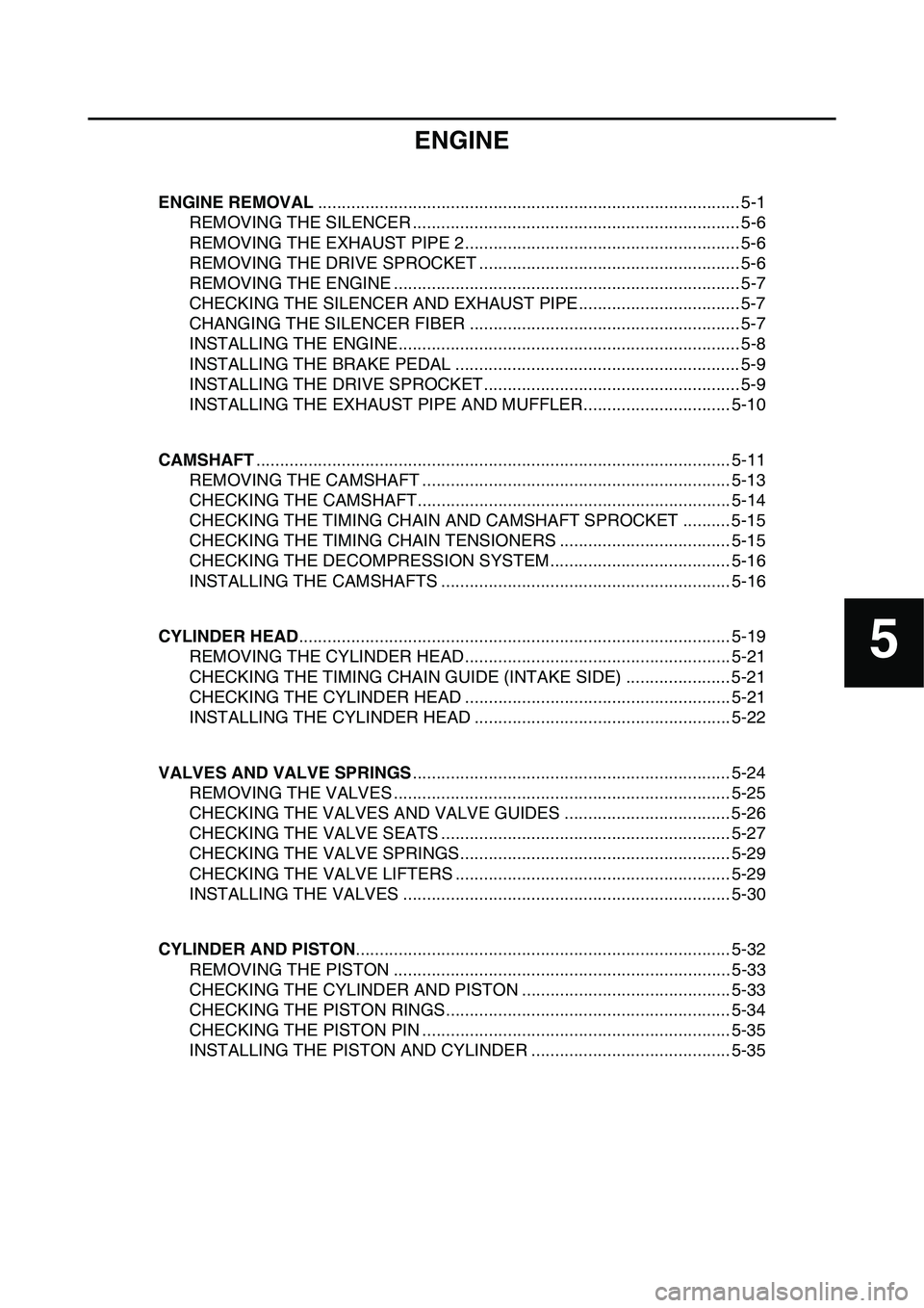
ENGINE REMOVAL......................................................................................... 5-1
REMOVING THE SILENCER ..................................................................... 5-6
REMOVING THE EXHAUST PIPE 2.......................................................... 5-6
REMOVING THE DRIVE SPROCKET ....................................................... 5-6
REMOVING THE ENGINE ......................................................................... 5-7
CHECKING THE SILENCER AND EXHAUST PIPE.................................. 5-7
CHANGING THE SILENCER FIBER ......................................................... 5-7
INSTALLING THE ENGINE........................................................................ 5-8
INSTALLING THE BRAKE PEDAL ............................................................ 5-9
INSTALLING THE DRIVE SPROCKET...................................................... 5-9
INSTALLING THE EXHAUST PIPE AND MUFFLER............................... 5-10
CAMSHAFT.................................................................................................... 5-11
REMOVING THE CAMSHAFT ................................................................. 5-13
CHECKING THE CAMSHAFT.................................................................. 5-14
CHECKING THE TIMING CHAIN AND CAMSHAFT SPROCKET .......... 5-15
CHECKING THE TIMING CHAIN TENSIONERS .................................... 5-15
CHECKING THE DECOMPRESSION SYSTEM...................................... 5-16
INSTALLING THE CAMSHAFTS ............................................................. 5-16
CYLINDER HEAD........................................................................................... 5-19
REMOVING THE CYLINDER HEAD........................................................ 5-21
CHECKING THE TIMING CHAIN GUIDE (INTAKE SIDE) ...................... 5-21
CHECKING THE CYLINDER HEAD ........................................................ 5-21
INSTALLING THE CYLINDER HEAD ...................................................... 5-22
VALVES AND VALVE SPRINGS................................................................... 5-24
REMOVING THE VALVES ....................................................................... 5-25
CHECKING THE VALVES AND VALVE GUIDES ................................... 5-26
CHECKING THE VALVE SEATS ............................................................. 5-27
CHECKING THE VALVE SPRINGS......................................................... 5-29
CHECKING THE VALVE LIFTERS .......................................................... 5-29
INSTALLING THE VALVES ..................................................................... 5-30
CYLINDER AND PISTON............................................................................... 5-32
REMOVING THE PISTON ....................................................................... 5-33
CHECKING THE CYLINDER AND PISTON ............................................ 5-33
CHECKING THE PISTON RINGS............................................................ 5-34
CHECKING THE PISTON PIN ................................................................. 5-35
INSTALLING THE PISTON AND CYLINDER .......................................... 5-35
Page 196 of 360
ENGINE REMOVAL
5-1
EAS1SL1195
TIP
This section is intended for those who have basic knowledge and skill concerning the servicing of
Yamaha motorcycles (e.g., Yamaha dealers, service engineers, etc.). Those who have little knowl
-
edge and skill concerning servicing are requested not to undertake inspection, adjustment, disas-
sembly, or reassembly only by reference to this manual. It may lead to servicing trouble and
mechanical damage.
EAS1SL1196
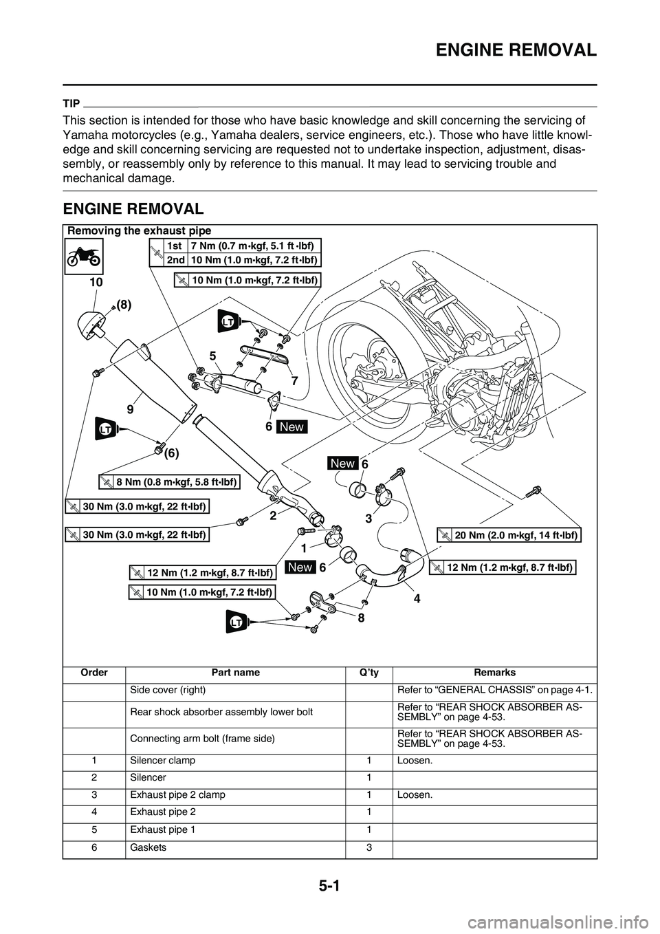
ENGINE REMOVAL
Removing the exhaust pipe
OrderPart nameQ’tyRemarks
Side cover (right)Refer to “GENERAL CHASSIS” on page 4-1.
Rear shock absorber assembly lower boltRefer to “REAR SHOCK ABSORBER AS-SEMBLY” on page 4-53.
Connecting arm bolt (frame side)Refer to “REAR SHOCK ABSORBER AS-SEMBLY” on page 4-53.
1Silencer clamp1Loosen.
2Silencer1
3Exhaust pipe 2 clamp1Loosen.
4Exhaust pipe 21
5Exhaust pipe 11
6Gaskets3
10
5
9
2 6
1
66
3
84 7 (8)
(6)
30 Nm (3.0 mkgf, 22 ftIbf)T.R.
30 Nm (3.0 mkgf, 22 ftIbf)T.R.
8 Nm (0.8 mkgf, 5.8 ftIbf)T.R.
10 Nm (1.0 mkgf, 7.2 ftIbf)T.R.
New
New
10 Nm (1.0 mkgf, 7.2 ftIbf)T.R.
12 Nm (1.2 mkgf, 8.7 ftIbf)T.R.12 Nm (1.2 mkgf, 8.7 ftIbf)T.R.
20 Nm (2.0 mkgf, 14 ftIbf)T.R.
New
1st 7 Nm (0.7 mkgf, 5.1 ftlbf)
2nd 10 Nm (1.0 m
kgf, 7.2 ftlbf)T.
R
.
LT
LT
LT
Page 197 of 360
ENGINE REMOVAL
5-2
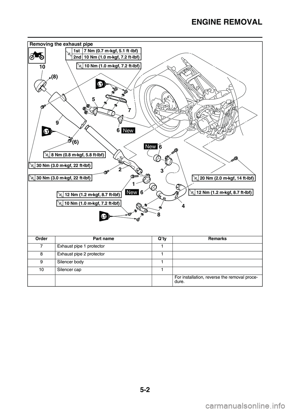
7Exhaust pipe 1 protector1
8Exhaust pipe 2 protector1
9Silencer body1
10Silencer cap1
For installation, reverse the removal proce-dure.
Removing the exhaust pipe
Order Part name Q’ty Remarks
10
5
9
2 6
1
66
3
84 7 (8)
(6)
30 Nm (3.0 mkgf, 22 ftIbf)T.R.
30 Nm (3.0 mkgf, 22 ftIbf)T.
R
.
8 Nm (0.8 mkgf, 5.8 ftIbf)T.R.
10 Nm (1.0 mkgf, 7.2 ftIbf)T.R.
New
New
10 Nm (1.0 mkgf, 7.2 ftIbf)T.R.
12 Nm (1.2 mkgf, 8.7 ftIbf)T.R.12 Nm (1.2 mkgf, 8.7 ftIbf)T.R.
20 Nm (2.0 mkgf, 14 ftIbf)T.R.
New
1st 7 Nm (0.7 mkgf, 5.1 ftlbf)
2nd 10 Nm (1.0 m
kgf, 7.2 ftlbf)T.
R
.
LT
LT
LT
Page 198 of 360
ENGINE REMOVAL
5-3
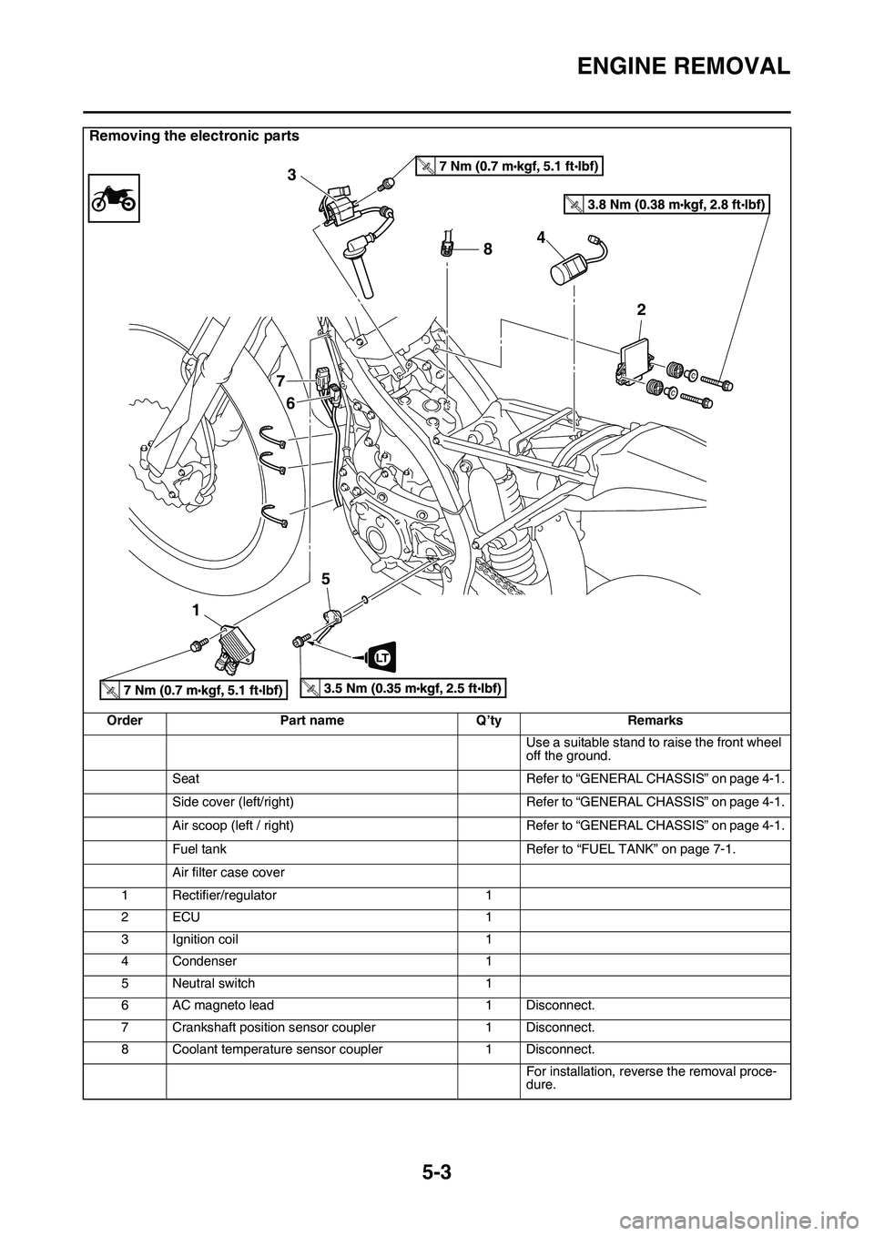
Removing the electronic parts
OrderPart nameQ’tyRemarks
Use a suitable stand to raise the front wheel
off the ground.
SeatRefer to “GENERAL CHASSIS” on page 4-1.
Side cover (left/right)Refer to “GENERAL CHASSIS” on page 4-1.
Air scoop (left / right)Refer to “GENERAL CHASSIS” on page 4-1.
Fuel tankRefer to “FUEL TANK” on page 7-1.
Air filter case cover
1Rectifier/regulator1
2ECU1
3Ignition coil1
4Condenser1
5Neutral switch1
6AC magneto lead1Disconnect.
7Crankshaft position sensor coupler1Disconnect.
8Coolant temperature sensor coupler1Disconnect.
For installation, reverse the removal proce-dure.
T.R.
T.R.
T.R.T.R.
8 3
7
6
154
2
LT
Page 199 of 360
ENGINE REMOVAL
5-4
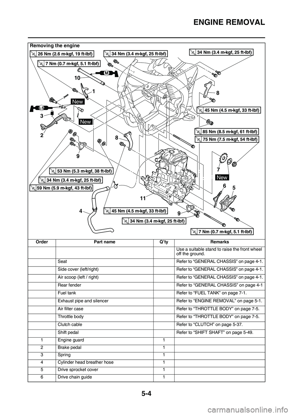
Removing the engine
OrderPart name Q’tyRemarks
Use a suitable stand to raise the front wheel
off the ground.
Seat Refer to “GENERAL CHASSIS” on page 4-1.
Side cover (left/right) Refer to “GENERAL CHASSIS” on page 4-1.
Air scoop (left / right) Refer to “GENERAL CHASSIS” on page 4-1.
Rear fender Refer to “GENERAL CHASSIS” on page 4-1
Fuel tank Refer to “FUEL TANK” on page 7-1.
Exhaust pipe and silencer Refer to “ENGINE REMOVAL” on page 5-1.
Air filter case Refer to “THROTTLE BODY” on page 7-5.
Throttle body Refer to “THROTTLE BODY” on page 7-5.
Clutch cable Refer to “CLUTCH” on page 5-37.
Shift pedal Refer to “SHIFT SHAFT” on page 5-49.
1 Engine guard 1
2 Brake pedal 1
3Spring 1
4 Cylinder head breather hose 1
5 Drive sprocket cover 1
6 Drive chain guide 1
New
New
LS
M
8
8
76
11
4 5
New
1
10
3 2
Page 200 of 360
ENGINE REMOVAL
5-5
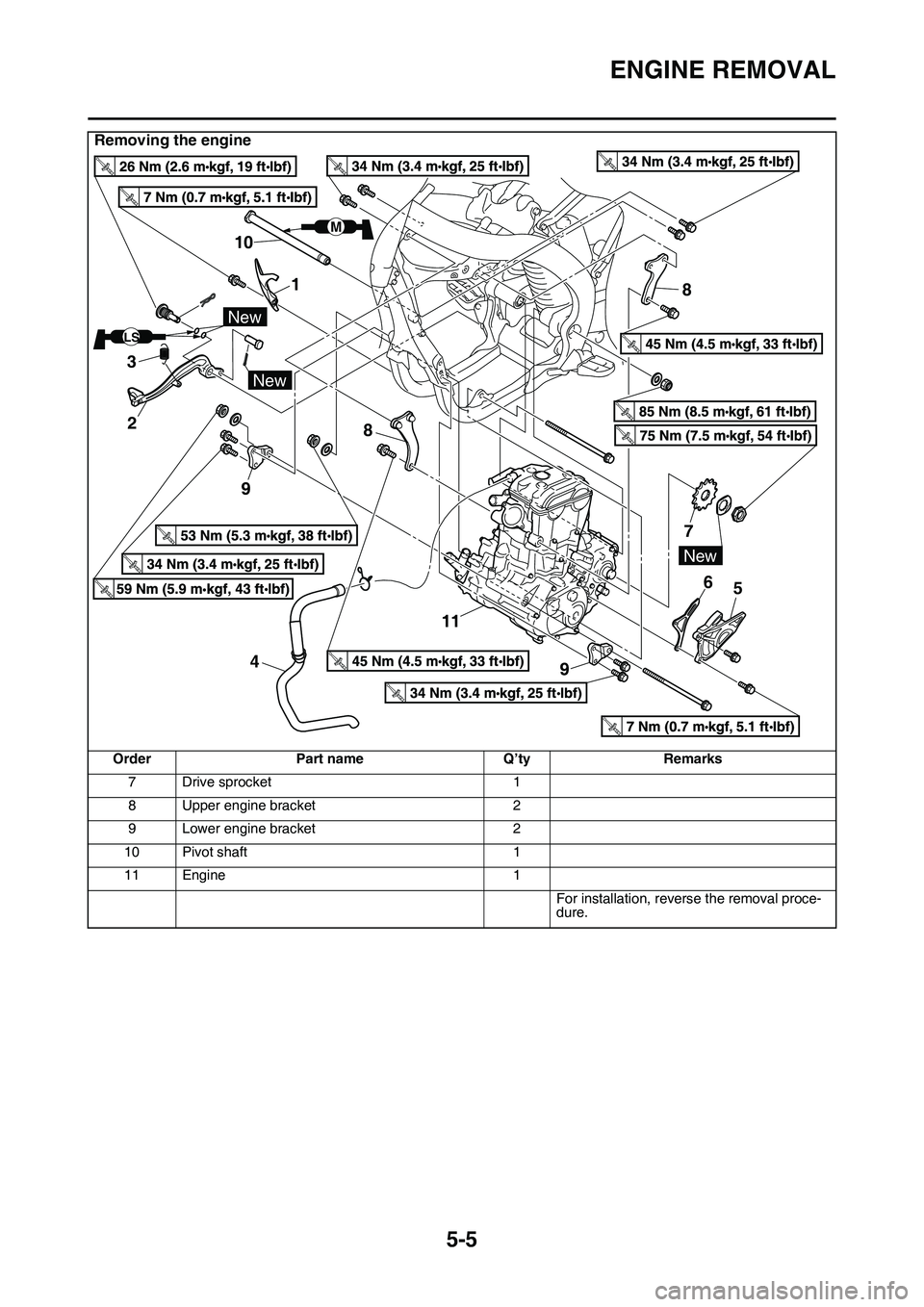
7 Drive sprocket1
8 Upper engine bracket 2
9 Lower engine bracket 2
10 Pivot shaft 1
11 Engine 1
For installation, reverse the removal proce-
dure.
Removing the engine
Order Part name Q’tyRemarks
New
New
LS
M
8
8
76
11
4 5
New
1
10
3 2
Page 201 of 360
ENGINE REMOVAL
5-6
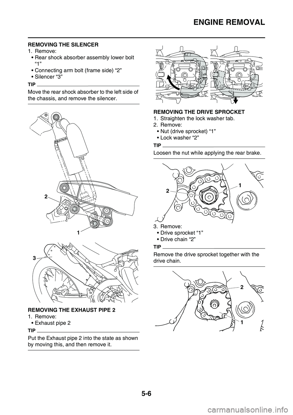
EAS1SL1197REMOVING THE SILENCER
1. Remove:
• Rear shock absorber assembly lower bolt
“1”
• Connecting arm bolt (frame side) “2”
• Silencer “3”
TIP
Move the rear shock absorber to the left side of
the chassis, and remove the silencer.
EAS1SL1198REMOVING THE EXHAUST PIPE 2
1. Remove:
• Exhaust pipe 2
TIP
Put the Exhaust pipe 2 into the state as shown
by moving this, and then remove it.
EAS1SL1199REMOVING THE DRIVE SPROCKET
1. Straighten the lock washer tab.
2. Remove:
• Nut (drive sprocket) “1”
• Lock washer “2”
TIP
Loosen the nut while applying the rear brake.
3. Remove:
• Drive sprocket “1”
• Drive chain “2”
TIP
Remove the drive sprocket together with the
drive chain.
EAS1SL1200
1 2
3
Page 202 of 360
ENGINE REMOVAL
5-7
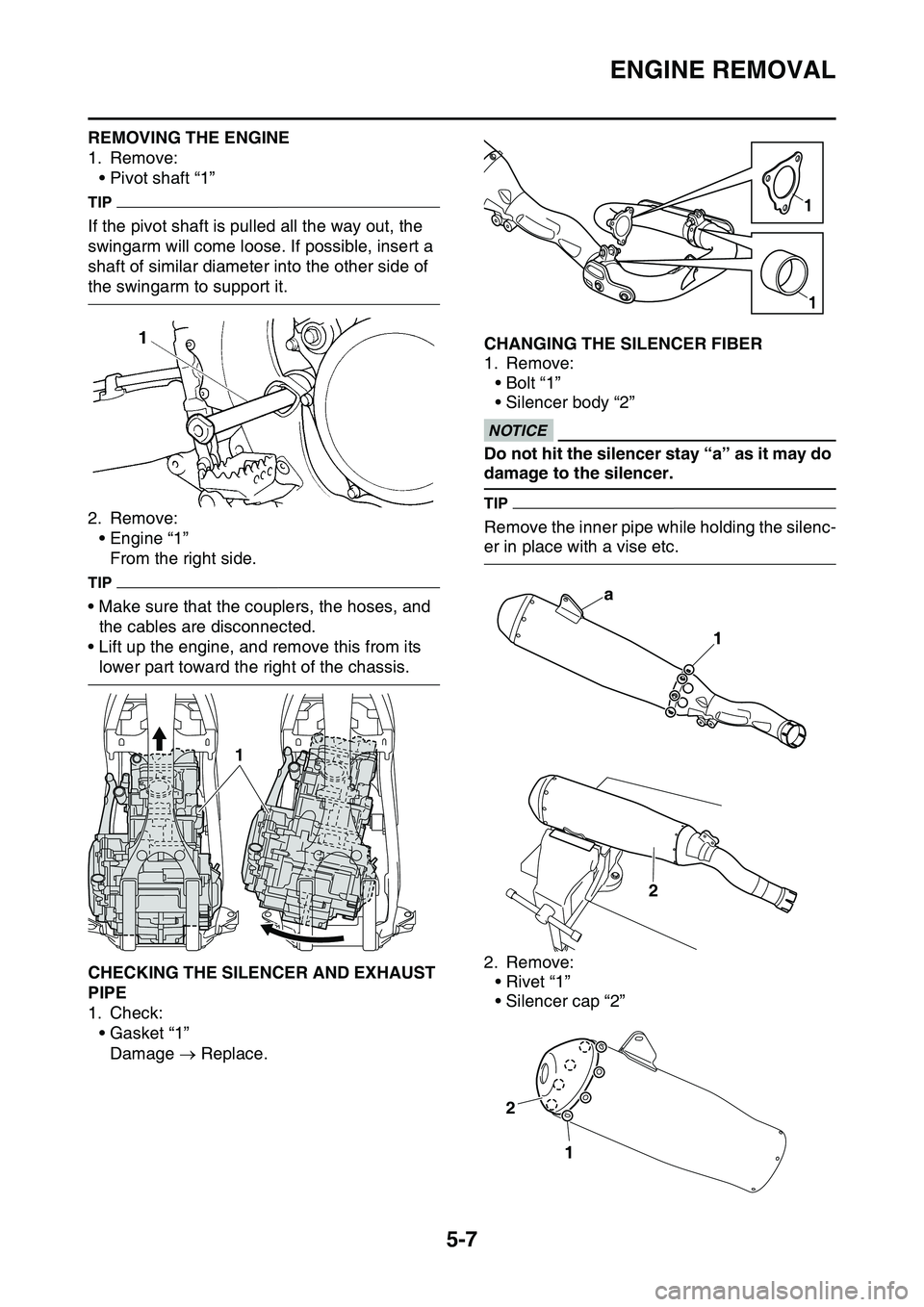
REMOVING THE ENGINE
1. Remove:
• Pivot shaft “1”
TIP
If the pivot shaft is pulled all the way out, the
swingarm will come loose. If possible, insert a
shaft of similar diameter into the other side of
the swingarm to support it.
2. Remove:
• Engine “1”
From the right side.
TIP
• Make sure that the couplers, the hoses, and
the cables are disconnected.
• Lift up the engine, and remove this from its
lower part toward the right of the chassis.
EAS1SL1201CHECKING THE SILENCER AND EXHAUST
PIPE
1. Check:
•Gasket “1”
Damage Replace.
EAS1SL1202CHANGING THE SILENCER FIBER
1. Remove:
•Bolt “1”
• Silencer body “2”ECA33DD026
NOTICE
Do not hit the silencer stay “a” as it may do
damage to the silencer.
TIP
Remove the inner pipe while holding the silenc-
er in place with a vise etc.
2. Remove:
•Rivet “1”
• Silencer cap “2”
1
1
1
a
1
2
2
1
Page 203 of 360
ENGINE REMOVAL
5-8
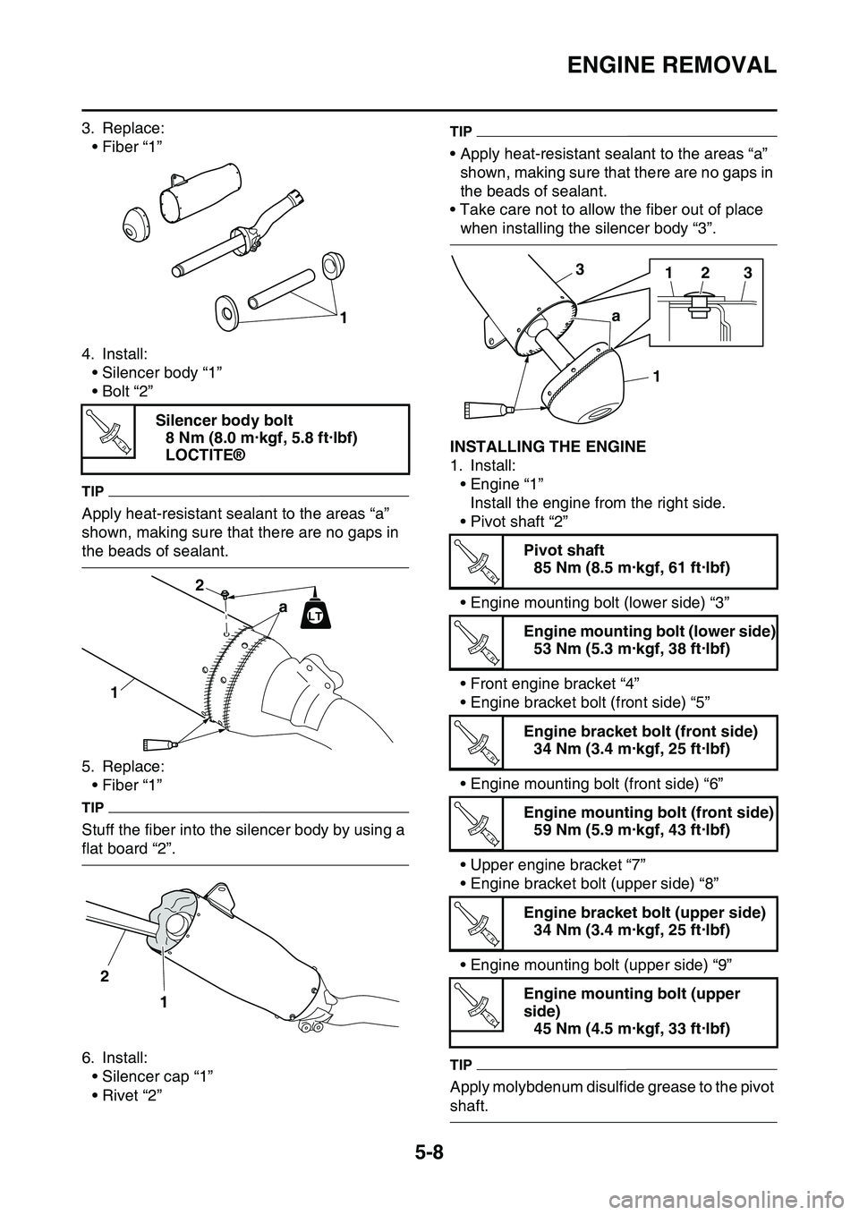
3. Replace:• Fiber “1”
4. Install: • Silencer body “1”
•Bolt “2”
TIP
Apply heat-resistant sealant to the areas “a”
shown, making sure that there are no gaps in
the beads of sealant.
5. Replace:• Fiber “1”
TIP
Stuff the fiber into the silencer body by using a
flat board “2”.
6. Install:• Silencer cap “1”
•Rivet “2”
TIP
• Apply heat-resistant sealant to the areas “a” shown, making sure that there are no gaps in
the beads of sealant.
• Take care not to allow the fiber out of place
when installing the silencer body “3”.
EAS1SL1203INSTALLING THE ENGINE
1. Install: • Engine “1”Install the engine from the right side.
• Pivot shaft “2”
• Engine mounting bolt (lower side) “3”
• Front engine bracket “4”
• Engine bracket bolt (front side) “5”
• Engine mounting bolt (front side) “6”
• Upper engine bracket “7”
• Engine bracket bolt (upper side) “8”
• Engine mounting bolt (upper side) “9”
TIP
Apply molybdenum disulfide grease to the pivot
shaft.
Silencer body bolt
8 Nm (8.0 m·kgf, 5.8 ft·lbf)
LOCTITE®
1
T R..
a
1 2LT
2
1
Pivot shaft85 Nm (8.5 m·kgf, 61 ft·lbf)
Engine mounting bolt (lower side) 53 Nm (5.3 m·kgf, 38 ft·lbf)
Engine bracket bolt (front side) 34 Nm (3.4 m·kgf, 25 ft·lbf)
Engine mounting bolt (front side) 59 Nm (5.9 m·kgf, 43 ft·lbf)
Engine bracket bolt (upper side) 34 Nm (3.4 m·kgf, 25 ft·lbf)
Engine mounting bolt (upper
side) 45 Nm (4.5 m·kgf, 33 ft·lbf)
1
1
a233
T R..
T R..
T R..
T R..
T R..
T R..
Page 204 of 360
ENGINE REMOVAL
5-9
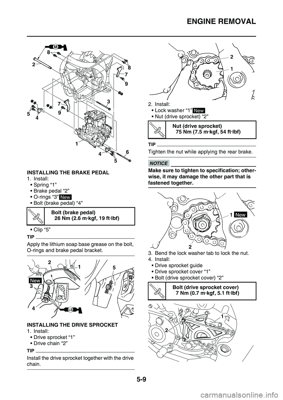
EAS1SL1204INSTALLING THE BRAKE PEDAL
1. Install:
• Spring “1”
• Brake pedal “2”
• O-rings “3”
• Bolt (brake pedal) “4”
•Clip “5”
TIP
Apply the lithium soap base grease on the bolt,
O-rings and brake pedal bracket.
EAS1SL1205INSTALLING THE DRIVE SPROCKET
1. Install:
• Drive sprocket “1”
• Drive chain “2”
TIP
Install the drive sprocket together with the drive
chain.
2. Install:
• Lock washer “1”
• Nut (drive sprocket) “2”
TIP
Tighten the nut while applying the rear brake.
ECA33DD040
NOTICE
Make sure to tighten to specification; other-
wise, it may damage the other part that is
fastened together.
3. Bend the lock washer tab to lock the nut.
4. Install:
• Drive sprocket guide
• Drive sprocket cover “1”
• Bolt (drive sprocket cover) “2”
Bolt (brake pedal)
26 Nm (2.6 m·kgf, 19 ft·lbf)
M
78
9
9 8
7
4 1
2
43
5
56
New
T R..
1 2
3
45
LS
Nut (drive sprocket)
75 Nm (7.5 m·kgf, 54 ft·lbf)
Bolt (drive sprocket cover)
7 Nm (0.7 m·kgf, 5.1 ft·lbf)
New
T R..
T R..
21