ECU YAMAHA YZ450F 2014 Owners Manual
[x] Cancel search | Manufacturer: YAMAHA, Model Year: 2014, Model line: YZ450F, Model: YAMAHA YZ450F 2014Pages: 360, PDF Size: 11.76 MB
Page 7 of 360
EAS1SL1005
SAFETY INFORMATION
THIS MACHINE IS DESIGNED STRICTLY FOR COMPETITION USE, ONLY ON A CLOSED
COURSE. It is illegal for this machine to be operated on any public street, road, or highway. Off-road
use on public lands may also be illegal. Please check local regulations before riding.
• THIS MACHINE IS TO BE OPERATED BY AN EXPERIENCED RIDER ONLY.
Do not attempt to operate this machine at maximum power until you are totally familiar with its char-
acteristics.
• THIS MACHINE IS DESIGNED TO BE RIDDEN BY THE OPERATOR ONLY.
Do not carry passengers on this machine.
• ALWAYS WEAR PROTECTIVE APPAREL.
When operating this machine, always wear an approved helmet with goggles or a face shield. Also
wear heavy boots, gloves, and protective clothing. Always wear proper fitting clothing that will not
be caught in any of the moving parts or controls of the machine.
• ALWAYS MAINTAIN YOUR MACHINE IN PROPER WORKING ORDER.
For safety and reliability, the machine must be properly maintained. Always perform the pre-oper-
ation checks indicated in this manual.
Correcting a mechanical problem before you ride may prevent an accident.
• GASOLINE IS HIGHLY FLAMMABLE.
Always turn off the engine while refueling. Take care to not spill any gasoline on the engine or ex-
haust system. Never refuel in the vicinity of an open flame, or while smoking.
• GASOLINE CAN CAUSE INJURY.
If you should swallow some gasoline, inhale excess gasoline vapors, or allow any gasoline to get
into your eyes, contact a doctor immediately. If any gasoline spills onto your skin or clothing, imme
-
diately wash skin areas with soap and water, and change your clothes.
• ONLY OPERATE THE MACHINE IN AN AREA WITH ADEQUATE VENTILATION.
Never start the engine or let it run for any length of time in an enclosed area. Exhaust fumes are
poisonous. These fumes contain carbon monoxide, which by itself is odorless and colorless. Car
-
bon monoxide is a dangerous gas which can cause unconsciousness or can be lethal.
• PARK THE MACHINE CAREFULLY; TURN OFF THE ENGINE.
Always turn off the engine if you are going to leave the machine. Do not park the machine on a slope
or soft ground as it may fall over.
• THE ENGINE, EXHAUST PIPE, MUFFLER, AND OIL TANK WILL BE VERY HOT AFTER THE EN-
GINE HAS BEEN RUN.
Be careful not to touch them or to allow any clothing item to contact them during inspection or repair.
• PROPERLY SECURE THE MACHINE BEFORE TRANSPORTING IT.
For safety, drain the gasoline from the fuel tank before transporting the vehicle.
Page 20 of 360
FEATURES
1-6
EAS20170
FEATURES
EAS1SL1014OUTLINE OF THE FI SYSTEM
The main function of a fuel supply system is to provide fuel to the combustion chamber at the opti-
mum air-fuel ratio in accordance with the engine operating conditions and the atmospheric tempera-
ture. In the conventional carburetor system, the air-fuel ratio of the mixture to be supplied to the
combustion chamber is determined by the amount of intake air and fuel that is measured on the basis
of the jets to be used in the carburetor.
Despite the same amount of intake air, the fuel amount requirement varies with the engine operating
conditions (acceleration, deceleration, and operation under a heavy load). The carburetor that mea
-
sures fuel through the use of jets are provided with various auxiliary devices, so that the optimum air
fuel ratio can be obtained to accommodate frequent changes in the operating conditions of the en
-
gine. This model has adopted an electronically controlled fuel injection (FI) system, in place of the
conventional carburetor system. This system can obtain the optimum air-fuel ratio required by the
engine at all times by using a microprocessor that regulates the fuel injection amount according to
the engine operating conditions detected by various sensors.
EAS1SL1015
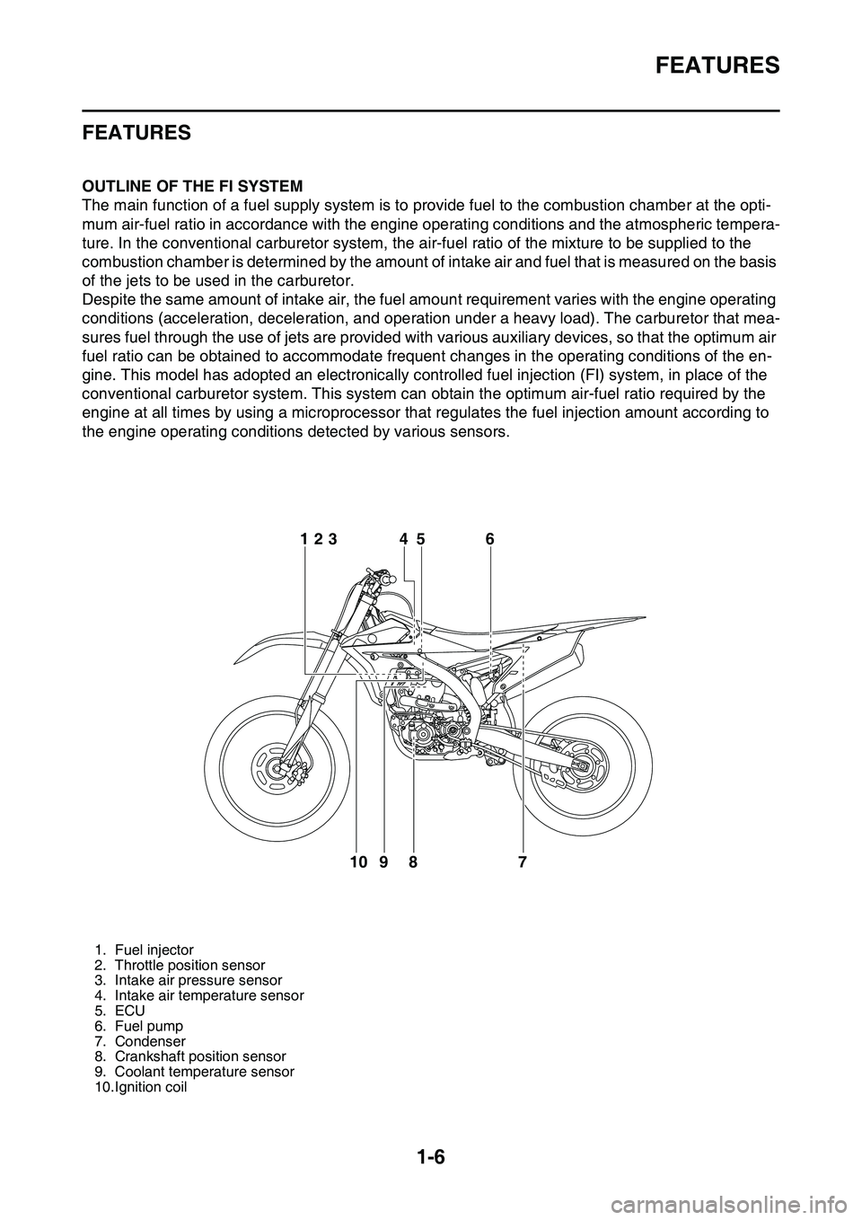
1. Fuel injector
2. Throttle position sensor
3. Intake air pressure sensor
4. Intake air temperature sensor
5. ECU
6. Fuel pump
7. Condenser
8. Crankshaft position sensor
9. Coolant temperature sensor
10.Ignition coil
6
7 8 95 4 123
10
Page 21 of 360
FEATURES
1-7
FI SYSTEM
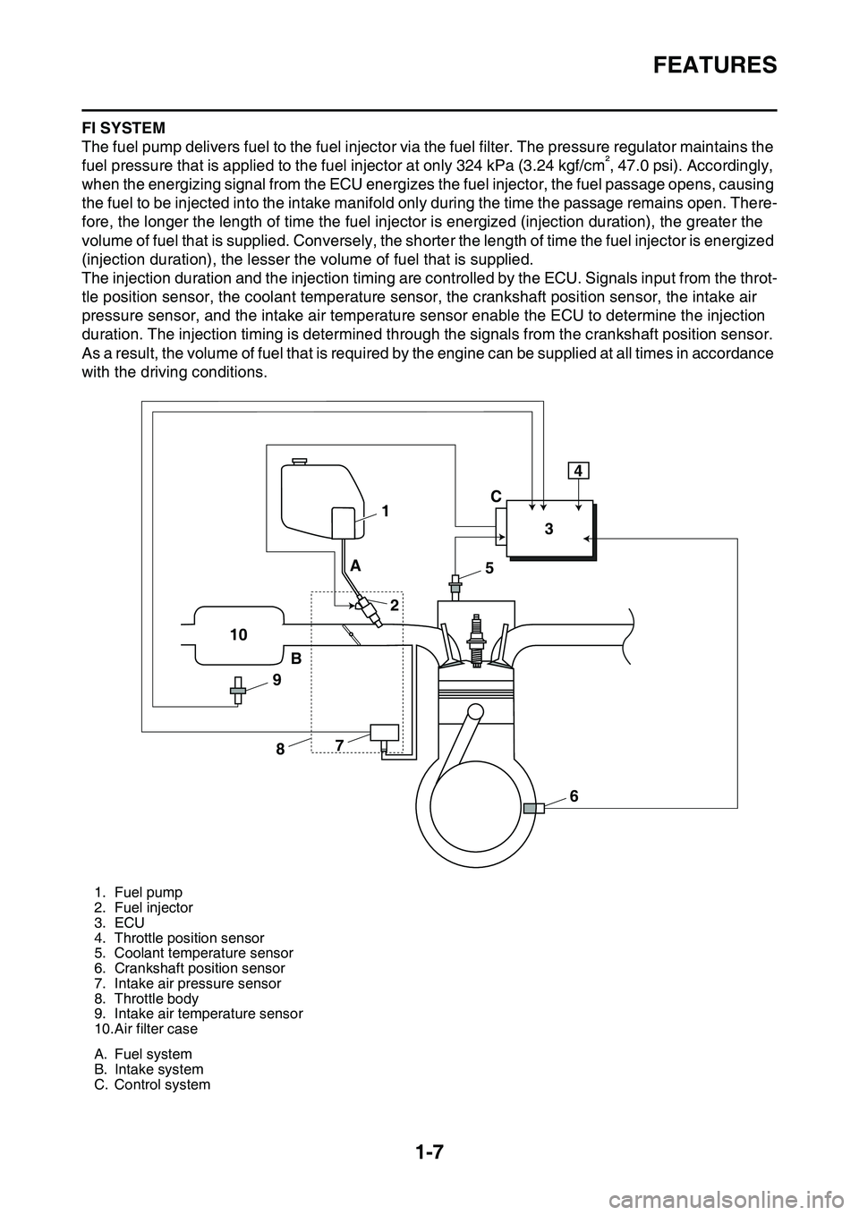
The fuel pump delivers fuel to the fuel injector via the fuel filter. The pressure regulator maintains the
fuel pressure that is applied to the fuel injector at only 324 kPa (3.24 kgf/cm², 47.0 psi). Accordingly,
when the energizing signal from the ECU energizes the fuel injector, the fuel passage opens, causing
the fuel to be injected into the intake manifold only during the time the passage remains open. There
-
fore, the longer the length of time the fuel injector is energized (injection duration), the greater the
volume of fuel that is supplied. Conversely, the shorter the length of time the fuel injector is energized
(injection duration), the lesser the volume of fuel that is supplied.
The injection duration and the injection timing are controlled by the ECU. Signals input from the throt-
tle position sensor, the coolant temperature sensor, the crankshaft position sensor, the intake air
pressure sensor, and the intake air temperature sensor enable the ECU to determine the injection
duration. The injection timing is determined through the signals from the crankshaft position sensor.
As a result, the volume of fuel that is required by the engine can be supplied at all times in accordance
with the driving conditions.
1. Fuel pump
2. Fuel injector
3. ECU
4. Throttle position sensor
5. Coolant temperature sensor
6. Crankshaft position sensor
7. Intake air pressure sensor
8. Throttle body
9. Intake air temperature sensor
10.Air filter case
A. Fuel system
B. Intake system
C. Control system
1
234
5
6 7
8 9 10A
BC
Page 27 of 360
BASIC SERVICE INFORMATION
1-13
ECA16790
NOTICE
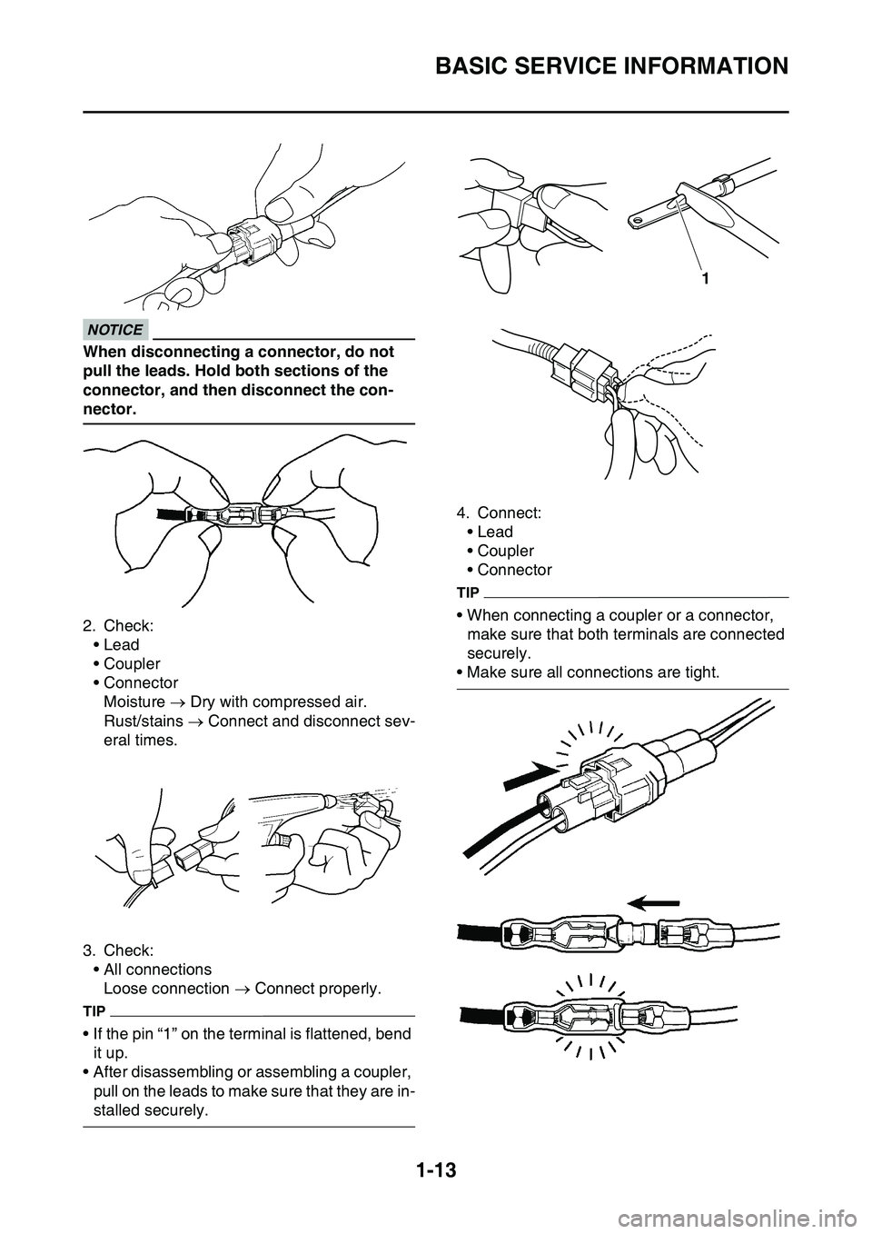
When disconnecting a connector, do not
pull the leads. Hold both sections of the
connector, and then disconnect the con
-
nector.
2. Check:
• Lead
• Coupler
• Connector
Moisture Dry with compressed air.
Rust/stains Connect and disconnect sev-
eral times.
3. Check:
• All connections
Loose connection Connect properly.
TIP
• If the pin “1” on the terminal is flattened, bend
it up.
• After disassembling or assembling a coupler,
pull on the leads to make sure that they are in
-
stalled securely.
4. Connect:
• Lead
• Coupler
• Connector
TIP
• When connecting a coupler or a connector,
make sure that both terminals are connected
securely.
• Make sure all connections are tight.
1
Page 32 of 360
SPECIAL TOOLS
1-18
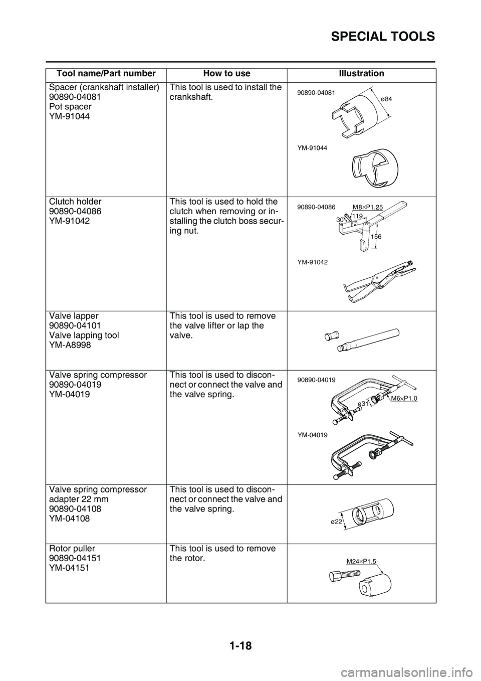
Spacer (crankshaft installer)
90890-04081
Pot spacer
YM-91044
This tool is used to install the
crankshaft.
Clutch holder
90890-04086
YM-91042
This tool is used to hold the
clutch when removing or in
-
stalling the clutch boss secur-
ing nut.
Valve lapper
90890-04101
Valve lapping tool
YM-A8998
This tool is used to remove
the valve lifter or lap the
valve.
Valve spring compressor
90890-04019
YM-04019
This tool is used to discon-
nect or connect the valve and
the valve spring.
Valve spring compressor
adapter 22 mm
90890-04108
YM-04108
This tool is used to discon-
nect or connect the valve and
the valve spring.
Rotor puller
90890-04151
YM-04151
This tool is used to remove
the rotor.
Tool name/Part number How to use Illustration
YM-91044
YM-04019
Page 41 of 360
CLEANING AND STORAGE
1-27
EAS1SL1049
CLEANING AND STORAGE
EAS1SL1050CLEANING
Frequent cleaning of your vehicle will enhance
its appearance, maintain performance, and ex
-
tend the life of parts.
1. Before cleaning, block the silencer outlet to
prevent water from entering. A plastic bag
secured with a rubber band may be used for
this purpose.
2. If the engine is contaminated with oil, apply
some degreaser to it with a brush. Do not
apply degreaser to the drive chain, the
sprockets, or the wheel axles.
3. Hose off dirt. Use only enough water pres-
sure to do the job.ECA
NOTICE
Do not use high-pressure washers or steam
cleaners. Otherwise, these may cause a fail
-
ure because of the entry of water.
4. After hosing off the dirt, wash all surfaces
with a mild detergent and warm water. Use
a toothbrush to clean hard-to-reach places.
5. Rinse the detergent with clean water, and
dry the surfaces with a soft towel or a cloth.
6. Immediately after cleaning, remove any wa-
ter from the drive chain with a paper towel,
and lubricate it to prevent rust.
7. Clean the seat with a vinyl upholstery clean-
er to keep the cover pliable and glossy.
8. Automotive wax may be applied to all paint-
ed or chromed surfaces. Avoid using such
wax as contains abrasives, because it may
scratch surfaces.
9. After completing the above, start the engine
and allow it to warm up for several minutes.
EAS1SL1051STORAGE
If your vehicle is to be stored for 60 days or
more, some preventive measures must be tak
-
en to avoid deterioration. After cleaning the ve-
hicle thoroughly, prepare it for storage as
follows:
1. Fill the fuel tank with gasoline.
2. Remove the spark plug, pour a spoonful of
engine oil (SAE 10W-40) into the spark plug
hole, and reinstall the plug. With the engine
stop switch pushed in, by pushing down the
kickstarter lever, crank the engine to coat
the cylinder walls with oil.
3. Remove the drive chain, clean it thoroughly
with solvent, and lubricate it Reinstall the
drive chain or store it in a plastic bag tied to
the frame.
4. Lubricate all cables.
5. Lift up the frame of the vehicle to keep the
wheels off the ground.
6. Tie a plastic bag over the muffler outlet to
prevent moisture from entering.
7. If the vehicle is to be stored in a place that is
humid or exposed to the sea breeze, apply a
light coat of oil to metal surfaces. Do not ap
-
ply oil to the seat or rubber parts.
TIP
Make any necessary repairs before the vehicle
is stored.
Page 59 of 360
TIGHTENING TORQUES
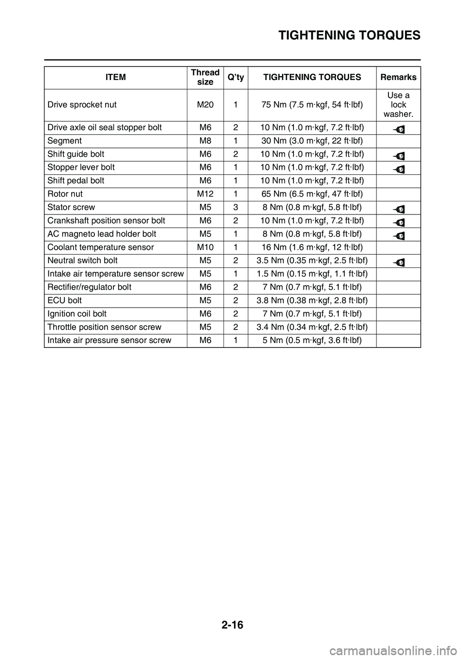
2-16
Drive sprocket nutM20175 Nm (7.5 m·kgf, 54 ft·lbf)
Use a
lock
washer.
Drive axle oil seal stopper boltM6210 Nm (1.0 m·kgf, 7.2 ft·lbf)
SegmentM8130 Nm (3.0 m·kgf, 22 ft·lbf)
Shift guide boltM6210 Nm (1.0 m·kgf, 7.2 ft·lbf)
Stopper lever boltM6110 Nm (1.0 m·kgf, 7.2 ft·lbf)
Shift pedal boltM6110 Nm (1.0 m·kgf, 7.2 ft·lbf)
Rotor nutM12165 Nm (6.5 m·kgf, 47 ft·lbf)
Stator screwM538 Nm (0.8 m·kgf, 5.8 ft·lbf)
Crankshaft position sensor boltM6210 Nm (1.0 m·kgf, 7.2 ft·lbf)
AC magneto lead holder boltM518 Nm (0.8 m·kgf, 5.8 ft·lbf)
Coolant temperature sensorM10116 Nm (1.6 m·kgf, 12 ft·lbf)
Neutral switch boltM523.5 Nm (0.35 m·kgf, 2.5 ft·lbf)
Intake air temperature sensor screwM511.5 Nm (0.15 m·kgf, 1.1 ft·lbf)
Rectifier/regulator boltM627 Nm (0.7 m·kgf, 5.1 ft·lbf)
ECU boltM523.8 Nm (0.38 m·kgf, 2.8 ft·lbf)
Ignition coil boltM627 Nm (0.7 m·kgf, 5.1 ft·lbf)
Throttle position sensor screwM523.4 Nm (0.34 m·kgf, 2.5 ft·lbf)
Intake air pressure sensor screwM615 Nm (0.5 m·kgf, 3.6 ft·lbf)
ITEMThread
sizeQ’ty TIGHTENING TORQUES Remarks
LT
LT
LT
LT
LT
LT
LT
Page 83 of 360
CABLE ROUTING DIAGRAM
2-40
1. Main harness
2. Radiator3. Throttle position sensor lead
4. Joint coupler
5. Intake air temperature sensor lead6. Intake air pressure sensor lead
7. Frame
8. Fuel hose9. High tension cord
10. Spark plug cap
11. Cylinder head cover12. Sub-wire harness
13. Injector coupler
14. Injector lead15. Throttle body
16. Air filter case
17. ECU18. Sub-wire harness coupler
A. Fix the main harness by the plastic clamp, and in-sert the projection of the plastic clamp into the
hole in the sheet metal of the radiator.
B. Insert the projection of the main harness into the
hole in the frame.
C. To the sub-wire harness
D. Pass the high tension cord above the fuel hose.
E. ±10°F. Install the spark plug cap with this facing the right
of the vehicle.
G. Push the spark plug cap home, where there shall
be no gap between it and the cylinder head cover.
H. Pass the injector lead to the top of the vehicle be-yond the fuel hose.I. Insert the coupler of the sub-wire harness into the
rib of the air filter case.
J. Pass the sub-wire harness between the ECU and
the air filter case.
Page 95 of 360
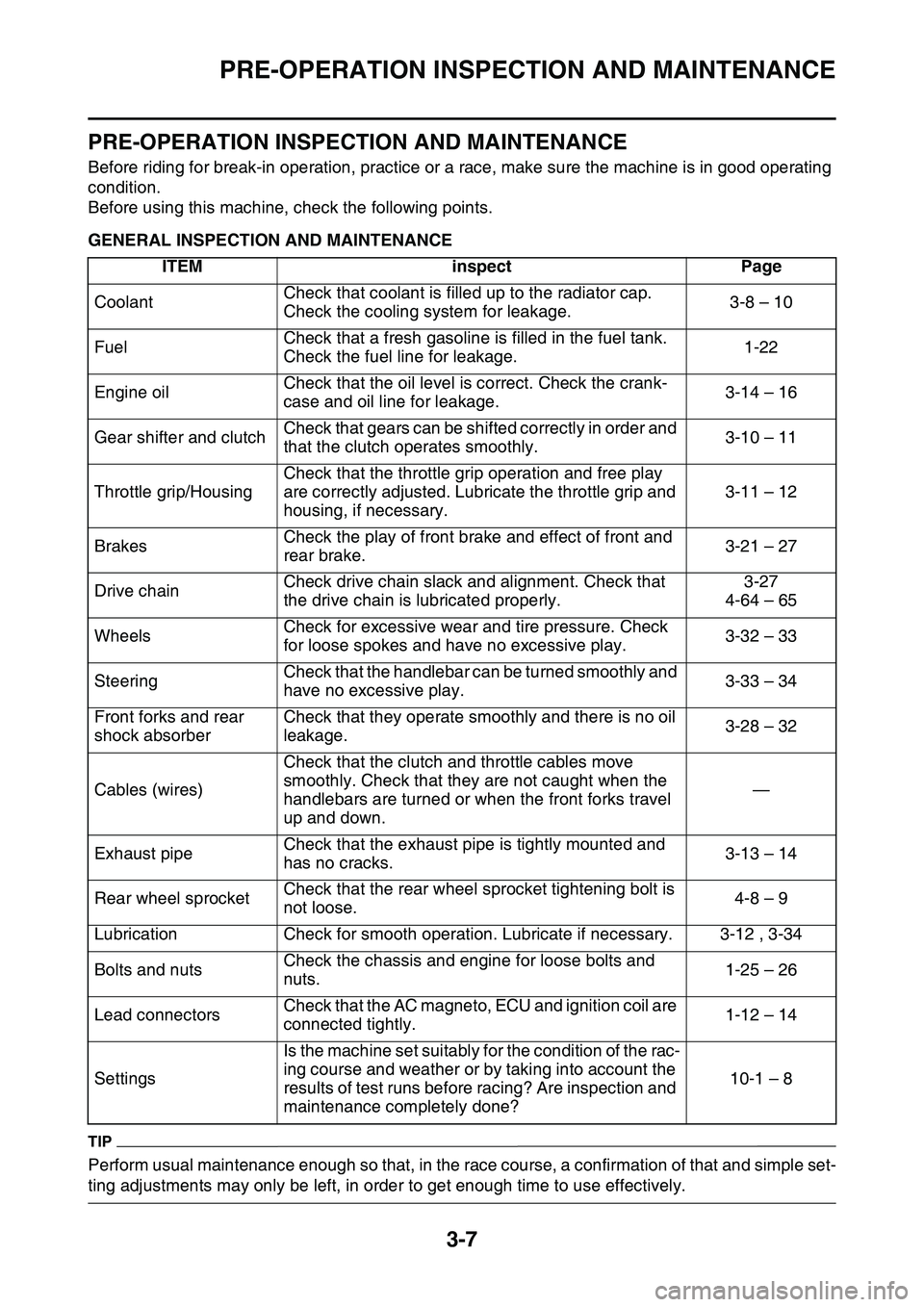
PRE-OPERATION INSPECTION AND MAINTENANCE
3-7
EAS1SL1067
PRE-OPERATION INSPECTION AND MAINTENANCE
Before riding for break-in operation, practice or a race, make sure the machine is in good operating
condition.
Before using this machine, check the following points.
EAS1SL1068GENERAL INSPECTION AND MAINTENANCE
TIP
Perform usual maintenance enough so that, in the race course, a confirmation of that and simple set-
ting adjustments may only be left, in order to get enough time to use effectively.
ITEMinspectPage
CoolantCheck that coolant is filled up to the radiator cap.
Check the cooling system for leakage.3-8 – 10
FuelCheck that a fresh gasoline is filled in the fuel tank.
Check the fuel line for leakage.1-22
Engine oilCheck that the oil level is correct. Check the crank-
case and oil line for leakage.3-14 – 16
Gear shifter and clutchCheck that gears can be shifted correctly in order and
that the clutch operates smoothly.3-10 – 11
Throttle grip/Housing
Check that the throttle grip operation and free play
are correctly adjusted. Lubricate the throttle grip and
housing, if necessary.
3-11 – 12
BrakesCheck the play of front brake and effect of front and
rear brake.3-21 – 27
Drive chainCheck drive chain slack and alignment. Check that
the drive chain is lubricated properly.3-27
4-64 – 65
WheelsCheck for excessive wear and tire pressure. Check
for loose spokes and have no excessive play.3-32 – 33
SteeringCheck that the handlebar can be turned smoothly and
have no excessive play.3-33 – 34
Front forks and rear
shock absorberCheck that they operate smoothly and there is no oil
leakage.3-28 – 32
Cables (wires)
Check that the clutch and throttle cables move
smoothly. Check that they are not caught when the
handlebars are turned or when the front forks travel
up and down.
—
Exhaust pipeCheck that the exhaust pipe is tightly mounted and
has no cracks.3-13 – 14
Rear wheel sprocketCheck that the rear wheel sprocket tightening bolt is
not loose.4-8 – 9
LubricationCheck for smooth operation. Lubricate if necessary. 3-12 , 3-34
Bolts and nutsCheck the chassis and engine for loose bolts and
nuts.1-25 – 26
Lead connectorsCheck that the AC magneto, ECU and ignition coil are
connected tightly.1-12 – 14
Settings
Is the machine set suitably for the condition of the rac-
ing course and weather or by taking into account the
results of test runs before racing? Are inspection and
maintenance completely done?10-1 – 8
Page 105 of 360
ENGINE
3-17
TIP
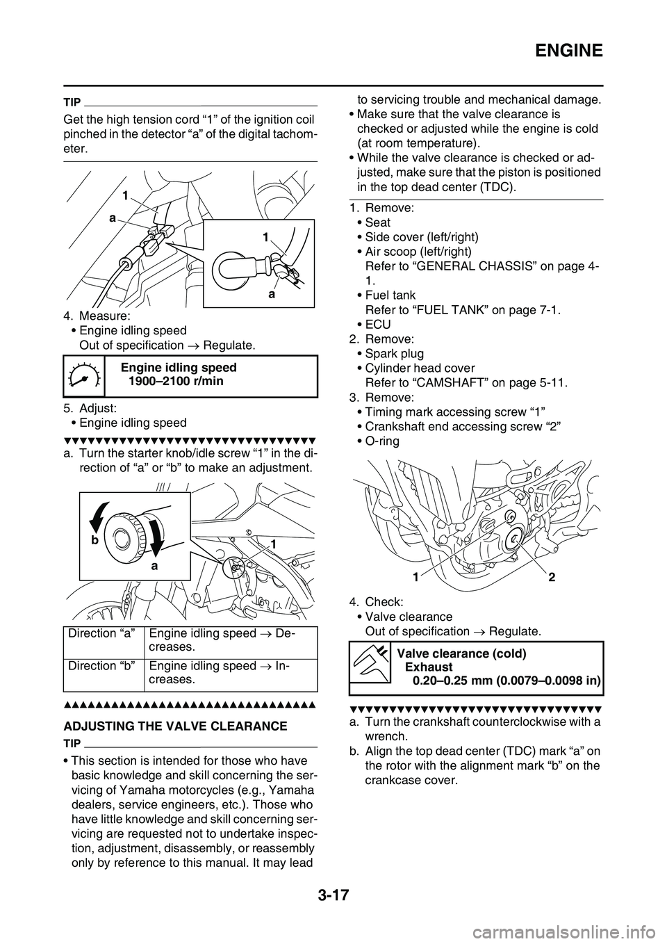
Get the high tension cord “1” of the ignition coil
pinched in the detector “a” of the digital tachom
-
eter.
4. Measure:
• Engine idling speed
Out of specification Regulate.
5. Adjust:
• Engine idling speed
▼▼▼▼▼▼▼▼▼▼▼▼▼▼▼▼▼▼▼▼▼▼▼▼▼▼▼▼▼▼▼▼
a. Turn the starter knob/idle screw “1” in the di-
rection of “a” or “b” to make an adjustment.
▲▲▲▲▲▲▲▲▲▲▲▲▲▲▲▲▲▲▲▲▲▲▲▲▲▲▲▲▲▲▲▲
EAS1SL1088ADJUSTING THE VALVE CLEARANCE
TIP
• This section is intended for those who have
basic knowledge and skill concerning the ser
-
vicing of Yamaha motorcycles (e.g., Yamaha
dealers, service engineers, etc.). Those who
have little knowledge and skill concerning ser
-
vicing are requested not to undertake inspec-
tion, adjustment, disassembly, or reassembly
only by reference to this manual. It may lead to servicing trouble and mechanical damage.
• Make sure that the valve clearance is
checked or adjusted while the engine is cold
(at room temperature).
• While the valve clearance is checked or ad-
justed, make sure that the piston is positioned
in the top dead center (TDC).
1. Remove:
• Seat
• Side cover (left/right)
• Air scoop (left/right)
Refer to “GENERAL CHASSIS” on page 4-
1.
• Fuel tank
Refer to “FUEL TANK” on page 7-1.
•ECU
2. Remove:
• Spark plug
• Cylinder head cover
Refer to “CAMSHAFT” on page 5-11.
3. Remove:
• Timing mark accessing screw “1”
• Crankshaft end accessing screw “2”
• O-ring
4. Check:
• Valve clearance
Out of specification Regulate.
▼▼▼▼▼▼▼▼▼▼▼▼▼▼▼▼▼▼▼▼▼▼▼▼▼▼▼▼▼▼▼▼
a. Turn the crankshaft counterclockwise with a
wrench.
b. Align the top dead center (TDC) mark “a” on
the rotor with the alignment mark “b” on the
crankcase cover.
Engine idling speed
1900–2100 r/min
Direction “a”Engine idling speed De-
creases.
Direction “b”Engine idling speed In-
creases.
1 1
a a
1 b
a
Valve clearance (cold)
Exhaust
0.20–0.25 mm (0.0079–0.0098 in)
1
2