oil YAMAHA YZ450F 2016 Owners Manual
[x] Cancel search | Manufacturer: YAMAHA, Model Year: 2016, Model line: YZ450F, Model: YAMAHA YZ450F 2016Pages: 362, PDF Size: 10.49 MB
Page 342 of 362
TROUBLESHOOTING
9-1
EASB111348
TROUBLESHOOTING
EASB111349GENERAL INFORMATION
TIP
The following guide for troubleshooting does
not cover all the possible causes of trouble. It
should be helpful, however, as a guide to basic
troubleshooting. Refer to the relative procedure
in this manual for checks, adjustments, and re-
placement of parts.
EASB111350STARTING FAILURES
Engine
1. Cylinder and cylinder head
• Loose spark plug
• Loose cylinder head or cylinder
• Damaged cylinder head gasket
• Damaged cylinder gasket
• Worn or damaged cylinder
• Incorrect valve clearance
• Improperly sealed valve
• Incorrect valve-to-valve-seat contact
• Incorrect valve timing
• Faulty valve spring
• Seized valve
2. Piston and piston ring(s)
• Improperly installed piston ring
• Damaged, worn or fatigued piston ring
• Seized piston ring
• Seized or damaged piston
3. Air filter
• Improperly installed air filter
• Clogged air filter element
4. Crankcase and crankshaft
• Improperly assembled crankcase
• Seized crankshaft
Fuel system
1. Fuel tank
• Empty fuel tank
• Clogged fuel tank breather hose
• Deteriorated or contaminated fuel
• Clogged or damaged fuel hose
2. Fuel pump
• Faulty fuel pump
3. Throttle body
• Deteriorated or contaminated fuel
• Sucked-in airElectrical system
1. Spark plug
• Incorrect spark plug gap
• Incorrect spark plug heat range
• Fouled spark plug
• Worn or damaged electrode
• Worn or damaged insulator
2. Ignition coil
• Cracked or broken ignition coil body
• Broken or shorted primary or secondary
coils
3. Ignition system
• Faulty ECU
• Faulty crankshaft position sensor
• Broken generator rotor woodruff key
4. Switches and wiring
• Faulty ECU
• Faulty engine stop switch
• Broken or shorted wiring
• Faulty neutral switch
• Improperly grounded circuit
• Loose connections
EASB111351INCORRECT ENGINE IDLING SPEED
Engine
1. Cylinder and cylinder head
• Incorrect valve clearance
• Damaged valve train components
2. Air filter
• Clogged air filter element
Fuel system
1. Throttle body
• Damaged or loose throttle body joint
• Improperly synchronized throttle bodies
• Improper throttle cable free play
• Flooded throttle body
Electrical system
1. Spark plug
• Incorrect spark plug gap
• Incorrect spark plug heat range
• Fouled spark plug
• Worn or damaged electrode
• Worn or damaged insulator
• Faulty spark plug cap
2. Ignition coil
• Broken or shorted primary or secondary
coils
• Cracked or broken ignition coil
Page 343 of 362
TROUBLESHOOTING
9-2
3. Ignition system
• Faulty ECU
• Faulty crankshaft position sensor
• Broken generator rotor woodruff key
EASB111352POOR MEDIUM-AND-HIGH-SPEED PER-
FORMANCE
Refer to “STARTING FAILURES” on page 9-1.
Engine
1. Air filter
• Clogged air filter element
Fuel system
1. Fuel pump
• Faulty fuel pump
2. Throttle body
• Defective throttle body
3. ECU
• Faulty ECU
EASB111353SHIFTING IS DIFFICULT
Refer to “CLUTCH” on page 5-38.
EASB111354SHIFT PEDAL DOES NOT MOVE
Engine
1. Shift shaft
• Bent shift shaft
2. Shift drum and shift forks
• Foreign object in a shift drum groove
• Seized shift fork
• Bent shift fork guide bar
3. Transmission
• Seized transmission gear
• Foreign object between transmission gears
• Improperly assembled transmission
EASB111355JUMPS OUT OF GEAR
Engine
1. Shift shaft
• Incorrect shift pedal position
• Improperly returned stopper lever
2. Shift forks
• Worn shift fork
3. Shift drum
• Incorrect axial play
• Worn shift drum groove
4. Transmission
• Worn gear dog
EASB111356
CLUTCH SLIPS
Engine
1. Clutch
• Improperly assembled clutch
• Loose or fatigued clutch spring
• Worn friction plate
• Worn clutch plate
2. Engine oil
• Incorrect oil level
• Incorrect oil viscosity (low)
• Deteriorated oil
EASB111357CLUTCH DRAGS
Engine
1. Clutch
• Unevenly tensioned clutch springs
• Warped pressure plate
• Bent clutch plate
• Swollen friction plate
• Bent clutch push rod
• Damaged clutch boss
• Burnt primary driven gear bushing
2. Engine oil
• Incorrect oil level
• Incorrect oil viscosity (high)
• Deteriorated oil
EASB111358OVERHEATING
Engine
1. Cylinder head and piston
• Heavy carbon buildup
• Clogged coolant passages
2. Engine oil
• Incorrect oil level
• Incorrect oil viscosity
• Inferior oil quality
Cooling system
1. Coolant
• Low coolant level
2. Radiator
• Damaged or leaking radiator
• Faulty radiator cap
• Bent or damaged radiator fin
3. Water pump
• Damaged or faulty water pump
• Damaged hose
• Improperly connected hose
• Damaged pipe
• Improperly connected pipe
Page 344 of 362
TROUBLESHOOTING
9-3
Fuel system
1. Throttle body
• Damaged or loose throttle body joint
2. Air filter
• Clogged air filter element
Chassis
1. Brake(s)
• Dragging brake
Electrical system
1. Spark plug
• Incorrect spark plug gap
• Incorrect spark plug heat range
2. Ignition system
• Faulty ECU
• Faulty coolant temperature sensor
EASB111359OVERCOOLING
Cooling system
1. Coolant temperature sensor
• Faulty coolant temperature sensor
EASB111360POOR BRAKING PERFORMANCE
Chassis
1. Brake(s)
• Worn brake pad
• Worn brake disc
• Air in hydraulic brake system
• Leaking brake fluid
• Defective master cylinder kit
• Faulty brake caliper kit
• Faulty brake caliper seal
• Loose union bolt
• Damaged brake hose
• Oil or grease on the brake disc
• Oil or grease on the brake pad
• Incorrect brake fluid level
EASB111361FRONT FORK OIL LEAKING
Chassis
1. Front fork
• Bent, damaged, or rusty inner tube
• Cracked or damaged outer tube
• Improperly installed oil seal
• Damaged oil seal lip
• Incorrect oil level (high)
• Loose damper rod assembly bolt
• Damaged damper rod assembly bolt copper
washer
• Cracked or damaged cap bolt O-ring
EASB111362FAULTY FRONT FORK LEGS
Chassis
1. Front fork
• Bent or damaged inner tube
• Bent or damaged outer tube
• Broken fork spring
• Bent or damaged damper rod
• Incorrect oil viscosity
• Incorrect oil level
EASB111363UNSTABLE HANDLING
Chassis
1. Handlebar
• Bent or improperly installed handlebar
2. Steering head components
• Improperly installed upper bracket
• Improperly installed lower bracket
(improperly tightened ring nut)
• Bent steering stem
• Damaged ball bearing or bearing race
3. Front fork leg (s)
• Uneven oil levels (both front fork legs)
• Unevenly tensioned fork spring (both front
fork legs)
• Broken fork spring
• Bent or damaged inner tube
• Bent or damaged outer tube
4. Swingarm
• Worn bearing or bushing
• Bent or damaged swingarm
5. Rear shock absorber assembly (-ies)
• Faulty rear shock absorber spring
• Leaking oil or gas
6. Tire (s)
• Uneven tire pressures (front and rear)
• Incorrect tire pressure
• Uneven tire wear
7. Wheel (s)
• Incorrect wheel balance
• Broken or loose spoke
• Damaged wheel bearing
• Bent or loose wheel axle
• Excessive wheel runout
8. Frame
• Bent frame
• Damaged steering head pipe
• Improperly installed bearing race
Page 345 of 362

LIST OF SELF-DIAGNOSTIC AND FAIL-SAFE ACTIONS
9-4
EASB111364
LIST OF SELF-DIAGNOSTIC AND FAIL-SAFE ACTIONS
LIST OF DIAGNOSTIC CODES
COMMUNICATION ERROR WITH YAMAHA DIAGNOSTIC TOOLFault
codeITEM Page
12 Crankshaft position sensor: no normal signals are received from the
crankshaft position sensor.8-14
13 Intake air pressure sensor: open or short circuit detected. 8-15
14 Intake air pressure sensor: hose system malfunction (clogged or de-
tached hose)8-16
15 Throttle position sensor: open or short circuit detected. 8-17
16 Throttle position sensor: stuck throttle position sensor is detected. 8-19
21 Coolant temperature sensor: open or short circuit detected. 8-20
22 Intake air temperature sensor: open or short circuit detected. 8-21
30 The vehicle has overturned. 8-22
33 Ignition coil: open or short circuit detected in the primary lead of the
ignition coil.8-23
39 Injector: open or short circuit detected. 8-24
41 ECU: built-in lean angle sensor malfunction 8-25
44 EEPROM fault code No.: an error is detected while reading or writing
on EEPROM.8-26
46 Vehicle system power supply: normal voltage is not supplied to the
ECU.8-27
50 ECU: faulty ECU memory 8-28
Fault
codeITEM Page
Waiting
for con-
nectionNo communication signal is received from the ECU.
8-28
Er-2 Signals from the ECU cannot be received within the specified period
of time.8-29
Er-3 Data from the ECU cannot be received correctly. 8-30
Er-4 Registered data cannot be received from the Yamaha diagnostic tool. 8-31
Page 347 of 362
LIST OF SELF-DIAGNOSTIC AND FAIL-SAFE ACTIONS
9-6
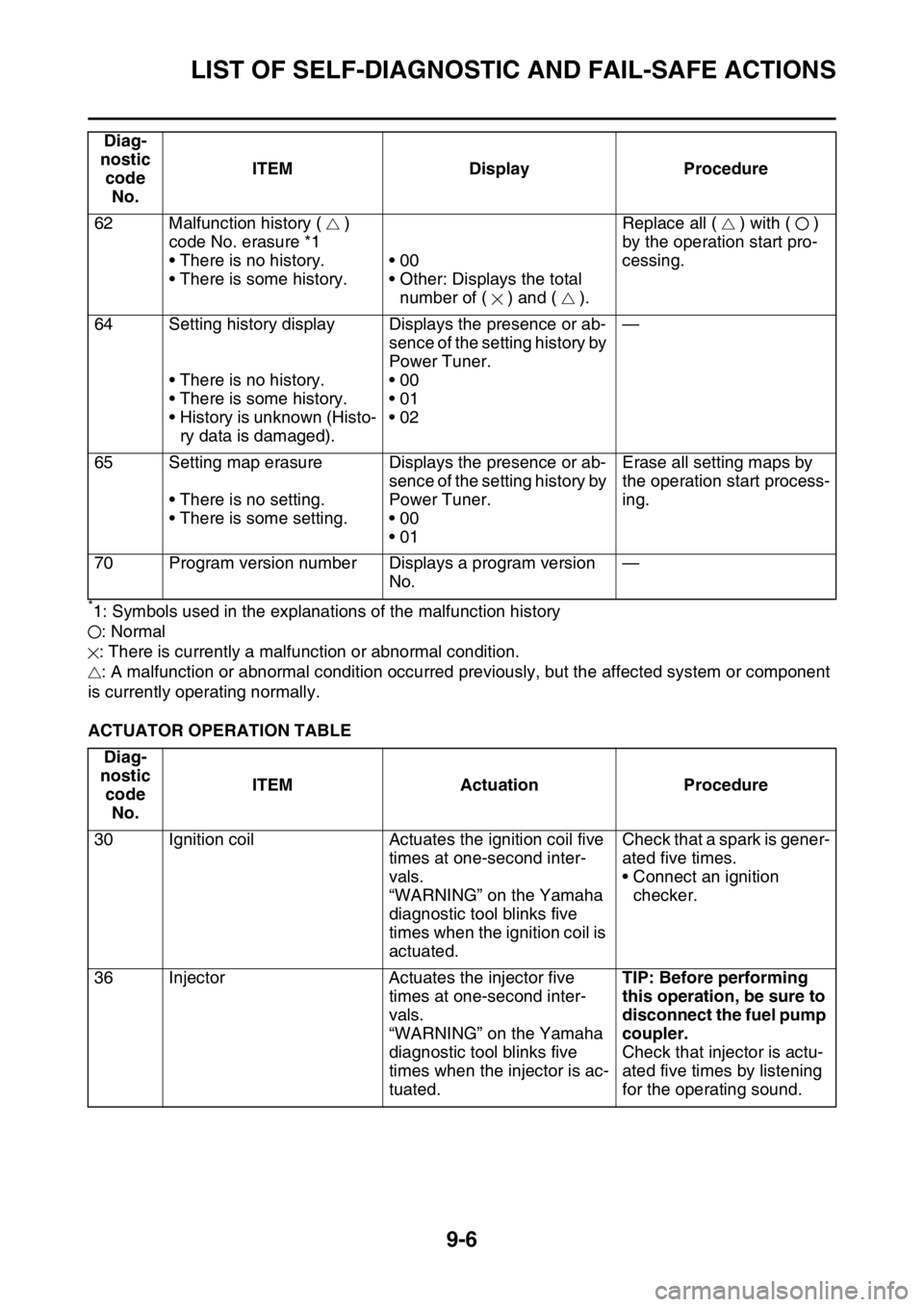
*1: Symbols used in the explanations of the malfunction history
: Normal
: There is currently a malfunction or abnormal condition.
: A malfunction or abnormal condition occurred previously, but the affected system or component
is currently operating normally.
ACTUATOR OPERATION TABLE62 Malfunction history ( )
code No. erasure *1
• There is no history.
• There is some history.•00
• Other: Displays the total
number of ( ) and ( ).Replace all ( ) with ( )
by the operation start pro-
cessing.
64 Setting history display
• There is no history.
• There is some history.
• History is unknown (Histo-
ry data is damaged).Displays the presence or ab-
sence of the setting history by
Power Tuner.
•00
•01
•02—
65 Setting map erasure
• There is no setting.
• There is some setting.Displays the presence or ab-
sence of the setting history by
Power Tuner.
•00
•01Erase all setting maps by
the operation start process-
ing.
70 Program version number Displays a program version
No.—
Diag-
nostic
code
No.ITEM Actuation Procedure
30 Ignition coil Actuates the ignition coil five
times at one-second inter-
vals.
“WARNING” on the Yamaha
diagnostic tool blinks five
times when the ignition coil is
actuated.Check that a spark is gener-
ated five times.
• Connect an ignition
checker.
36 Injector Actuates the injector five
times at one-second inter-
vals.
“WARNING” on the Yamaha
diagnostic tool blinks five
times when the injector is ac-
tuated.TIP: Before performing
this operation, be sure to
disconnect the fuel pump
coupler.
Check that injector is actu-
ated five times by listening
for the operating sound. Diag-
nostic
code
No.ITEM Display Procedure
Page 349 of 362
10
TUNING
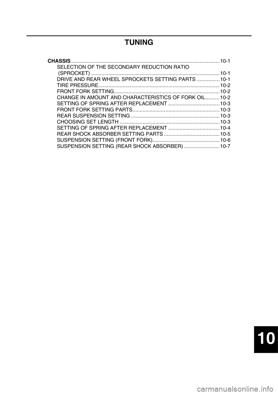
CHASSIS........................................................................................................ 10-1
SELECTION OF THE SECONDARY REDUCTION RATIO
(SPROCKET) .......................................................................................... 10-1
DRIVE AND REAR WHEEL SPROCKETS SETTING PARTS ................ 10-1
TIRE PRESSURE..................................................................................... 10-2
FRONT FORK SETTING.......................................................................... 10-2
CHANGE IN AMOUNT AND CHARACTERISTICS OF FORK OIL.......... 10-2
SETTING OF SPRING AFTER REPLACEMENT .................................... 10-3
FRONT FORK SETTING PARTS............................................................. 10-3
REAR SUSPENSION SETTING .............................................................. 10-3
CHOOSING SET LENGTH ...................................................................... 10-3
SETTING OF SPRING AFTER REPLACEMENT .................................... 10-4
REAR SHOCK ABSORBER SETTING PARTS ....................................... 10-5
SUSPENSION SETTING (FRONT FORK)............................................... 10-6
SUSPENSION SETTING (REAR SHOCK ABSORBER) ......................... 10-7
Page 351 of 362
CHASSIS
10-2
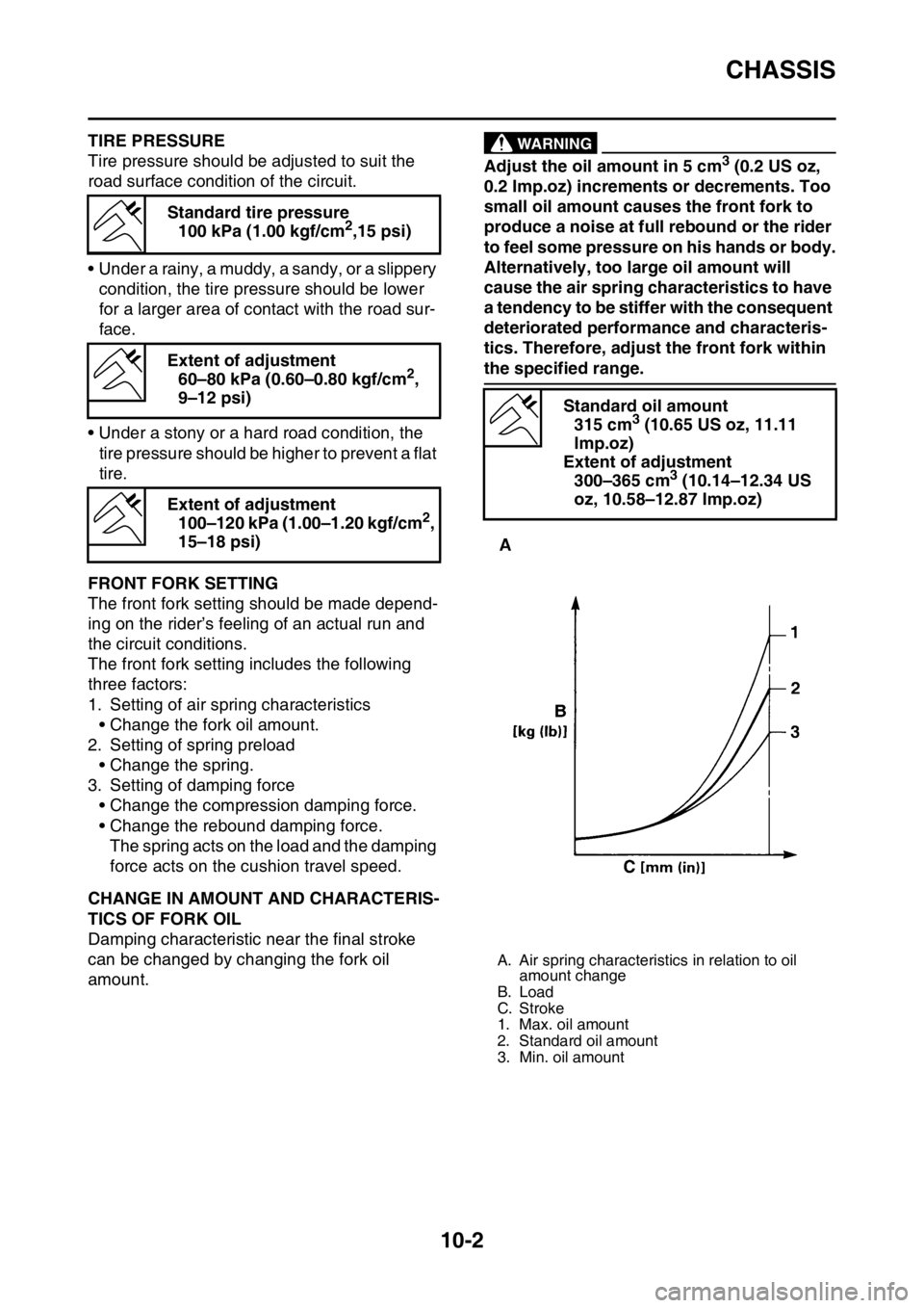
EASB111369TIRE PRESSURE
Tire pressure should be adjusted to suit the
road surface condition of the circuit.
• Under a rainy, a muddy, a sandy, or a slippery
condition, the tire pressure should be lower
for a larger area of contact with the road sur-
face.
• Under a stony or a hard road condition, the
tire pressure should be higher to prevent a flat
tire.
EASB111370FRONT FORK SETTING
The front fork setting should be made depend-
ing on the rider’s feeling of an actual run and
the circuit conditions.
The front fork setting includes the following
three factors:
1. Setting of air spring characteristics
• Change the fork oil amount.
2. Setting of spring preload
• Change the spring.
3. Setting of damping force
• Change the compression damping force.
• Change the rebound damping force.
The spring acts on the load and the damping
force acts on the cushion travel speed.
EASB111371CHANGE IN AMOUNT AND CHARACTERIS-
TICS OF FORK OIL
Damping characteristic near the final stroke
can be changed by changing the fork oil
amount.
EWA1DX4001
WARNING
Adjust the oil amount in 5 cm3 (0.2 US oz,
0.2 Imp.oz) increments or decrements. Too
small oil amount causes the front fork to
produce a noise at full rebound or the rider
to feel some pressure on his hands or body.
Alternatively, too large oil amount will
cause the air spring characteristics to have
a tendency to be stiffer with the consequent
deteriorated performance and characteris-
tics. Therefore, adjust the front fork within
the specified range. Standard tire pressure
100 kPa (1.00 kgf/cm
2,15 psi)
Extent of adjustment
60–80 kPa (0.60–0.80 kgf/cm
2,
9–12 psi)
Extent of adjustment
100–120 kPa (1.00–1.20 kgf/cm
2,
15–18 psi)
Standard oil amount
315 cm3 (10.65 US oz, 11.11
lmp.oz)
Extent of adjustment
300–365 cm
3 (10.14–12.34 US
oz, 10.58–12.87 Imp.oz)
A. Air spring characteristics in relation to oil
amount change
B. Load
C. Stroke
1. Max. oil amount
2. Standard oil amount
3. Min. oil amount
Page 355 of 362
CHASSIS
10-6
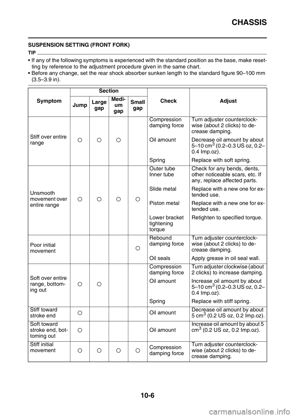
EASB111378SUSPENSION SETTING (FRONT FORK)
TIP
• If any of the following symptoms is experienced with the standard position as the base, make reset-
ting by reference to the adjustment procedure given in the same chart.
• Before any change, set the rear shock absorber sunken length to the standard figure 90–100 mm
(3.5–3.9 in).
SymptomSection
Check Adjust
JumpLarge
gapMedi-
um
gapSmall
gap
Stiff over entire
rangeCompression
damping forceTurn adjuster counterclock-
wise (about 2 clicks) to de-
crease damping.
Oil amount Decrease oil amount by about
5–10 cm
3 (0.2–0.3 US oz, 0.2–
0.4 Imp.oz).
Spring Replace with soft spring.
Unsmooth
movement over
entire rangeOuter tube
Inner tubeCheck for any bends, dents,
other noticeable scars, etc. If
any, replace affected parts.
Slide metal Replace with a new one for ex-
tended use.
Piston metal Replace with a new one for ex-
tended use.
Lower bracket
tightening
torqueRetighten to specified torque.
Poor initial
movementRebound
damping forceTurn adjuster counterclock-
wise (about 2 clicks) to de-
crease damping.
Oil seals Apply grease in oil seal wall.
Soft over entire
range, bottom-
ing outCompression
damping forceTurn adjuster clockwise (about
2 clicks) to increase damping.
Oil amount Increase oil amount by about
5–10 cm
3 (0.2–0.3 US oz, 0.2–
0.4 Imp.oz).
Spring Replace with stiff spring.
Stiff toward
stroke endOil amountDecrease oil amount by about
5 cm
3 (0.2 US oz, 0.2 Imp.oz).
Soft toward
stroke end, bot-
toming outOil amountIncrease oil amount by about 5
cm
3 (0.2 US oz, 0.2 Imp.oz).
Stiff initial
movementCompression
damping forceTurn adjuster counterclock-
wise (about 2 clicks) to de-
crease damping.
Page 356 of 362

CHASSIS
10-7
EASB111379SUSPENSION SETTING (REAR SHOCK ABSORBER)
TIP
• If any of the following symptoms is experienced with the standard position as the base, make reset-
ting by reference to the adjustment procedure given in the same chart.
• Adjust the rebound damping in 2-click increments or decrements.
• Adjust the low compression damping in 1-click increments or decrements.
• Adjust the high compression damping in 1/6 turn increments or decrements. Low front, tend-
ing to lower
front postureCompression
damping forceTurn adjuster clockwise (about
2 clicks) to increase damping.
Rebound
damping forceTurn adjuster counterclock-
wise (about 2 clicks) to de-
crease damping.
Balance with
rear endSet sunken length for 95–100
mm (3.7–3.9 in) when one
passenger is astride seat (low-
er rear posture).
Oil amount Increase oil amount by about 5
cm
3 (0.2 US oz, 0.2 Imp.oz).
“Obtrusive”
front, tending to
upper front pos-
tureCompression
damping forceTurn adjuster counterclock-
wise (about 2 clicks) to de-
crease damping.
Balance with
rear endSet sunken length for 90–95
mm (3.5–3.7 in) when one
passenger is astride seat (up-
per rear posture).
Spring Replace with soft spring.
Oil amount Decrease oil amount by about
5–10 cm
3 (0.2–0.3 US oz, 0.2–
0.4 Imp.oz).
SymptomSection
Check Adjust
JumpLarge
gapMedi-
um
gapSmall
gap
Stiff, tending to
sinkRebound
damping forceTurn adjuster counterclock-
wise (about 2 clicks) to de-
crease damping.
Spring set
lengthSet sunken length for 90–100
mm (3.5–3.9 in) when one
passenger is astride seat.
Spongy and un-
stableRebound
damping forceTurn adjuster clockwise (about
2 clicks) to increase damping.
Low compres-
sion dampingTurn adjuster clockwise (about
1 click) to increase damping.
Spring Replace with stiff spring. SymptomSection
Check Adjust
JumpLarge
gapMedi-
um
gapSmall
gap
Page 358 of 362

EASB111381
WIRING DIAGRAM
YZ450F/YZ450FG 2016
1. Crankshaft position sensor
2. AC magneto
3. Rectifier/regulator
4. Joint connector
5. Condenser
6. Coupler for connecting option-
al part
7. Engine stop switch
8. Neutral switch
9. Launch control switch
10. ECU
11. Ignition coil
12. Spark plug
13. Fuel injector
14. Fuel pump
15. Intake air temperature sensor
16. Coolant temperature sensor
17. Throttle position sensor
18. Intake air pressure sensor
19. Ignition coil sub-lead
EASB111382COLOR CODE
BBlack
Gy Gray
LBlue
Lg Light green
O Orange
PPink
RRed
Sb Sky blue
Y Yellow
B/L Black/Blue
B/R Black/Red
B/W Black/White
B/Y Black/Yellow
Br/W Brown/White
G/W Green/White
L/W Blue/White
P/B Pink/Black
R/B Red/Black
Y/G Yellow/Green
Y/R Yellow/Red
Y/W Yellow/White