YAMAHA YZ450F 2016 Owners Manual
Manufacturer: YAMAHA, Model Year: 2016, Model line: YZ450F, Model: YAMAHA YZ450F 2016Pages: 362, PDF Size: 10.49 MB
Page 131 of 362
REAR WHEEL
4-7
EASB111127
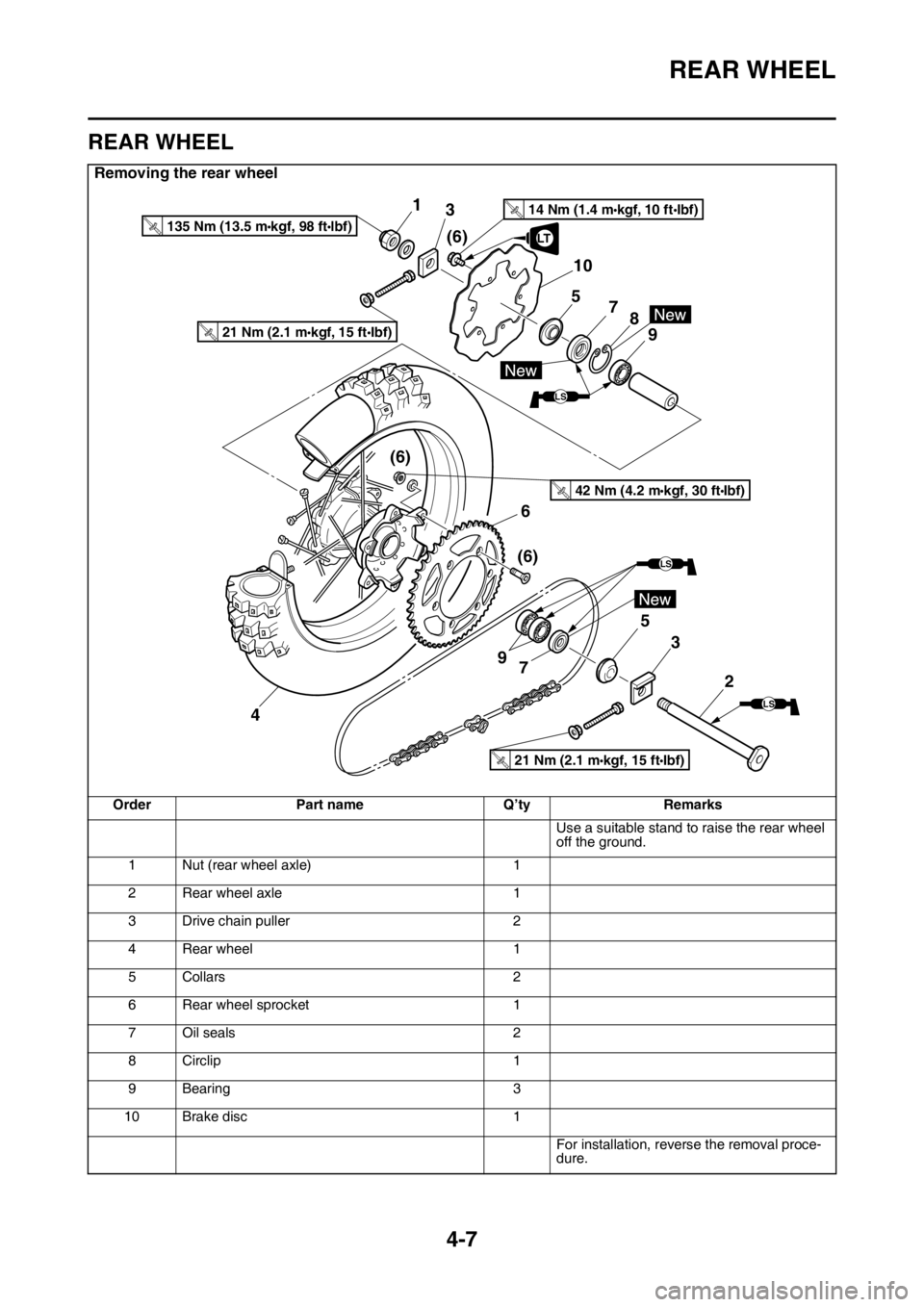
REAR WHEEL
Removing the rear wheel
Order Part name Q’ty Remarks
Use a suitable stand to raise the rear wheel
off the ground.
1 Nut (rear wheel axle) 1
2 Rear wheel axle 1
3 Drive chain puller 2
4 Rear wheel 1
5Collars 2
6 Rear wheel sprocket 1
7Oil seals 2
8 Circlip 1
9 Bearing 3
10 Brake disc 1
For installation, reverse the removal proce-
dure.
(6)
21 Nm (2.1 m•kgf, 15 ft•Ibf)T.R.
2 5
7 9
LS
LS(6)
46
1
(6) 3
LS
8
9 10
7 5
LT
14 Nm (1.4 m•kgf, 10 ft•Ibf)T.R.
3
21 Nm (2.1 m•kgf, 15 ft•Ibf)T.R.
42 Nm (4.2 m•kgf, 30 ft•Ibf)T.R.
135 Nm (13.5 m•kgf, 98 ft•lbf)T.R.
Page 132 of 362
REAR WHEEL
4-8
EASB111128REMOVING THE REAR WHEEL
1. Use a suitable stand to raise the rear wheel
off the ground.
EWA
WARNING
Securely support the vehicle so that there is
no danger of it falling over.
2. Remove:
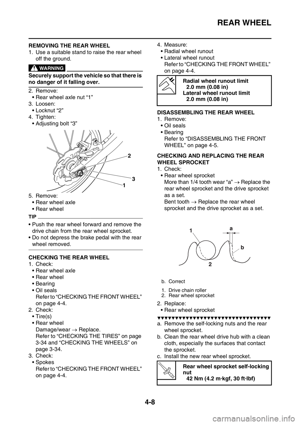
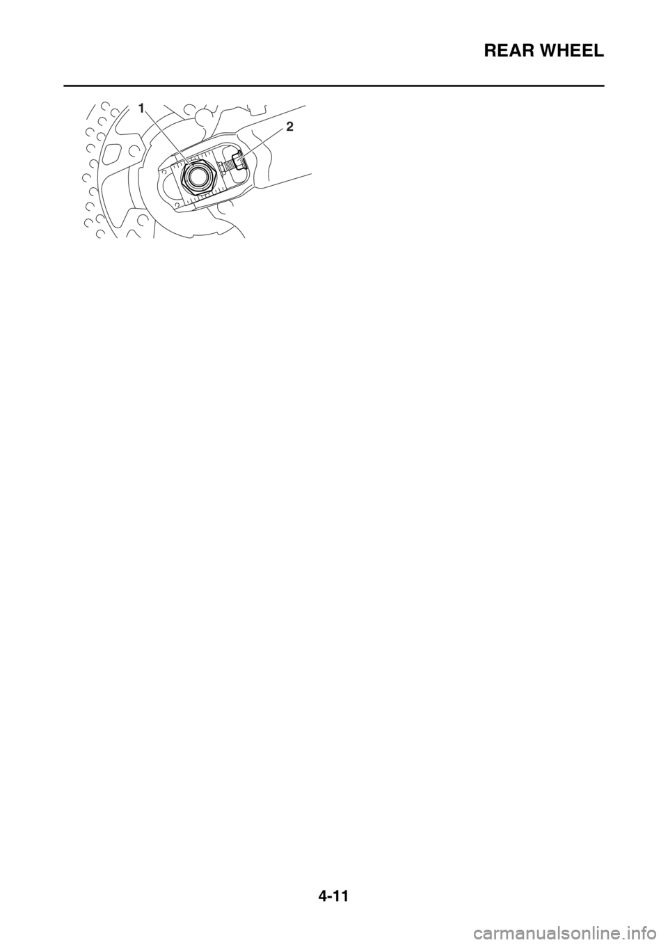
• Rear wheel axle nut “1”
3. Loosen:
• Locknut “2”
4. Tighten:
• Adjusting bolt “3”
5. Remove:
• Rear wheel axle
• Rear wheel
TIP
• Push the rear wheel forward and remove the
drive chain from the rear wheel sprocket.
• Do not depress the brake pedal with the rear
wheel removed.
EASB111129CHECKING THE REAR WHEEL
1. Check:
• Rear wheel axle
• Rear wheel
• Bearing
• Oil seals
Refer to “CHECKING THE FRONT WHEEL”
on page 4-4.
2. Check:
•Tire(s)
• Rear wheel
Damage/wear Replace.
Refer to “CHECKING THE TIRES” on page
3-34 and “CHECKING THE WHEELS” on
page 3-34.
3. Check:
• Spokes
Refer to “CHECKING THE FRONT WHEEL”
on page 4-4.4. Measure:
• Radial wheel runout
• Lateral wheel runout
Refer to “CHECKING THE FRONT WHEEL”
on page 4-4.
EASB111130DISASSEMBLING THE REAR WHEEL
1. Remove:
• Oil seals
• Bearing
Refer to “DISASSEMBLING THE FRONT
WHEEL” on page 4-5.
EASB111131CHECKING AND REPLACING THE REAR
WHEEL SPROCKET
1. Check:
• Rear wheel sprocket
More than 1/4 tooth wear “a” Replace the
rear wheel sprocket and the drive sprocket
as a set.
Bent tooth Replace the rear wheel
sprocket and the drive sprocket as a set.
2. Replace:
• Rear wheel sprocket
▼▼▼▼▼▼▼▼▼▼▼▼▼▼▼▼▼▼▼▼▼▼▼▼▼▼▼▼▼▼▼▼
a. Remove the self-locking nuts and the rear
wheel sprocket.
b. Clean the rear wheel drive hub with a clean
cloth, especially the surfaces that contact
the sprocket.
c. Install the new rear wheel sprocket.
3
12
Radial wheel runout limit
2.0 mm (0.08 in)
Lateral wheel runout limit
2.0 mm (0.08 in)
b. Correct
1. Drive chain roller
2. Rear wheel sprocket
Rear wheel sprocket self-locking
nut
42 Nm (4.2 m·kgf, 30 ft·lbf)
T R..
Page 133 of 362
REAR WHEEL
4-9
TIP
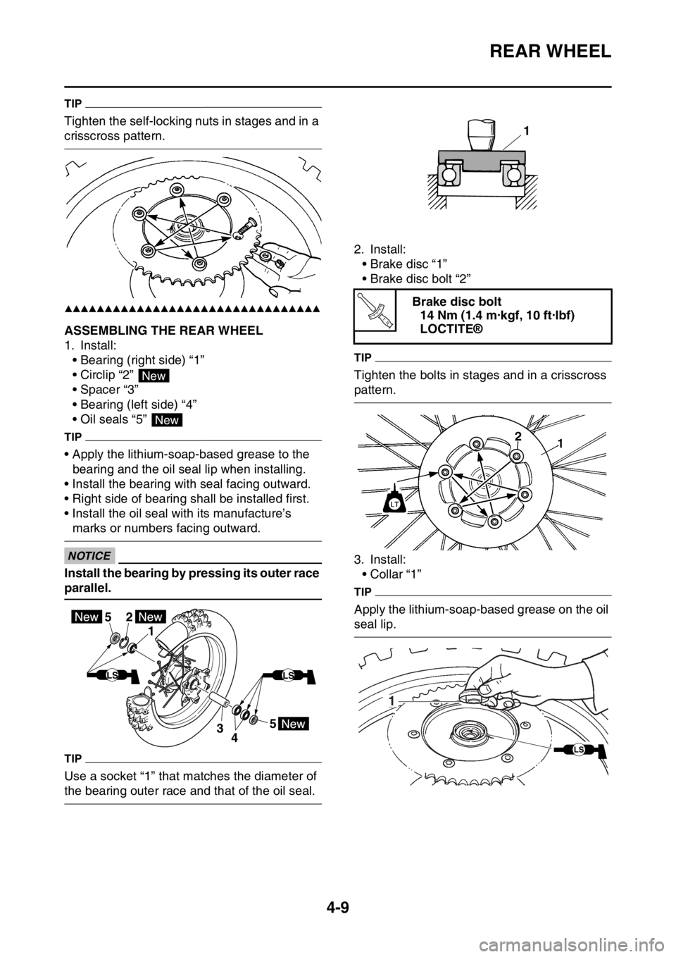
Tighten the self-locking nuts in stages and in a
crisscross pattern.
▲▲▲▲▲▲▲▲▲▲▲▲▲▲▲▲▲▲▲▲▲▲▲▲▲▲▲▲▲▲▲▲
EASB111132ASSEMBLING THE REAR WHEEL
1. Install:
• Bearing (right side) “1”
• Circlip “2”
• Spacer “3”
• Bearing (left side) “4”
• Oil seals “5”
TIP
• Apply the lithium-soap-based grease to the
bearing and the oil seal lip when installing.
• Install the bearing with seal facing outward.
• Right side of bearing shall be installed first.
• Install the oil seal with its manufacture’s
marks or numbers facing outward.
ECA
NOTICE
Install the bearing by pressing its outer race
parallel.
TIP
Use a socket “1” that matches the diameter of
the bearing outer race and that of the oil seal.2. Install:
• Brake disc “1”
• Brake disc bolt “2”
TIP
Tighten the bolts in stages and in a crisscross
pattern.
3. Install:
• Collar “1”
TIP
Apply the lithium-soap-based grease on the oil
seal lip.
New
New
5
43 1
25
LSLS
Brake disc bolt
14 Nm (1.4 m·kgf, 10 ft·lbf)
LOCTITE®
1
T R..
1
LS
Page 134 of 362
REAR WHEEL
4-10
EASB111133INSTALLING THE REAR WHEEL
1. Install:
• Rear wheel
TIP
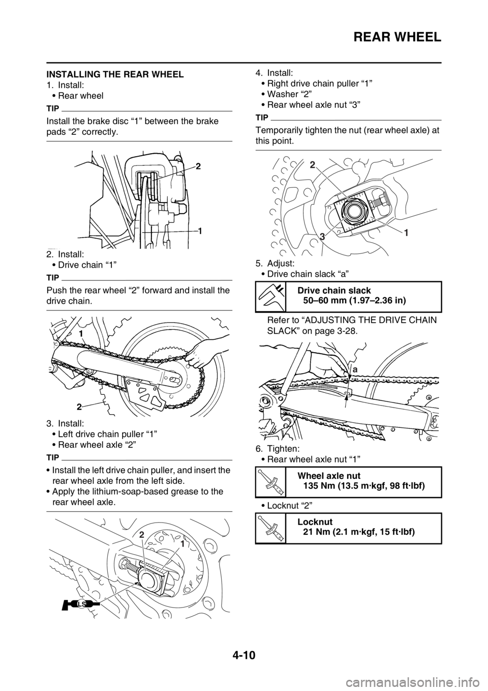
Install the brake disc “1” between the brake
pads “2” correctly.
2. Install:
• Drive chain “1”
TIP
Push the rear wheel “2” forward and install the
drive chain.
3. Install:
• Left drive chain puller “1”
• Rear wheel axle “2”
TIP
• Install the left drive chain puller, and insert the
rear wheel axle from the left side.
• Apply the lithium-soap-based grease to the
rear wheel axle.4. Install:
• Right drive chain puller “1”
• Washer “2”
• Rear wheel axle nut “3”
TIP
Temporarily tighten the nut (rear wheel axle) at
this point.
5. Adjust:
• Drive chain slack “a”
Refer to “ADJUSTING THE DRIVE CHAIN
SLACK” on page 3-28.
6. Tighten:
• Rear wheel axle nut “1”
• Locknut “2”
1 2
LS
Drive chain slack
50–60 mm (1.97–2.36 in)
Wheel axle nut
135 Nm (13.5 m·kgf, 98 ft·lbf)
Locknut
21 Nm (2.1 m·kgf, 15 ft·lbf)
2
1
3
a
T R..
T R..
Page 135 of 362
REAR WHEEL
4-11
1
2
Page 136 of 362
FRONT BRAKE
4-12
EASB111134
FRONT BRAKE
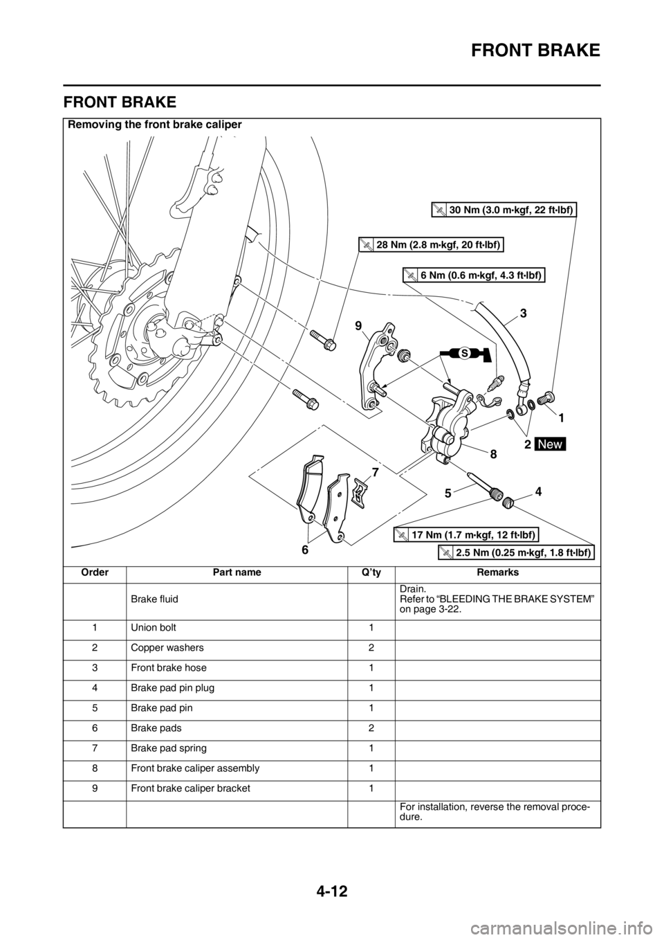
Removing the front brake caliper
Order Part name Q’ty Remarks
Brake fluidDrain.
Refer to “BLEEDING THE BRAKE SYSTEM”
on page 3-22.
1 Union bolt 1
2 Copper washers 2
3 Front brake hose 1
4 Brake pad pin plug 1
5 Brake pad pin 1
6 Brake pads 2
7 Brake pad spring 1
8 Front brake caliper assembly 1
9 Front brake caliper bracket 1
For installation, reverse the removal proce-
dure.
3
9
1
2
8
4
5 7
6
T.R.30 Nm (3.0 mlbf) kgf, 22 ft
T.R.28 Nm (2.8 mlbf) kgf, 20 ft
T.R.17 Nm (1.7 mlbf) kgf, 12 ft
T.R.2.5 Nm (0.25 mlbf) kgf, 1.8 ft
T.R.6 Nm (0.6 mlbf) kgf, 4.3 ft
Page 137 of 362
FRONT BRAKE
4-13
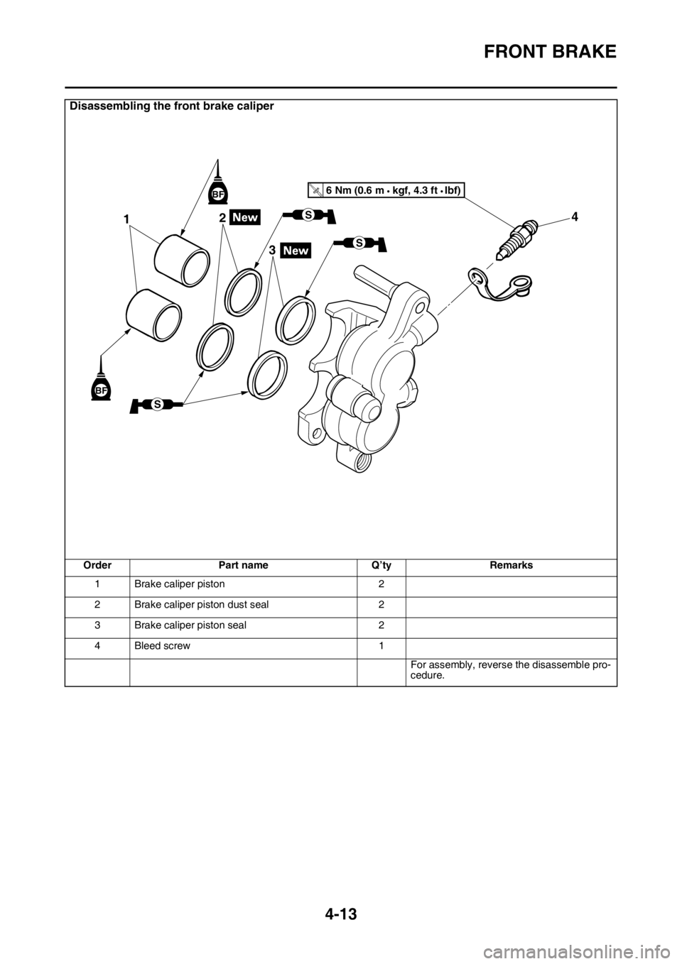
Disassembling the front brake caliper
Order Part name Q’ty Remarks
1 Brake caliper piston 2
2 Brake caliper piston dust seal 2
3 Brake caliper piston seal 2
4 Bleed screw 1
For assembly, reverse the disassemble pro-
cedure.
12
34
S
S
BF
BFT R..
S
6 Nm (0.6 m
kgf, 4.3 ft Ibf)
Page 138 of 362
FRONT BRAKE
4-14
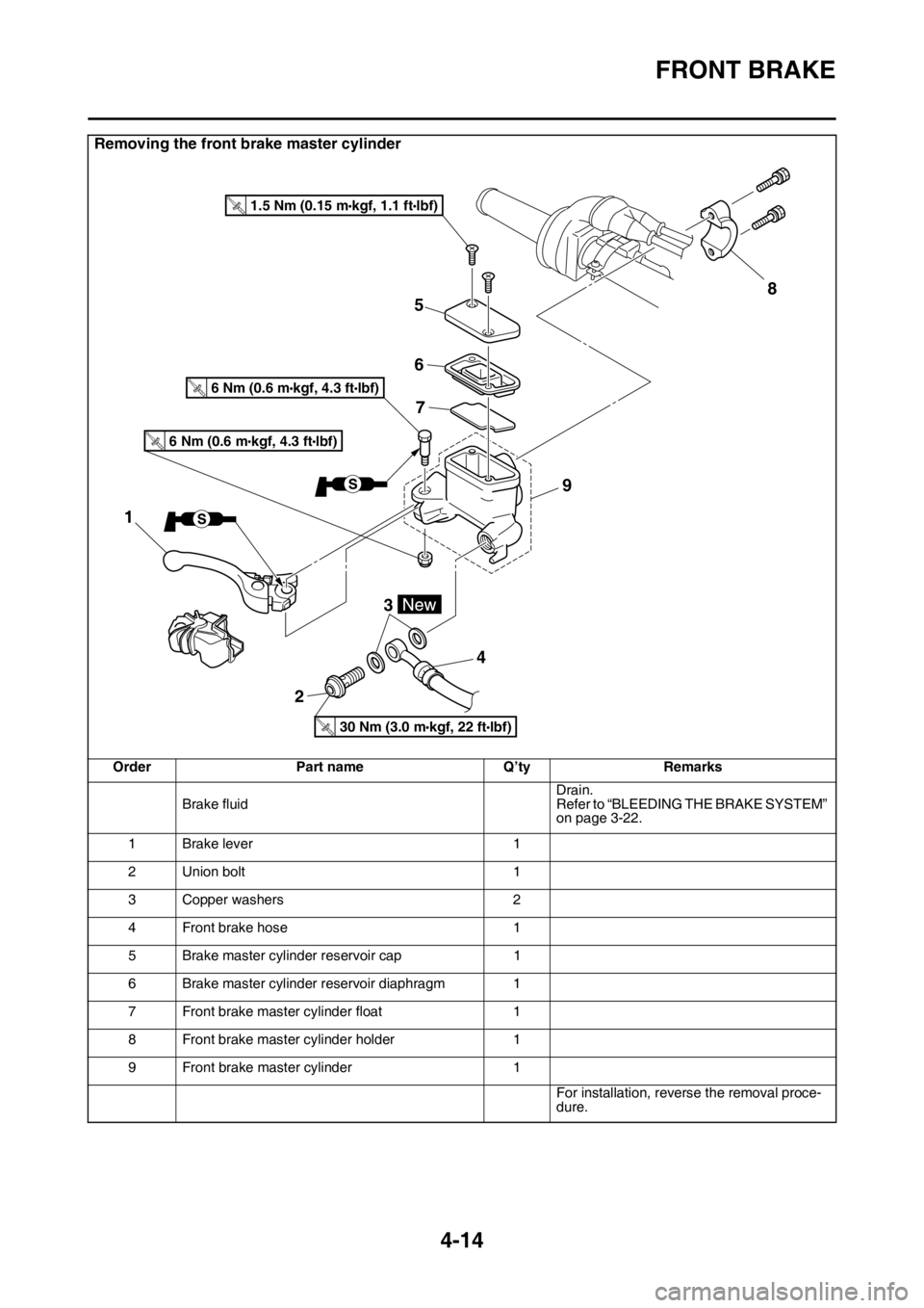
Removing the front brake master cylinder
Order Part name Q’ty Remarks
Brake fluidDrain.
Refer to “BLEEDING THE BRAKE SYSTEM”
on page 3-22.
1 Brake lever 1
2 Union bolt 1
3 Copper washers 2
4 Front brake hose 1
5 Brake master cylinder reservoir cap 1
6 Brake master cylinder reservoir diaphragm 1
7 Front brake master cylinder float 1
8 Front brake master cylinder holder 1
9 Front brake master cylinder 1
For installation, reverse the removal proce-
dure.
5
6
7
23
48
9
1
T.R.30 Nm (3.0 mlbf) kgf, 22 ft
T.R.1.5 Nm (0.15 mlbf) kgf, 1.1 ft
T.R.6 Nm (0.6 mlbf) kgf, 4.3 ft
T.R.6 Nm (0.6 mlbf) kgf, 4.3 ft
Page 139 of 362
FRONT BRAKE
4-15
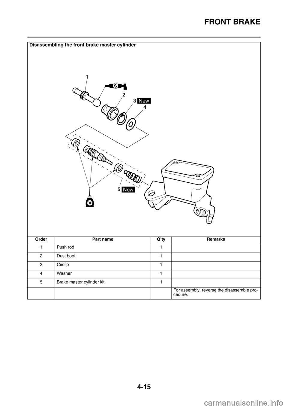
Disassembling the front brake master cylinder
Order Part name Q’ty Remarks
1 Push rod 1
2 Dust boot 1
3 Circlip 1
4Washer 1
5 Brake master cylinder kit 1
For assembly, reverse the disassemble pro-
cedure.
BF
5
4
3
2
1
S
New
New
Page 140 of 362
FRONT BRAKE
4-16
EASB111135INTRODUCTIONEWA
WARNING
If you need to disassemble the disc brake
components, observe the following precau-
tions.
• Never disassemble the brake components
unless absolutely necessary.
• If there is any problem with connections
on the hydraulic brake system, perform
the following jobs.
Disassemble the brake system, drain the
brake fluid, and clean it. After that, add a
suitable amount of brake fluid. Then, bleed
it after reassembly.
• Use only brake fluid for washing brake
components.
• Use new brake fluid for cleaning the brake
components.
• Immediately wipe off the spilled brake fluid
to avoid damage to painted surfaces or
plastic parts.
• Handle brake fluid with special care not to
let it enter your eyes so that you may not
lost your eyesight.
• FIRST AID FOR BRAKE FLUID ENTERING
THE EYES:
• Flush with water for 15 minutes and get
immediate medical attention.
EASB111136CHECKING THE FRONT BRAKE DISC
1. Remove:
• Front wheel
Refer to “FRONT WHEEL” on page 4-3.
2. Check:
• Front brake disc
Damage/galling Replace.
3. Measure:
• Brake disc thickness
Measure the brake disc thickness at a few
different locations.
Out of specification Replace.4. Install:
• Front wheel
Refer to “FRONT WHEEL” on page 4-3.
EASB111137REMOVING THE FRONT BRAKE CALIPER
TIP
Before disassembling the brake caliper, drain
the brake fluid from the entire brake system.
1. Remove:
• Union bolt
• Copper washers
• Brake hose
TIP
Put the end of the brake hose into a container
and pump out the brake fluid.
EASB111138DISASSEMBLING THE FRONT BRAKE CAL-
IPER
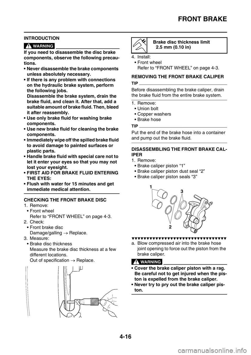
1. Remove:
• Brake caliper piston “1”
• Brake caliper piston dust seal “2”
• Brake caliper piston seals “3”
▼▼▼▼▼▼▼▼▼▼▼▼▼▼▼▼▼▼▼▼▼▼▼▼▼▼▼▼▼▼▼▼
a. Blow compressed air into the brake hose
joint opening to force out the piston from the
brake caliper.
EWA
WARNING
• Cover the brake caliper piston with a rag.
Be careful not to get injured when the pis-
ton is expelled from the brake caliper.
• Never try to pry out the brake caliper pis-
ton.
Brake disc thickness limit
2.5 mm (0.10 in)
3
2
1