YAMAHA YZ450F 2016 Owners Manual
Manufacturer: YAMAHA, Model Year: 2016, Model line: YZ450F, Model: YAMAHA YZ450F 2016Pages: 362, PDF Size: 10.49 MB
Page 151 of 362
REAR BRAKE
4-27
EASB111150REMOVING THE REAR BRAKE CALIPER
TIP
Before disassembling the brake caliper, drain
the brake fluid from the entire brake system.
1. Remove:
• Union bolt
• Copper washers
• Brake hose
TIP
Put the end of the brake hose into a container
and pump out the brake fluid.
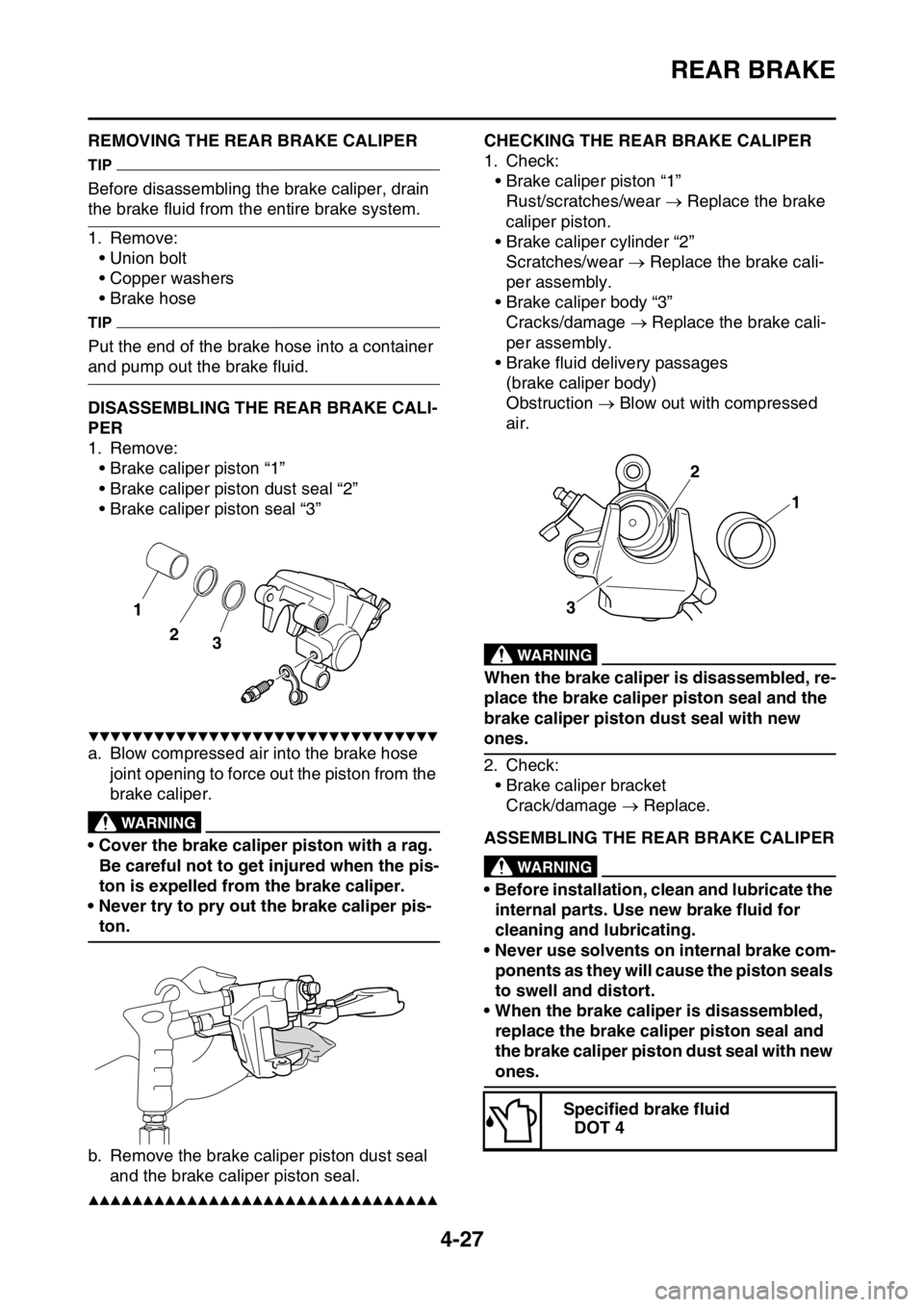
EASB111151DISASSEMBLING THE REAR BRAKE CALI-
PER
1. Remove:
• Brake caliper piston “1”
• Brake caliper piston dust seal “2”
• Brake caliper piston seal “3”
▼▼▼▼▼▼▼▼▼▼▼▼▼▼▼▼▼▼▼▼▼▼▼▼▼▼▼▼▼▼▼▼
a. Blow compressed air into the brake hose
joint opening to force out the piston from the
brake caliper.
EWA
WARNING
• Cover the brake caliper piston with a rag.
Be careful not to get injured when the pis-
ton is expelled from the brake caliper.
• Never try to pry out the brake caliper pis-
ton.
b. Remove the brake caliper piston dust seal
and the brake caliper piston seal.
▲▲▲▲▲▲▲▲▲▲▲▲▲▲▲▲▲▲▲▲▲▲▲▲▲▲▲▲▲▲▲▲
EASB111152CHECKING THE REAR BRAKE CALIPER
1. Check:
• Brake caliper piston “1”
Rust/scratches/wear Replace the brake
caliper piston.
• Brake caliper cylinder “2”
Scratches/wear Replace the brake cali-
per assembly.
• Brake caliper body “3”
Cracks/damage Replace the brake cali-
per assembly.
• Brake fluid delivery passages
(brake caliper body)
Obstruction Blow out with compressed
air.
EWA
WARNING
When the brake caliper is disassembled, re-
place the brake caliper piston seal and the
brake caliper piston dust seal with new
ones.
2. Check:
• Brake caliper bracket
Crack/damage Replace.
EASB111153ASSEMBLING THE REAR BRAKE CALIPEREWA
WARNING
• Before installation, clean and lubricate the
internal parts. Use new brake fluid for
cleaning and lubricating.
• Never use solvents on internal brake com-
ponents as they will cause the piston seals
to swell and distort.
• When the brake caliper is disassembled,
replace the brake caliper piston seal and
the brake caliper piston dust seal with new
ones.
2
3
1
Specified brake fluid
DOT 4
1 2
3
Page 152 of 362
REAR BRAKE
4-28
EASB111154INSTALLING THE BRAKE CALIPER PISTON
1. Clean:
• Brake caliper
• Brake caliper piston seal
• Brake caliper piston dust seal
• Brake caliper piston
Use brake fluid for cleaning.
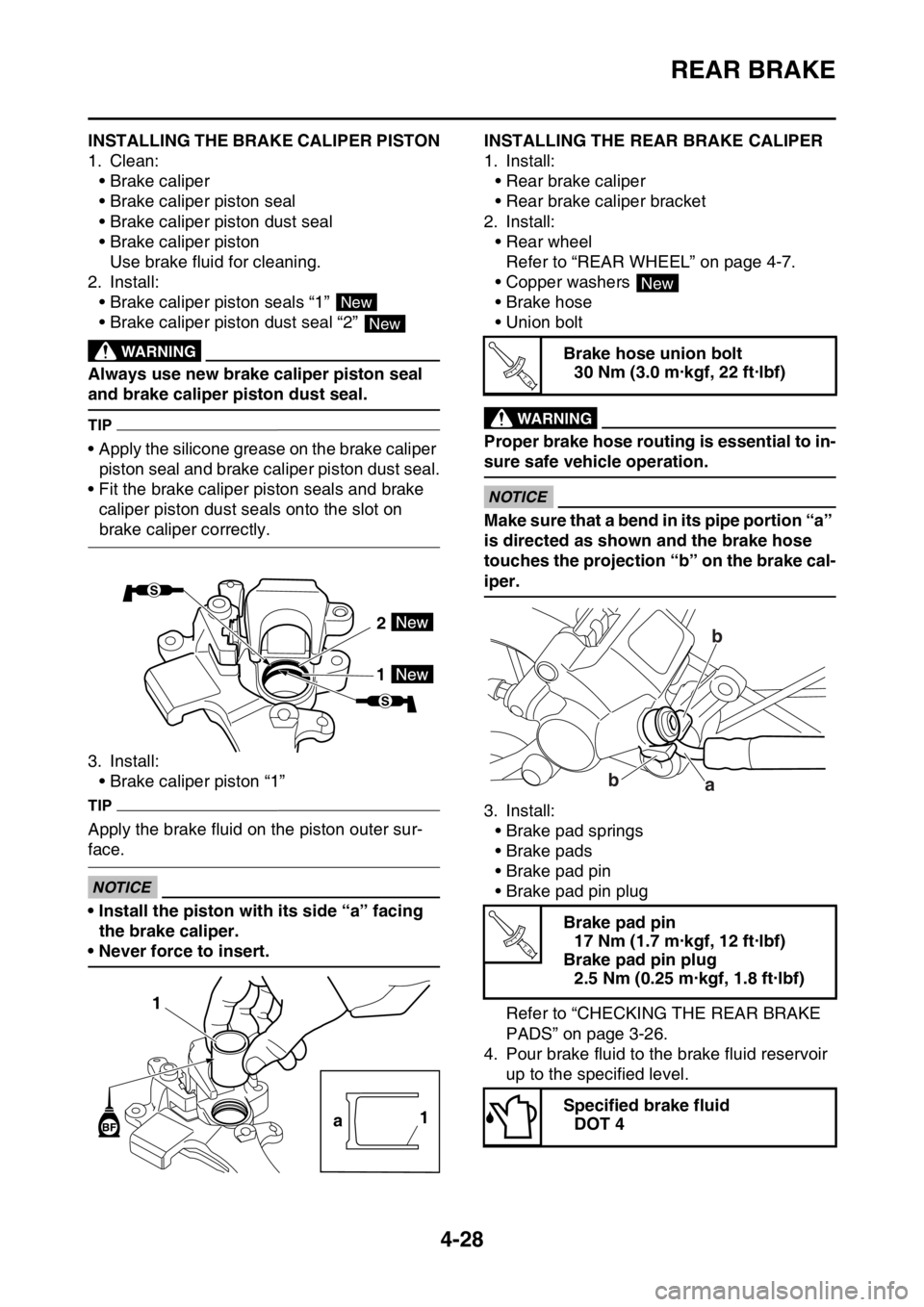
2. Install:
• Brake caliper piston seals “1”
• Brake caliper piston dust seal “2”
EWA
WARNING
Always use new brake caliper piston seal
and brake caliper piston dust seal.
TIP
• Apply the silicone grease on the brake caliper
piston seal and brake caliper piston dust seal.
• Fit the brake caliper piston seals and brake
caliper piston dust seals onto the slot on
brake caliper correctly.
3. Install:
• Brake caliper piston “1”
TIP
Apply the brake fluid on the piston outer sur-
face.
ECA
NOTICE
• Install the piston with its side “a” facing
the brake caliper.
• Never force to insert.
EASB111155INSTALLING THE REAR BRAKE CALIPER
1. Install:
• Rear brake caliper
• Rear brake caliper bracket
2. Install:
• Rear wheel
Refer to “REAR WHEEL” on page 4-7.
• Copper washers
• Brake hose
• Union bolt
EWA
WARNING
Proper brake hose routing is essential to in-
sure safe vehicle operation.
ECA
NOTICE
Make sure that a bend in its pipe portion “a”
is directed as shown and the brake hose
touches the projection “b” on the brake cal-
iper.
3. Install:
• Brake pad springs
• Brake pads
• Brake pad pin
• Brake pad pin plug
Refer to “CHECKING THE REAR BRAKE
PADS” on page 3-26.
4. Pour brake fluid to the brake fluid reservoir
up to the specified level.
EWA
New
New
2
1
1
a1
Brake hose union bolt
30 Nm (3.0 m·kgf, 22 ft·lbf)
Brake pad pin
17 Nm (1.7 m·kgf, 12 ft·lbf)
Brake pad pin plug
2.5 Nm (0.25 m·kgf, 1.8 ft·lbf)
Specified brake fluid
DOT 4
New
T R..
b
b
a
T R..
Page 153 of 362
REAR BRAKE
4-29
WARNING
• Use only the designated brake fluid. Other
brake fluids may cause the rubber seals to
deteriorate, causing leakage and poor
brake performance.
• Refill with the same type of brake fluid that
is already in the system. Mixing brake flu-
ids may result in a harmful chemical reac-
tion, leading to poor brake performance.
• When refilling, be careful that water does
not enter the brake fluid reservoir. Water
will significantly lower the boiling point of
the brake fluid and could cause vapor
lock.
ECA
NOTICE
Brake fluid may damage painted surfaces
and plastic parts. Therefore, always clean
up any spilt brake fluid immediately.
5. Bleed:
• Brake system
Refer to “BLEEDING THE BRAKE SYS-
TEM” on page 3-22.
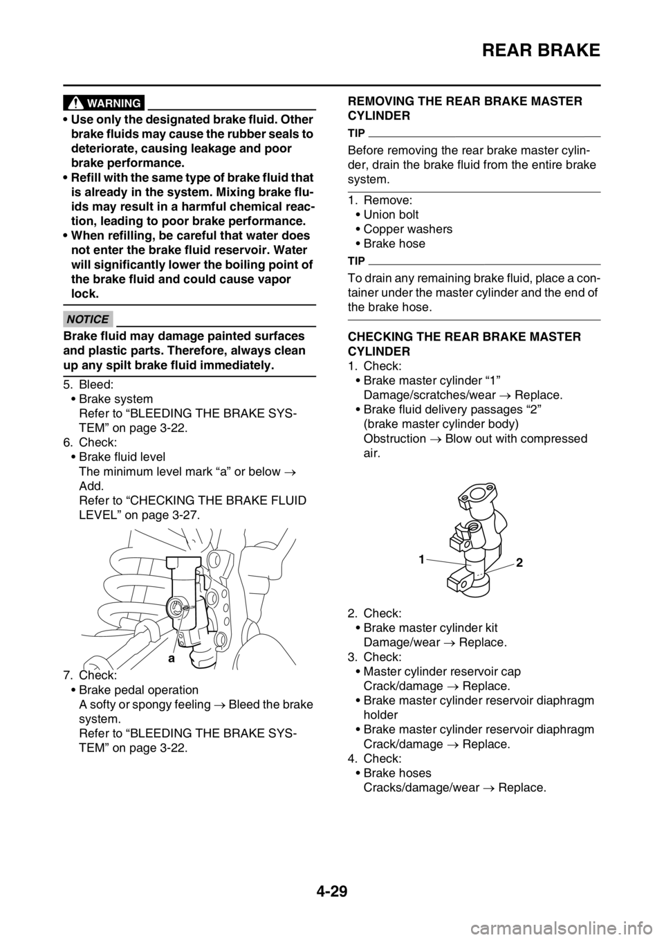
6. Check:
• Brake fluid level
The minimum level mark “a” or below
Add.
Refer to “CHECKING THE BRAKE FLUID
LEVEL” on page 3-27.
7. Check:
• Brake pedal operation
A softy or spongy feeling Bleed the brake
system.
Refer to “BLEEDING THE BRAKE SYS-
TEM” on page 3-22.
EASB111156REMOVING THE REAR BRAKE MASTER
CYLINDER
TIP
Before removing the rear brake master cylin-
der, drain the brake fluid from the entire brake
system.
1. Remove:
• Union bolt
• Copper washers
• Brake hose
TIP
To drain any remaining brake fluid, place a con-
tainer under the master cylinder and the end of
the brake hose.
EASB111157CHECKING THE REAR BRAKE MASTER
CYLINDER
1. Check:
• Brake master cylinder “1”
Damage/scratches/wear Replace.
• Brake fluid delivery passages “2”
(brake master cylinder body)
Obstruction Blow out with compressed
air.
2. Check:
• Brake master cylinder kit
Damage/wear Replace.
3. Check:
• Master cylinder reservoir cap
Crack/damage Replace.
• Brake master cylinder reservoir diaphragm
holder
• Brake master cylinder reservoir diaphragm
Crack/damage Replace.
4. Check:
• Brake hoses
Cracks/damage/wear Replace.
a
1
2
Page 154 of 362
REAR BRAKE
4-30
EASB111158ASSEMBLING THE REAR BRAKE MASTER
CYLINDER
EWA
WARNING
• Before installation, all internal brake com-
ponents should be cleaned and lubricated
with clean or new brake fluid.
• Never use solvents on internal brake com-
ponents.
1. Wash the brake master cylinder and the
brake master cylinder kit with brake fluid.
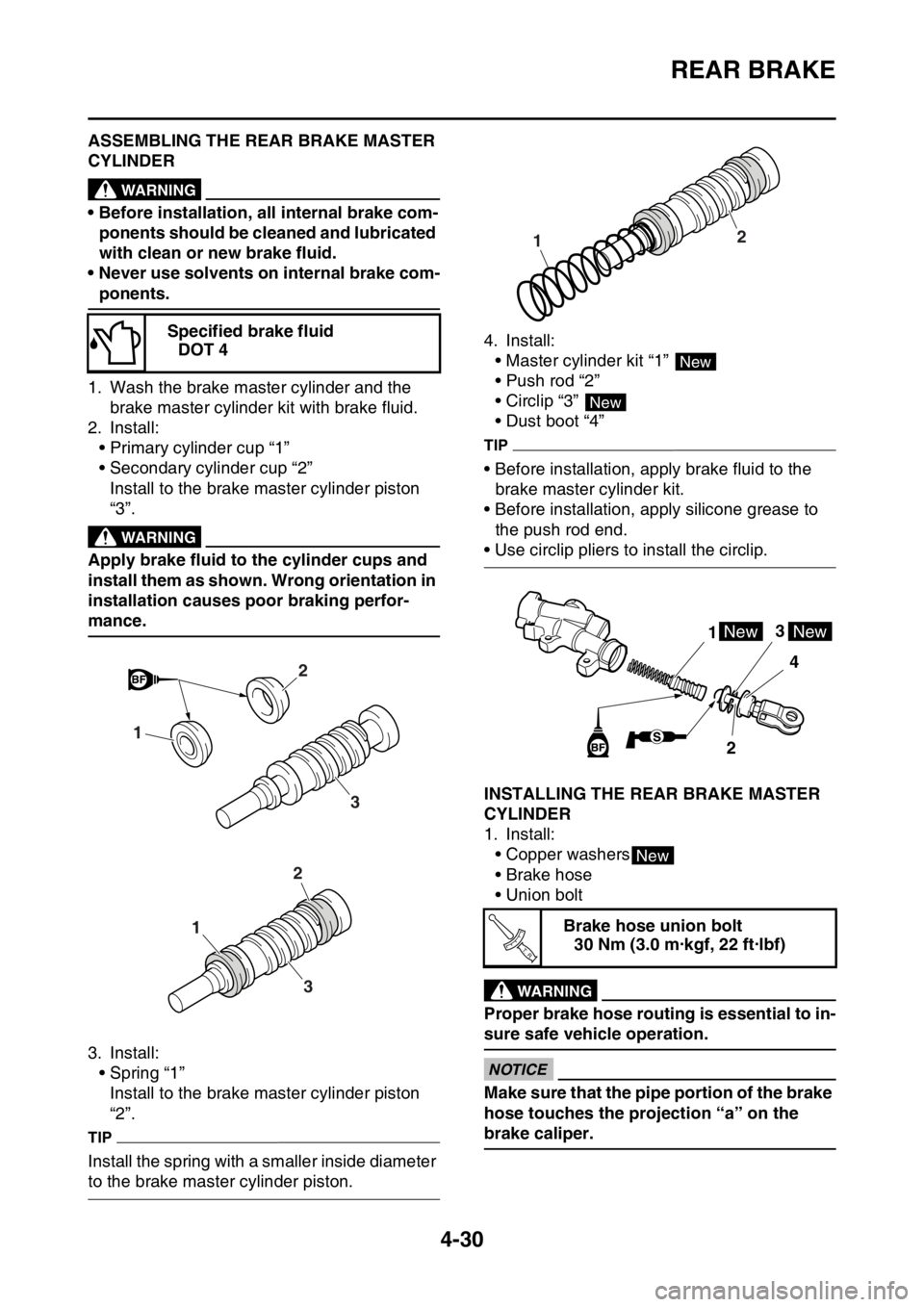
2. Install:
• Primary cylinder cup “1”
• Secondary cylinder cup “2”
Install to the brake master cylinder piston
“3”.
EWA
WARNING
Apply brake fluid to the cylinder cups and
install them as shown. Wrong orientation in
installation causes poor braking perfor-
mance.
3. Install:
• Spring “1”
Install to the brake master cylinder piston
“2”.
TIP
Install the spring with a smaller inside diameter
to the brake master cylinder piston.4. Install:
• Master cylinder kit “1”
• Push rod “2”
• Circlip “3”
• Dust boot “4”
TIP
• Before installation, apply brake fluid to the
brake master cylinder kit.
• Before installation, apply silicone grease to
the push rod end.
• Use circlip pliers to install the circlip.
EASB111159INSTALLING THE REAR BRAKE MASTER
CYLINDER
1. Install:
• Copper washers
• Brake hose
• Union bolt
EWA
WARNING
Proper brake hose routing is essential to in-
sure safe vehicle operation.
ECA
NOTICE
Make sure that the pipe portion of the brake
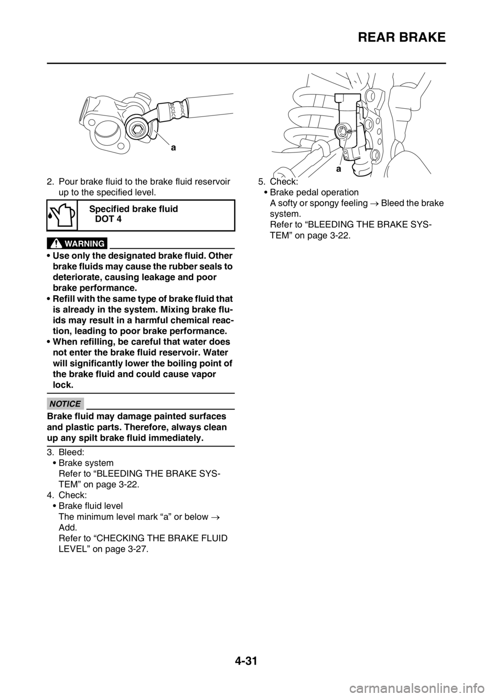
hose touches the projection “a” on the
brake caliper. Specified brake fluid
DOT 4
2
3
1
2
3
1Brake hose union bolt
30 Nm (3.0 m·kgf, 22 ft·lbf)
12
New
New
13
4
2NewNew
New
T R..
Page 155 of 362
REAR BRAKE
4-31
2. Pour brake fluid to the brake fluid reservoir
up to the specified level.
EWA
WARNING
• Use only the designated brake fluid. Other
brake fluids may cause the rubber seals to
deteriorate, causing leakage and poor
brake performance.
• Refill with the same type of brake fluid that
is already in the system. Mixing brake flu-
ids may result in a harmful chemical reac-
tion, leading to poor brake performance.
• When refilling, be careful that water does
not enter the brake fluid reservoir. Water
will significantly lower the boiling point of
the brake fluid and could cause vapor
lock.
ECA
NOTICE
Brake fluid may damage painted surfaces
and plastic parts. Therefore, always clean
up any spilt brake fluid immediately.
3. Bleed:
• Brake system
Refer to “BLEEDING THE BRAKE SYS-
TEM” on page 3-22.
4. Check:
• Brake fluid level
The minimum level mark “a” or below
Add.
Refer to “CHECKING THE BRAKE FLUID
LEVEL” on page 3-27.5. Check:
• Brake pedal operation
A softy or spongy feeling Bleed the brake
system.
Refer to “BLEEDING THE BRAKE SYS-
TEM” on page 3-22. Specified brake fluid
DOT 4
a
a
Page 156 of 362
HANDLEBAR
4-32
EASB111160
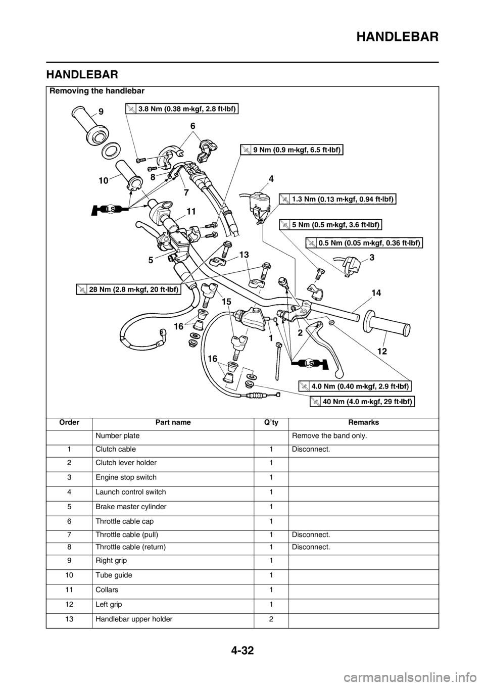
HANDLEBAR
Removing the handlebar
Order Part name Q’ty Remarks
Number plate Remove the band only.
1 Clutch cable 1 Disconnect.
2 Clutch lever holder 1
3 Engine stop switch 1
4 Launch control switch 1
5 Brake master cylinder 1
6 Throttle cable cap 1
7 Throttle cable (pull) 1 Disconnect.
8 Throttle cable (return) 1 Disconnect.
9 Right grip 1
10 Tube guide 1
11 Collars 1
12 Left grip 1
13 Handlebar upper holder 2
Page 157 of 362
HANDLEBAR
4-33
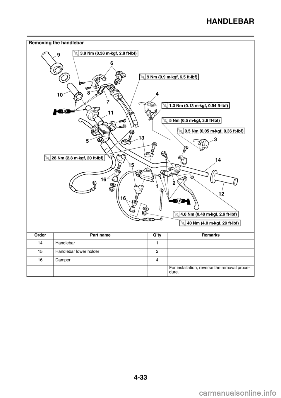
14 Handlebar 1
15 Handlebar lower holder 2
16 Damper 4
For installation, reverse the removal proce-
dure.
Removing the handlebar
Order Part name Q’ty Remarks
Page 158 of 362
HANDLEBAR
4-34
EASB111161REMOVING THE HANDLEBAR
1. Stand the vehicle upright on a level surface.
EWA13120
WARNING
Securely support the vehicle so that there is
no danger of it falling over.
2. Remove:
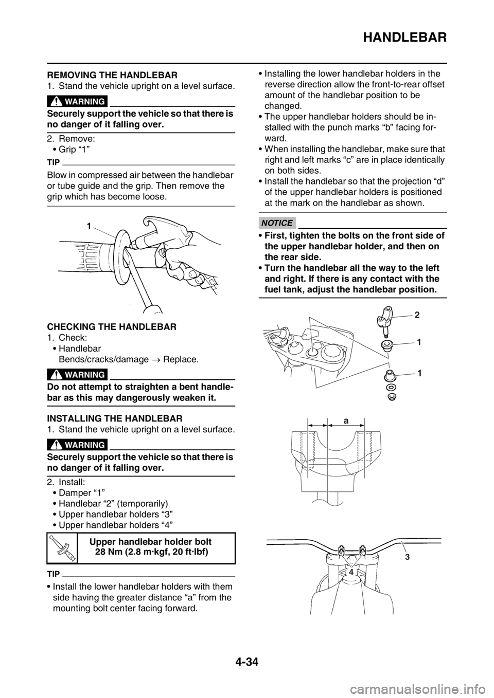
• Grip “1”
TIP
Blow in compressed air between the handlebar
or tube guide and the grip. Then remove the
grip which has become loose.
EASB111162CHECKING THE HANDLEBAR
1. Check:
• Handlebar
Bends/cracks/damage Replace.
EWA
WARNING
Do not attempt to straighten a bent handle-
bar as this may dangerously weaken it.
EASB111163INSTALLING THE HANDLEBAR
1. Stand the vehicle upright on a level surface.
EWA13120
WARNING
Securely support the vehicle so that there is
no danger of it falling over.
2. Install:
• Damper “1”
• Handlebar “2” (temporarily)
• Upper handlebar holders “3”
• Upper handlebar holders “4”
TIP
• Install the lower handlebar holders with them
side having the greater distance “a” from the
mounting bolt center facing forward.• Installing the lower handlebar holders in the
reverse direction allow the front-to-rear offset
amount of the handlebar position to be
changed.
• The upper handlebar holders should be in-
stalled with the punch marks “b” facing for-
ward.
• When installing the handlebar, make sure that
right and left marks “c” are in place identically
on both sides.
• Install the handlebar so that the projection “d”
of the upper handlebar holders is positioned
at the mark on the handlebar as shown.
ECA14250
NOTICE
• First, tighten the bolts on the front side of
the upper handlebar holder, and then on
the rear side.
• Turn the handlebar all the way to the left
and right. If there is any contact with the
fuel tank, adjust the handlebar position.
Upper handlebar holder bolt
28 Nm (2.8 m·kgf, 20 ft·lbf)
T R..
2
1
1
a
3
4
Page 159 of 362
HANDLEBAR
4-35
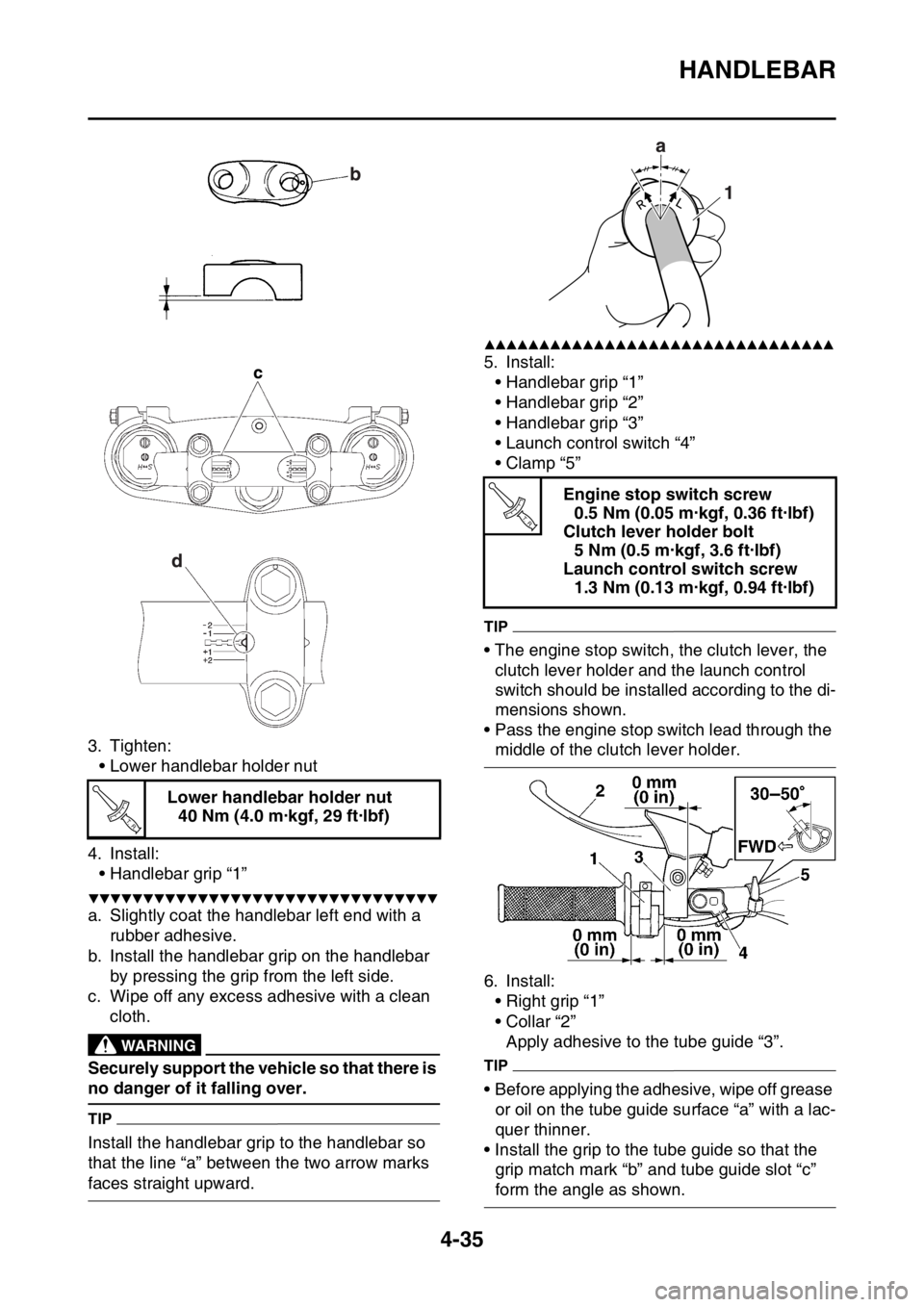
3. Tighten:
• Lower handlebar holder nut
4. Install:
• Handlebar grip “1”
▼▼▼▼▼▼▼▼▼▼▼▼▼▼▼▼▼▼▼▼▼▼▼▼▼▼▼▼▼▼▼▼
a. Slightly coat the handlebar left end with a
rubber adhesive.
b. Install the handlebar grip on the handlebar
by pressing the grip from the left side.
c. Wipe off any excess adhesive with a clean
cloth.
EWA13120
WARNING
Securely support the vehicle so that there is
no danger of it falling over.
TIP
Install the handlebar grip to the handlebar so
that the line “a” between the two arrow marks
faces straight upward.
▲▲▲▲▲▲▲▲▲▲▲▲▲▲▲▲▲▲▲▲▲▲▲▲▲▲▲▲▲▲▲▲
5. Install:
• Handlebar grip “1”
• Handlebar grip “2”
• Handlebar grip “3”
• Launch control switch “4”
•Clamp “5”
TIP
• The engine stop switch, the clutch lever, the
clutch lever holder and the launch control
switch should be installed according to the di-
mensions shown.
• Pass the engine stop switch lead through the
middle of the clutch lever holder.
6. Install:
• Right grip “1”
• Collar “2”
Apply adhesive to the tube guide “3”.
TIP
• Before applying the adhesive, wipe off grease
or oil on the tube guide surface “a” with a lac-
quer thinner.
• Install the grip to the tube guide so that the
grip match mark “b” and tube guide slot “c”
form the angle as shown. Lower handlebar holder nut
40 Nm (4.0 m·kgf, 29 ft·lbf)
T R..
Engine stop switch screw
0.5 Nm (0.05 m·kgf, 0.36 ft·lbf)
Clutch lever holder bolt
5 Nm (0.5 m·kgf, 3.6 ft·lbf)
Launch control switch screw
1.3 Nm (0.13 m·kgf, 0.94 ft·lbf)
T R..
Page 160 of 362
HANDLEBAR
4-36
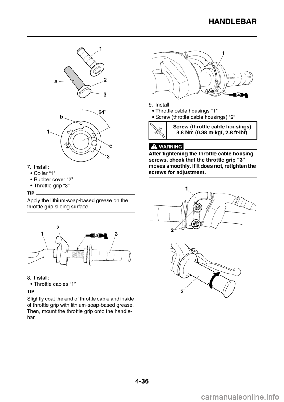
7. Install:
• Collar “1”
• Rubber cover “2”
• Throttle grip “3”
TIP
Apply the lithium-soap-based grease on the
throttle grip sliding surface.
8. Install:
• Throttle cables “1”
TIP
Slightly coat the end of throttle cable and inside
of throttle grip with lithium-soap-based grease.
Then, mount the throttle grip onto the handle-
bar.9. Install:
• Throttle cable housings “1”
• Screw (throttle cable housings) “2”
EWA1DX5001
WARNING
After tightening the throttle cable housing
screws, check that the throttle grip “3”
moves smoothly. If it does not, retighten the
screws for adjustment.
64
1b
c
3 64
Screw (throttle cable housings)
3.8 Nm (0.38 m·kgf, 2.8 ft·lbf)
T R..