engine YAMAHA YZF-R1M 2017 Owner's Manual
[x] Cancel search | Manufacturer: YAMAHA, Model Year: 2017, Model line: YZF-R1M, Model: YAMAHA YZF-R1M 2017Pages: 130, PDF Size: 9.99 MB
Page 38 of 130

Instrument and control functions
4-17
1
2
34
5
6
7
8
9
10
11
12
TIP
TCS can only be turned on or off
via the main screen using the
mode switch.
When TCS has been turned off,
TCS, SCS, LCS, and LIF will be
set to OFF and cannot be adjust-
ed. When TCS is turned on again,
these related-traction control func-
tions will return to their previoussetting levels.
SCS
SCS can be set to OFF, 1, 2, and 3.
OFF turns the slide control system off,
setting level 1 provides the least amount of system intervention, and set-
ting level 3 provides the greatest
amount of system intervention.
LCS
LCS can be set to 1, 2, or OFF. Setting
level 2 more strongly controls power
engine output, while setting level 1 ap-
plies less system intervention. OFF dis-
ables the LCS function from the
selected YRC mode (the LCS icon will
not appear and the launch control func-
tion cannot be activated).
When LCS has been set to level 1 or 2
for the selected YRC mode, the LCS in-
dicator on the main screen will appear
in a grey color to indicate that LCS isavailable. When the launch control sys-
tem has been activated (made ready
for use via the mode switch), the LCS
indicator will turn white.
TIPLCS works in conjunction with the LIF
system. LCS cannot be used if LIF isturned off.
QSS
QSS can be set to 1, 2, or OFF. Setting
level 1 gives the fastest shifts, while
setting level 2 gives slightly smoother
shifts. OFF turns the system off entire-
ly, and the clutch lever must then be
used when making upshifts.TIPTurning the QSS on or off does not af-
fect any other systems nor is QSS af-
fected by the settings of any othersystem.
LIF
LIF can be set to 1, 2, 3, or OFF. Setting
level 3 most strongly reduces wheel lift,
and setting level 1 provides the least
amount of system intervention. OFF
1. System intervention
2. Lean angle
1
TCS
2
1 5
4 3
2 6 9
8 7
1. System intervention
2. Sideward slide
1 3
2
1
SCS
2
BX4-9-E0.book 17 ページ 2016年12月1日 木曜日 午後8時7分
Page 43 of 130

Instrument and control functions
4-22
1
2
345
6
7
8
9
10
11
12
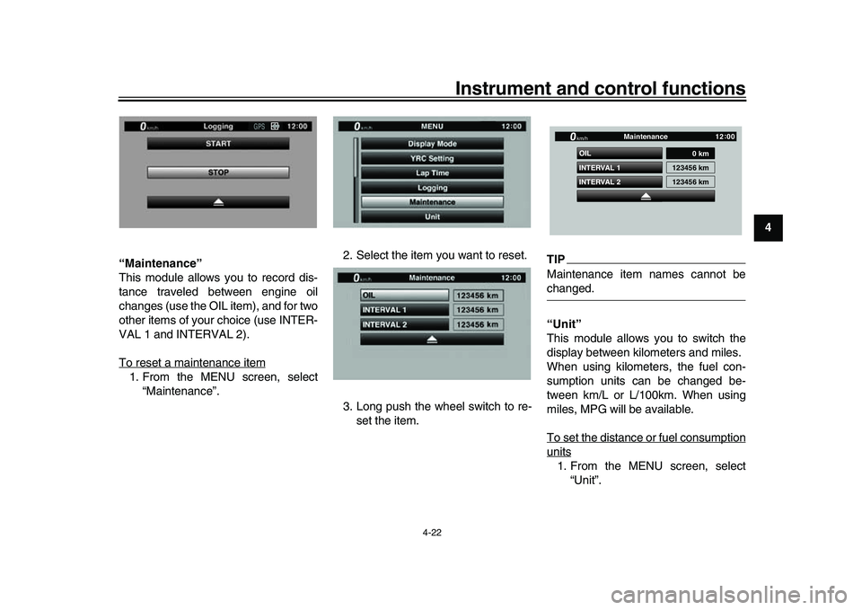
“Maintenance”
This module allows you to record dis-
tance traveled between engine oil
changes (use the OIL item), and for two
other items of your choice (use INTER-
VAL 1 and INTERVAL 2).
To reset a maintenance item
1. From the MENU screen, select
“Maintenance”. 2. Select the item you want to reset.
3. Long push the wheel switch to re-
set the item.
TIPMaintenance item names cannot bechanged.
“Unit”
This module allows you to switch the
display between kilometers and miles.
When using kilometers, the fuel con-
sumption units can be changed be-
tween km/L or L/100km. When using
miles, MPG will be available.
To set the distance or fuel consumptionunits1. From the MENU screen, select“Unit”.
GPS
INTERVAL 2 OIL
INTERVAL 1
0 km
123456 km
123456 km
Maintenance
km/h
GPS
12 :
00
BX4-9-E0.book 22 ページ 2016年12月1日 木曜日 午後8時7分
Page 55 of 130

Instrument and control functions
4-34
1
2
345
6
7
8
9
10
11
12
TIPThe fuel tank cap cannot be closed un-
less the key is in the lock. In addition,
the key cannot be removed if the cap isnot properly closed and locked.
WARNING
EWA11092
Make sure that the fuel tank cap is
properly closed after filling fuel.Leaking fuel is a fire hazard.
EAU13222
FuelMake sure there is sufficient gasoline in
the tank.
WARNING
EWA10882
Gasoline and gasoline vapors are
extremely flammable. To avoid fires
and explosions and to reduce the
risk of injury when refueling, followthese instructions. 1. Before refueling, turn off the en- gine and be sure that no one is sit-
ting on the vehicle. Never refuel
while smoking, or while in the vi-
cinity of sparks, open flames, or
other sources of ignition such as
the pilot lights of water heaters and
clothes dryers.
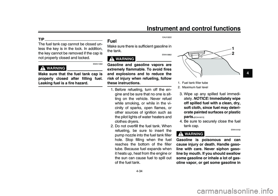
2. Do not overfill the fuel tank. When refueling, be sure to insert the
pump nozzle into the fuel tank filler
hole. Stop filling when the fuel
reaches the bottom of the filler
tube. Because fuel expands when
it heats up, heat from the engine or
the sun can cause fuel to spill out
of the fuel tank. 3. Wipe up any spilled fuel immedi-
ately. NOTICE: Immediately wipe
off spilled fuel with a clean, dry,
soft cloth, since fuel may deteri-
orate painted surfaces or plastic
parts.
[ECA10072]
4. Be sure to securely close the fuel tank cap.
WARNING
EWA15152
Gasoline is poisonous and can
cause injury or death. Handle gaso-
line with care. Never siphon gaso-
line by mouth. If you should swallow
some gasoline or inhale a lot of gas-
oline vapor, or get some gasoline in1. Fuel tank filler tube
2. Maximum fuel level
1
2
BX4-9-E0.book 34 ページ 2016年12月1日 木曜日 午後8時7分
Page 56 of 130

Instrument and control functions
4-35
1
2
34
5
6
7
8
9
10
11
12 your eyes, see your doctor immedi-
ately. If gasoline spills on your skin,
wash with soap and water. If gaso-
line spills on your clothing, change
your clothes.
EAU75320
NOTICE
ECA11401
Use only unleaded gasoline. The use
of leaded gasoline will cause severe
damage to internal engine parts,
such as the valves and piston rings,as well as to the exhaust system.
TIP
This mark identifies the recom-
mended fuel for this vehicle as
specified by European regulation
(EN228).
Check that gasoline nozzle has thesame identifier when fueling.
Your Yamaha engine has been de-
signed to use premium unleaded gaso-
line with a research octane number of
95 or higher. If knocking (or pinging) oc-
curs, use a gasoline of a different
brand. Use of unleaded fuel will extend
spark plug life and reduce maintenance
costs.
Gasohol
There are two types of gasohol: gaso- hol containing ethanol and that contain-
ing methanol. Gasohol containing
ethanol can be used if the ethanol con-
tent does not exceed 10% (E10). Gas-
ohol containing methanol is not
recommended by Yamaha because it
can cause damage to the fuel system
or vehicle performance problems.
Recommended fuel:
Premium unleaded gasoline (Gaso-
hol [E10] acceptable)
Fuel tank capacity: 17 L (4.5 US gal, 3.7 Imp.gal)
Fuel reserve amount (when the fuel
level warning light comes on):
3.0 L (0.79 US gal, 0.66 Imp.gal)
E10
BX4-9-E0.book 35 ページ 2016年12月1日 木曜日 午後8時7分
Page 57 of 130

Instrument and control functions
4-36
1
2
345
6
7
8
9
10
11
12
EAU58081
Fuel tank breat her hose and
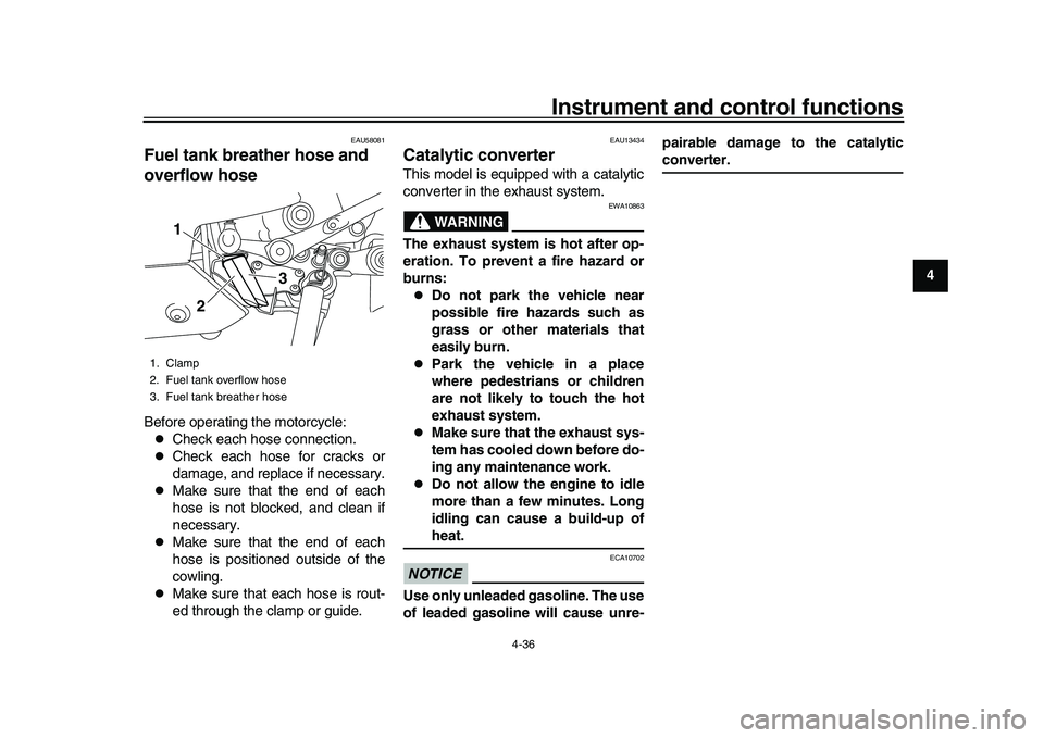
overflow hoseBefore operating the motorcycle:
Check each hose connection.
Check each hose for cracks or
damage, and replace if necessary.
Make sure that the end of each
hose is not blocked, and clean if
necessary.
Make sure that the end of each
hose is positioned outside of the
cowling.
Make sure that each hose is rout-
ed through the clamp or guide.
EAU13434
Catalytic converterThis model is equipped with a catalytic
converter in the exhaust system.
WARNING
EWA10863
The exhaust system is hot after op-
eration. To prevent a fire hazard or
burns:
Do not park the vehicle near
possible fire hazards such as
grass or other materials that
easily burn.
Park the vehicle in a place
where pedestrians or children
are not likely to touch the hot
exhaust system.
Make sure that the exhaust sys-
tem has cooled down before do-
ing any maintenance work.
Do not allow the engine to idle
more than a few minutes. Long
idling can cause a build-up ofheat.
NOTICE
ECA10702
Use only unleaded gasoline. The use
of leaded gasoline will cause unre- pairable damage to the catalytic
converter.
1. Clamp
2. Fuel tank overflow hose
3. Fuel tank breather hose
1
2
3
BX4-9-E0.book 36 ページ 2016年12月1日 木曜日 午後8時7分
Page 60 of 130

Instrument and control functions
4-39
1
2
34
5
6
7
8
9
10
11
12 smartphone or tablet.
4. Connect to the wireless network “YAMAHA MOTOR CCU” by in-
putting the CCU serial number as
the password.
5. Install the seat cover and GPS re- ceiver to the original position, and
then install the screws.
TIPSince all CCU-equipped models put out
a similarly named wireless network,
have only one vehicle turned on at atime to avoid confusion.
EAU66920
Document storageA document storage space is located
under panel C. (See page 7-9.)
When storing the owner’s manual or
vehicle registration and insurance doc-
uments in the document storage space,
be sure to wrap them in a plastic bag so
that they will not get wet. When wash-
ing the vehicle, avoid letting water enter
the document storage space.NOTICE
ECA22540
Do not place heat-sensitive items in
the document storage space. This
space can get hot when the engine
is running or when the vehicle is in
direct sunlight.
1. Document storage space
2. Panel C
1
2
BX4-9-E0.book 39 ページ 2016年12月1日 木曜日 午後8時7分
Page 67 of 130

Instrument and control functions
4-46
1
2
345
6
7
8
9
10
11
12
3. Tighten the locknut to the specified
torque. NOTICE: Always tighten
the locknut against the adjust-
ing ring, and then tighten the
locknut to the specified
torque.
[ECA22760] EAU67050
EXUP systemThis model is equipped with Yamaha’s
EXUP (EXhaust Ultimate Power valve)
system. This system boosts engine
power by means of a valve that controls
exhaust flow within the exhaust cham-
ber.NOTICE
ECA15611
The EXUP system has been set and
extensively tested at the Yamaha
factory. Changing these settings
without sufficient technical knowl-
edge may result in poor perfor-mance of or damage to the engine.
EAU70641
Auxiliary DC connectorThis vehicle is equipped with an auxilia-
ry DC connector. Consult your Yamaha
dealer before installing any accesso-
ries.
Spring preload:
Minimum (soft): Distance A = 0 mm (0.00 in)
Standard:
Distance A = 4 mm (0.16 in)
Maximum (hard): Distance A = 9 mm (0.35 in)
Tightening torque: Locknut: 25 N·m (2.5 kgf·m, 18 lb·ft)
BX4-9-E0.book 46 ページ 2016年12月1日 木曜日 午後8時7分
Page 68 of 130

Instrument and control functions
4-47
1
2
34
5
6
7
8
9
10
11
12
EAU15306
SidestandThe sidestand is located on the left side
of the frame. Raise the sidestand or
lower it with your foot while holding the
vehicle upright.TIPThe built-in sidestand switch is part of
the ignition circuit cut-off system, which
cuts the ignition in certain situations.
(See the following section for an expla-
nation of the ignition circuit cut-off sys-tem.)
WARNING
EWA10242
The vehicle must not be ridden with
the sidestand down, or if the sides-
tand cannot be properly moved up
(or does not stay up), otherwise the
sidestand could contact the ground
and distract the operator, resulting
in a possible loss of control.
Yamaha’s ignition circuit cut-off
system has been designed to assist
the operator in fulfilling the respon-
sibility of raising the sidestand be-
fore starting off. Therefore, check
this system regularly and have a Yamaha dealer repair it if it does not
function properly.
EAU57950
Ignition circuit
cut-off systemThe ignition circuit cut-off system (com-
prising the sidestand switch, clutch
switch and neutral switch) has the fol-
lowing functions.
It prevents starting when the trans-
mission is in gear and the sides-
tand is up, but the clutch lever is
not pulled.
It prevents starting when the trans-
mission is in gear and the clutch le-
ver is pulled, but the sidestand is
still down.
It cuts the running engine when the
transmission is in gear and the sid-
estand is moved down.
Periodically check the operation of the
ignition circuit cut-off system according
to the following procedure.
BX4-9-E0.book 47 ページ 2016年12月1日 木曜日 午後8時7分
Page 69 of 130

Instrument and control functions
4-48
1
2
345
6
7
8
9
10
11
12
With the engine turned off:
1. Move the sidestand down.
2. Make sure that the start/engine stop switch is set to “ ”.
3. Turn the key on.
4. Shift the transmission into the neutral position.
5. Push the “ ” side of the start/engine stop switch.
Does the engine start?
With the engine still running:
6. Move the sidestand up.
7. Keep the clutch lever pulled.
8. Shift the transmission into gear.
9. Move the sidestand down.
Does the engine stall?
After the engine has stalled:
10. Move the sidestand up.
11. Keep the clutch lever pulled.
12. Push the “ ” side of the start/engine stop switch.
Does the engine start?
The system is OK. The motorcycle can be ridden.
YES NO YES NO YES NO
The neutral switch may not be working correctly.
The motorcycle should not be ridden until
checked by a Yamaha dealer.
The clutch switch may not be working correctly.
The motorcycle should not be ridden until
checked by a Yamaha dealer.The sidestand switch may not be working correctly.
The motorcycle should not be ridden until
checked by a Yamaha dealer.If a malfunction is noted, have a Yamaha
dealer check the system before riding.
WARNING
BX4-9-E0.book 48 ページ 2016年12月1日 木曜日 午後8時7分
Page 70 of 130

5-1
1
2
3
45
6
7
8
9
10
11
12
For your safety – pre-operation checks
EAU15599
Inspect your vehicle each time you use it to make sure the vehi cle is in safe operating condition. Always follow the inspection
and maintenance procedures and schedules described in the Owner’s Manual.
WARNING
EWA11152
Failure to inspect or maintain the vehicle properly increases the possibility of an accident or equipment damage.
Do not operate the vehicle if you find any problem. If a problem cannot be corrected by the procedures provided inthis manual, have the vehicle inspected by a Yamaha dealer.
Before using this vehicle, check the following points:
ITEM CHECKS PAGE
Fuel Check fuel level in fuel tank.
Refuel if necessary.
Check fuel line for leakage.
Check fuel tank breather hose and overflow hose for obstructions, cracks or
damage, and check hose connections. 4-34, 4-36
Engine oil Check oil level in engine.
If necessary, add recommended oil to specified level.
Check vehicle for oil leakage. 7-13
Coolant Check coolant level in reservoir.
If necessary, add recommended coolant to specified level.
Check cooling system for leakage. 7-16
Front brake Check operation.
If soft or spongy, have Yamaha dealer bleed hydraulic system.
Check brake pads for wear.
Replace if necessary.
Check fluid level in reservoir.
If necessary, add specified brake fluid to specified level.
Check hydraulic system for leakage. 7-25
BX4-9-E0.book 1 ページ 2016年12月1日 木曜日 午後8時7分