warning light YAMAHA YZF-R1M 2020 Owners Manual
[x] Cancel search | Manufacturer: YAMAHA, Model Year: 2020, Model line: YZF-R1M, Model: YAMAHA YZF-R1M 2020Pages: 136, PDF Size: 16.15 MB
Page 8 of 136
Table of contentsSafety information ............................ 1-1
Description ....................................... 2-1
Left view ......................................... 2-1
Right view ....................................... 2-2
Controls and instruments ............... 2-3
Special features ............................... 3-1
YRC (Yamaha Ride Control) ........... 3-1
Glossary ......................................... 3-5
YRC functions visual guide ............ 3-6
Instrument an d control functions ... 4-1
Immobilizer system......................... 4-1
Main switch/steering lock............... 4-2
Handlebar switches ........................ 4-3
Indicator lights and warning
lights............................................ 4-5
Display ............................................ 4-9
MENU screen ............................... 4-15
Clutch lever .................................. 4-32
Shift pedal .................................... 4-32
Brake lever.................................... 4-33
Brake pedal .................................. 4-33
Brake control system (BC)............ 4-33
Fuel tank cap ................................ 4-35
Fuel ............................................... 4-35
Fuel tank overflow hose ............... 4-37
Catalytic converter ....................... 4-38
Seats ............................................ 4-38
CCU (for equipped models).......... 4-39 Seat cover (for equipped
models) ...................................... 4-40
Document storage ........................ 4-41
Rear view mirrors .......................... 4-41
Adjusting the front fork ................. 4-42
Adjusting the shock absorber assembly.................................... 4-45
EXUP system ................................ 4-48
Auxiliary DC connector ................. 4-49
Sidestand ...................................... 4-49
Ignition circuit cut-off system ....... 4-50
For your safety – pre-operation
checks ............................................... 5-1
Operation an d important ri din g
points ................................................. 6-1
Engine break-in ............................... 6-1
Starting the engine .......................... 6-2
Shifting ............................................ 6-3
Tips for reducing fuel consumption ................................ 6-4
Parking ............................................ 6-4
Perio dic maintenance an d
a d justment ........................................ 7-1
Tool kit ............................................ 7-2
Periodic maintenance charts .......... 7-3
Periodic maintenance chart for the emission control system .............. 7-3 General maintenance and
lubrication chart .......................... 7-5
Removing and installing cowlings and panels ................................... 7-9
Checking the spark plugs ............. 7-12
Canister ........................................ 7-13
Engine oil and oil filter cartridge ... 7-14
Why Yamalube.............................. 7-17
Coolant ......................................... 7-17
Air filter element ............................ 7-18
Checking the engine idling
speed ........................................ 7-19
Valve clearance............................. 7-19
Tires .............................................. 7-19
Cast magnesium wheels .............. 7-22
Adjusting the clutch lever free play ............................................ 7-23
Checking the brake lever free play ............................................ 7-24
Brake light switches ..................... 7-24
Checking the front and rear
brake pads ................................ 7-25
Checking the brake fluid level ...... 7-25
Changing the brake fluid .............. 7-26
Drive chain slack........................... 7-27
Cleaning and lubricating the
drive chain ................................. 7-28
Checking and lubricating the cables ........................................ 7-29
Checking and lubricating the throttle grip ................................ 7-29UB3LE0E0.book Page 1 Tuesday, July 23, 2019 12:05 PM
Page 18 of 136
Special features
3-1
3
EAU6629B
YRC (Yamaha Ride Control)Yamaha Ride Control is a system that
incorporates numerous sensors and
controls to support an improved riding
experience. The vehicle senses and
can react to forces along the longitudi-
nal (front-to-back), lateral (left-to-right),
and vertical (up-and-down) axes. Lean
angle and G-force accelerations are
also detected. This information is pro-
cessed multiple times a second and
the related physical systems are auto-
matically adjusted as necessary. The
following functions represent individual
YRC items which can be turned on/off
or adjusted to suit various riders and
riding conditions. For setting details,
see pages 4-11 and 4-16.
WARNING
EWA18221
The Yamaha Ri de Control (YRC) sys-
tem is not a su bstitute for the use of
proper ri din g techniques or the ex-
pertise of the operator. This system
cannot prevent loss of control
caused b y ri der errors such as trav-
elin g faster than warranted b y roa d
an d traffic con ditions, inclu din g loss of traction
due to excessive spee d
when enterin g turns, when acceler-
atin g har d at a sharp lean an gle, or
while brakin g, an d it cannot prevent
front wheel slip or front wheel lift. As
with any motorcycle, always ri de
within in your limits, be aware of sur-
roun din g con ditions, an d ri de ap-
propriately for those con ditions.
Become thorou ghly familiar with the
way the motorcycle han dles with
various YRC settin gs before at-
temptin g more a dvance d maneu-
vers.
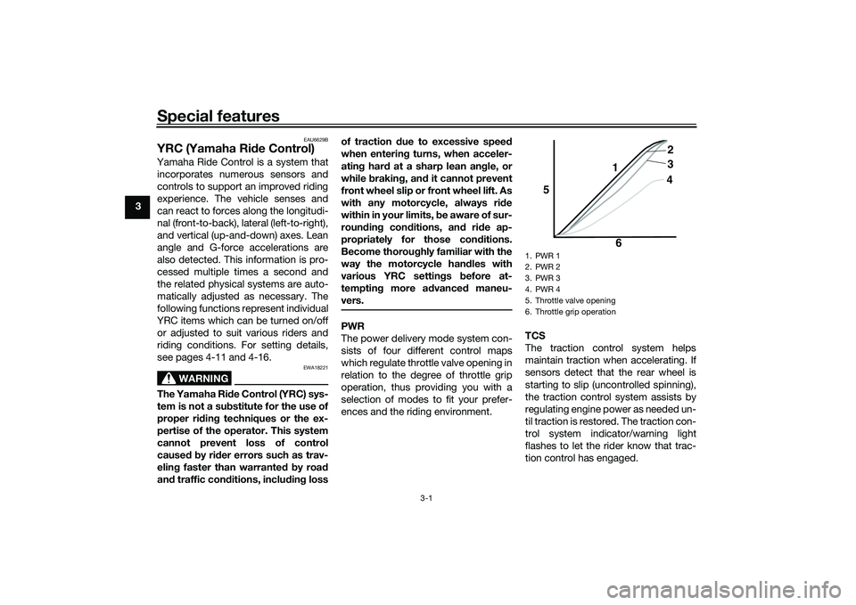
PWR
The power delivery mode system con-
sists of four different control maps
which regulate throttle valve opening in
relation to the degree of throttle grip
operation, thus providing you with a
selection of modes to fit your prefer-
ences and the riding environment. TCS
The traction control system helps
maintain traction when accelerating. If
sensors detect that the rear wheel is
starting to slip (uncontrolled spinning),
the traction control system assists by
regulating engine power as needed un-
til traction is restored. The traction con-
trol system indicator/warning light
flashes to let the rider know that trac-
tion control has engaged.
1. PWR 1
2. PWR 2
3. PWR 3
4. PWR 4
5. Throttle valve opening
6. Throttle grip operation
5
64
3 2
1
UB3LE0E0.book Page 1 Tuesday, July 23, 2019 12:05 PM
Page 19 of 136
Special features
3-2
3
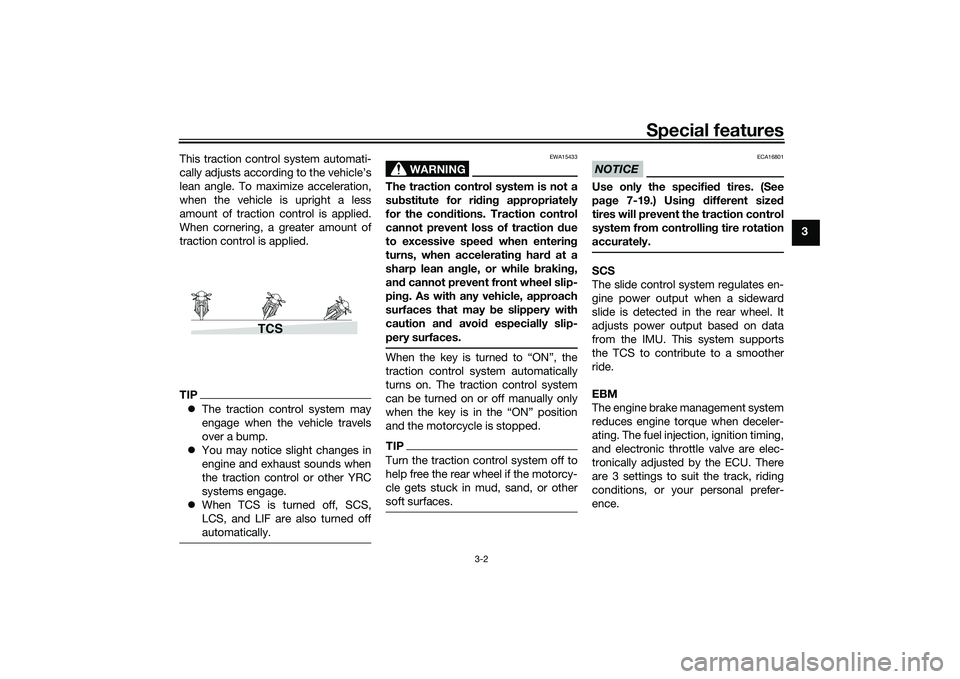
This traction control system automati-
cally adjusts according to the vehicle’s
lean angle. To maximize acceleration,
when the vehicle is upright a less
amount of traction control is applied.
When cornering, a greater amount of
traction control is applied.
TIP
The traction control system may
engage when the vehicle travels
over a bump.
You may notice slight changes in
engine and exhaust sounds when
the traction control or other YRC
systems engage.
When TCS is turned off, SCS,
LCS, and LIF are also turned off
automatically.
WARNING
EWA15433
The traction control system is not a
substitute for ri din g appropriately
for the con ditions. Traction control
cannot prevent loss of traction d ue
to excessive spee d when enterin g
turns, when acceleratin g har d at a
sharp lean an gle, or while brakin g,
an d cannot prevent front wheel slip-
pin g. As with any vehicle, approach
surfaces that may be slippery with
caution an d avoi d especially slip-
pery surfaces.When the key is turned to “ON”, the
traction control system automatically
turns on. The traction control system
can be turned on or off manually only
when the key is in the “ON” position
and the motorcycle is stopped.TIPTurn the traction control system off to
help free the rear wheel if the motorcy-
cle gets stuck in mud, sand, or other
soft surfaces.
NOTICE
ECA16801
Use only the specifie d tires. (See
pa ge 7-19.) Usin g different size d
tires will prevent the traction control
system from controllin g tire rotation
accurately.SCS
The slide control system regulates en-
gine power output when a sideward
slide is detected in the rear wheel. It
adjusts power output based on data
from the IMU. This system supports
the TCS to contribute to a smoother
ride.
EBM
The engine brake management system
reduces engine torque when deceler-
ating. The fuel injection, ignition timing,
and electronic throttle valve are elec-
tronically adjusted by the ECU. There
are 3 settings to suit the track, riding
conditions, or your personal prefer-
ence.
TCS
UB3LE0E0.book Page 2 Tuesday, July 23, 2019 12:05 PM
Page 25 of 136

Instrument and control functions
4-2
4
EAU10474
Main switch/steerin g lockThe main switch/steering lock controls
the ignition and lighting systems, and is
used to lock the steering. The various
positions are described below.TIPBe sure to use the standard key (black
bow) for regular use of the vehicle. To
minimize the risk of losing the code re-
registering key (red bow), keep it in a
safe place and only use it for code re-
registering.
EAU84031
ON
All electrical circuits are supplied with
power and the vehicle lights are turned
on. The engine can be started. The key
cannot be removed.TIP The headlight(s) will turn on when
the engine is started.
To prevent battery drain, do not
leave the key in the on position
without the engine running.
EAU10662
OFF
All electrical systems are off. The key
can be removed.
WARNING
EWA10062
Never turn the key to “OFF” or
“LOCK” while the vehicle is movin g.
Otherwise the electrical systems will
b e switched off, which may result in
loss of control or an acci dent.
EAU73800
LOCK
The steering is locked and all electrical
systems are off. The key can be re-
moved.
To lock the steering1. Turn the handlebars all the way to
the left.
2. With the key in the “OFF” position, push the key in and turn it to
“LOCK”.
3. Remove the key.
ON
OFF
LOCK
1. Push.
2. Turn.12
UB3LE0E0.book Page 2 Tuesday, July 23, 2019 12:05 PM
Page 28 of 136
Instrument and control functions
4-5
4 The LCS icon will flash and turn
white when the system has been
activated.
The traction control system can
only be turned off from the main
screen. Select TCS with the center
button, then push and hold the up
button until TCS OFF is displayed.
To turn the traction control system
back on, use the down button.
When TCS has been turned off,
the SCS, LCS, and LIF systems
are also turned off for all YRC
modes.
See “YRC Setting” on page 4-16
for more information on how to
customize YRC modes and adjust
YRC item setting levels.
EAU66100
Wheel switch “ ”
When the main screen is set to
STREET MODE, use the wheel switch
to scroll and reset the information dis-
play items.
When the main screen is set to TRACK
MODE, use the wheel switch to scroll
and reset the information display items
and to activate the lap timer. When the display has been changed to
the MENU screen, use the wheel
switch to navigate the setting modules
and make setting changes.
Operate the wheel switch as follows.
Rotate up
- rotate the wheel upward to
scroll up/left or increase a setting val-
ue.
Rotate down - rotate the wheel down-
ward to scroll down/right or decrease a
setting value.
Short push - briefly press the switch
inward to make and confirm selec-
tions.
Lon g push - press the switch inward
for one second to reset an information
display item or to access and exit the
MENU screen.
TIP See page 4-9 for more information
on the main screen and its func-
tions.
See page 4-15 for more informa-
tion on the MENU screen and how
to make setting changes.
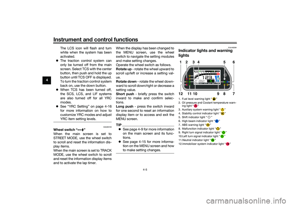
EAU4939H
Indicator li ghts an d warnin g
li g hts1. Fuel level warning light “ ”
2. Oil pressure and Coolant temperature warn-
ing light “ ”
3. Auxiliary system warning light “ ”
4. Stability control indicator light “ ”
5. Shift indicator light “ ”
6. High beam indicator light “ ”
7. ABS warning light “ ”
8. Malfunction indicator light “ ”
9. Right turn signal indicator light “ ”
10.Left turn signal indicator light “ ”
11.Neutral indicator light “ ”
12.Immobilizer system indicator light “ ”
ABS
1 2
GPSN
LCSQS
LIF 2
ODO123456 TRIP-1
1234.5
1000 r/min
km
km
km/h
10:
00
MODE-APWR 1TCS 3SCS 2EBM 1T-2
5
12
6
7
9
8
1012
11
3
4
UB3LE0E0.book Page 5 Tuesday, July 23, 2019 12:05 PM
Page 29 of 136

Instrument and control functions
4-6
4
EAU88280
Turn si gnal in dicator li ghts “ ”
an d“”
Each indicator light will flash when its
corresponding turn signal lights are
flashing.
EAU88300
Neutral in dicator li ght “ ”
This indicator light comes on when the
transmission is in the neutral position.
EAU88310
Hi gh beam in dicator li ght “ ”
This indicator light comes on when the
high beam of the headlight is switched
on.
EAU88320
Fuel level warnin g li ght “ ”
This warning light comes on when the
fuel level drops below approximately
3.0 L (0.79 US gal, 0.66 Imp.gal). When
this occurs, refuel as soon as possible.
The electrical circuit of the warning
light can be checked by turning the ve-
hicle on. The warning light should
come on for a few seconds, and then
go off.
TIPIf the warning light does not come on at
all, remains on after refueling, or if the
warning light flashes repeatedly, have
a Yamaha dealer check the vehicle.
EAU88330
Malfunction in dicator li ght
(MIL) “ ”
This light comes on or flashes if a prob-
lem is detected in the engine or other
vehicle control system. If this occurs,
have a Yamaha dealer check the on-
board diagnostic system. The electri-
cal circuit of the warning light can be
checked by vehicle power on. The light
should come on for a few seconds,
and then go off. If the light does not
come on initially when the vehicle pow-
er on, or if the light remains on, have a
Yamaha dealer check the vehicle.NOTICE
ECA26820
If the MIL starts flashin g, re duce en-
g ine spee d to prevent exhaust sys-
tem damag e.
TIPThe engine is sensitively controlled for
the on-board diagnostic system to de-
tect deterioration and malfunction of
the emission control system. Due to
this specification, the MIL may come
on or flash for vehicle modifications,
lack of maintenance, or excessive or
improper use of the motorcycle. To
prevent this, observe these precau-
tions.
Do not attempt to modify the soft-
ware of the engine control unit.
Do not add any electrical acces-
sories that interfere with engine
control.
Do not use aftermarket accesso-
ries or parts such as suspension,
spark plugs, injectors, exhaust
system, etc.
Do not change drivetrain specifi-
cations (chain, sprockets, wheels,
tires, etc.).
Do not remove or alter the O2 sen-
sor, air induction system, or ex-
haust parts (catalysts or EXUP,
etc.).
Maintain proper drive chain.
UB3LE0E0.book Page 6 Tuesday, July 23, 2019 12:05 PM
Page 30 of 136

Instrument and control functions
4-7
4
Maintain correct tire pressure.
Maintain proper brake pedal
height to prevent rear brake from
dragging.
Do not operate the vehicle in an
extreme manner. For example, re-
peated or excessive opening and
closing of the throttle, racing,
burnouts, wheelies, extended
half-clutch use, etc.
EAU88342
ABS warnin g li ght “ ”
In normal operation, the ABS warning
light comes on when the vehicle is
turned on, and goes off after traveling
at a speed of 10 km/h (6 mi/h) or high-
er.TIPIf the warning light does not work as
described above, or if the warning light
comes on while riding, the ABS may
not work correctly. Have a Yamaha
dealer check the vehicle as soon as
possible.
WARNING
EWA16043
If the ABS warnin g lig ht does not
turn off after reachin g 10 km/h (6
mi/h), or if the warnin g li ght comes
on while ri din g:
Use extra caution to avoi d pos-
si ble wheel lock durin g emer-
g ency brakin g.
Have a Yamaha dealer check
the vehicle as soon as possi ble.
EAU67433
Shift in dicator li ght “ ”
This indicator light comes on when it is
time to shift to the next higher gear.
The engine speeds at which it comes
on or goes off can be adjusted. (See
page 4-25.)TIPWhen the vehicle is turned on, this light
should come on for a few seconds and
then go off. If the light does not come
on, or if the light remains on, have a
Yamaha dealer check the vehicle.
EAU88350
Immo bilizer system in dicator
li g ht “ ”
When the main switch is turned off and
30 seconds have passed, the indicator
light will flash steadily to indicate the
immobilizer system is enabled. After 24
hours have passed, the indicator light
will stop flashing, however the immobi-
lizer system is still enabled.TIPWhen the vehicle is turned on, this light
should come on for a few seconds and
then go off. If the light does not come
on, or if the light remains on, have a
Yamaha dealer check the vehicle.Transpon der interference
If the immobilizer system indicator light
flashes in the pattern, slowly 5 times
then quickly 2 times, this could be
caused by transponder interference. If
this occurs, try the following. 1. Make sure there are no other im- mobilizer keys close to the main
switch.
2. Use the code re-registering key to start the engine.
UB3LE0E0.book Page 7 Tuesday, July 23, 2019 12:05 PM
Page 31 of 136

Instrument and control functions
4-8
4
3. If the engine starts, turn it off, and
try starting the engine with the
standard keys.
4. If one or both of the standard keys do not start the engine, take the
vehicle and all 3 keys to a Yamaha
dealer to have the standard keys
re-registered.
EAU88390
Sta bility control in dicator li ght “ ”
This indicator light comes on when the
TCS, SCS, or LIF systems have en-
gaged. It will also come on if the TCS is
set to “OFF” or if the TCS system be-
comes disabled while riding.TIPWhen the vehicle is turned on, this light
should come on for a few seconds and
then go off. If the light does not come
on, or if the light remains on, have a
Yamaha dealer check the vehicle.
EAU88362
Oil pressure an d Coolant tempera-
ture warnin g li ght “ ”
This warning light comes on if the en-
gine oil pressure is low or if the coolant
temperature is high. If this occurs, stop
the engine immediately.TIP When the vehicle is first turned on,
this light should come on until the
engine is started.
If a malfunction is detected, this
light will come on and the oil pres-
sure icon will flash.NOTICE
ECA22441
If the oil pressure an d coolant warn-
in g li ght does not g o off after start-
in g the en gine or if it comes on while
the en gine is runnin g, stop the vehi-
cle an d en gine imme diately.
If the en gine is overheatin g, the
coolant temperature warnin g
icon will come on. Let the en-
g ine cool. Check the coolant
level (see pa ge 7-40).
If the en gine oil pressure is low,
the oil pressure warnin g icon
will come on. Check the oil level
(see pa ge 7-14).
If the warnin g lig ht remains on
after lettin g the en gine cool an d
confirmin g the proper oil level,
have a Yamaha dealer check
the vehicle. Do not continue to
operate the vehicle!
EAU88370
Auxiliary system warnin g lig ht “ ”
This warning light comes on if a prob-
lem is detected in a non-engine-related
system.TIPWhen the vehicle is turned on, this light
should come on for a few seconds and
then go off. Otherwise, have a Yamaha
dealer check the vehicle.
UB3LE0E0.book Page 8 Tuesday, July 23, 2019 12:05 PM
Page 32 of 136

Instrument and control functions
4-9
4
EAU79285
DisplayThe display has two different main
screen display modes, STREET MODE
and TRACK MODE. Most of the func-
tions are viewable in either mode, but
the layout differs slightly. The following
items can be found on the display.
Speedometer
Tachometer
Information display
Transmission gear display
Front brake pressure indicator
Acceleration indicator
YRC setting display
MODE/PWR/TCS/SCS/EBM
YRC setting display
LCS/QS/LIF/BC
ERS indicator (YZF-R1M)
GPS indicator (CCU-equipped
models)
Logging indicator (CCU-equipped
models)
Clock
Revolution peak hold indicator
Lap timer
Various warning icons
Error mode warning “Err”
TIPThis model uses a thin-film-transistor
liquid-crystal display (TFT LCD) for
good contrast and readability in vari-
ous lighting conditions. However, due
to the nature of this technology, it is
normal for a small number of pixels to
be inactive.
STREET MODE1. YRC items LCS/QS/LIF/BC
2. Speedometer
3. GPS indicator (CCU-equipped models)
4. Logging indicator (CCU-equipped models)
5. Clock
6. Revolution peak hold indicator
7. Front brake pressure indicator
8. Acceleration indicator
9. Transmission gear display
10.ERS indicator (YZF-R1M)
11.YRC items MODE/PWR/TCS/SCS/EBM
12.Information display
13.Tachometer
1
2
GPS
N
LCS
QS
LIF 2
ODO
123456
TRIP-1
1234.5
1000 r/min
km
km
km/h
10:
00
MODE-
APWR
1
TCS
3
SCS
2
EBM
1
T-2
6
11 978
3
1
10
25
4
13
12
UB3LE0E0.book Page 9 Tuesday, July 23, 2019 12:05 PM
Page 58 of 136
Instrument and control functions
4-35
4
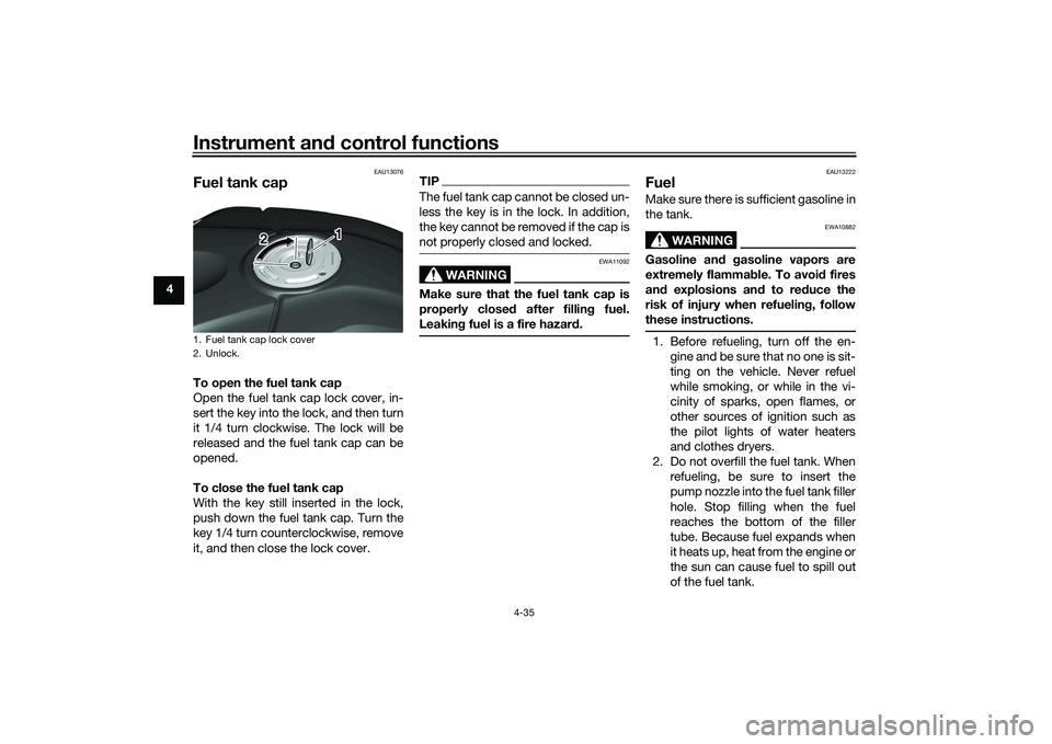
EAU13076
Fuel tank capTo open the fuel tank cap
Open the fuel tank cap lock cover, in-
sert the key into the lock, and then turn
it 1/4 turn clockwise. The lock will be
released and the fuel tank cap can be
opened.
To close the fuel tank cap
With the key still inserted in the lock,
push down the fuel tank cap. Turn the
key 1/4 turn counterclockwise, remove
it, and then close the lock cover.
TIPThe fuel tank cap cannot be closed un-
less the key is in the lock. In addition,
the key cannot be removed if the cap is
not properly closed and locked.
WARNING
EWA11092
Make sure that the fuel tank cap is
properly close d after fillin g fuel.
Leakin g fuel is a fire hazar d.
EAU13222
FuelMake sure there is sufficient gasoline in
the tank.
WARNING
EWA10882
Gasoline an d g asoline vapors are
extremely flamma ble. To avoi d fires
an d explosions an d to re duce the
risk of injury when refuelin g, follow
these instructions.1. Before refueling, turn off the en- gine and be sure that no one is sit-
ting on the vehicle. Never refuel
while smoking, or while in the vi-
cinity of sparks, open flames, or
other sources of ignition such as
the pilot lights of water heaters
and clothes dryers.
2. Do not overfill the fuel tank. When refueling, be sure to insert the
pump nozzle into the fuel tank filler
hole. Stop filling when the fuel
reaches the bottom of the filler
tube. Because fuel expands when
it heats up, heat from the engine or
the sun can cause fuel to spill out
of the fuel tank.
1. Fuel tank cap lock cover
2. Unlock.
1
2
UB3LE0E0.book Page 35 Tuesday, July 23, 2019 12:05 PM