YAMAHA YZF-R7 1999 Owners Manual
Manufacturer: YAMAHA, Model Year: 1999, Model line: YZF-R7, Model: YAMAHA YZF-R7 1999Pages: 381, PDF Size: 18.88 MB
Page 331 of 381

7 - 81
CHAS
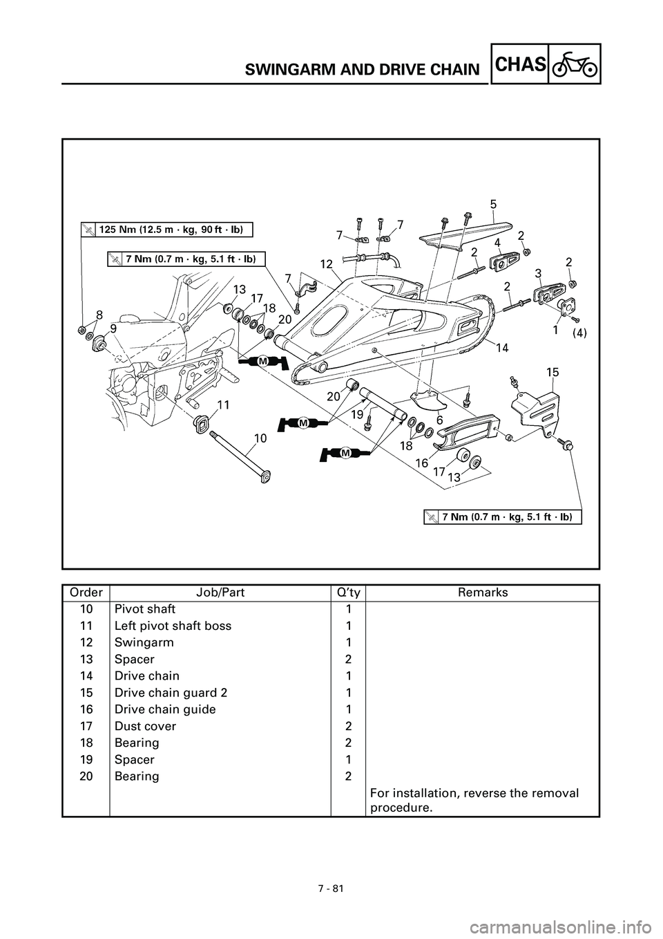
Order Job/Part Q’ty Remarks
10 Pivot shaft 1
11 Left pivot shaft boss 1
12 Swingarm 1
13 Spacer 2
14 Drive chain 1
15 Drive chain guard 2 1
16 Drive chain guide 1
17 Dust cover 2
18 Bearing 2
19 Spacer 1
20 Bearing 2
For installation, reverse the removal
procedure.
SWINGARM AND DRIVE CHAIN
Page 332 of 381

7 - 82
CHAS
EB707100
NOTE:
Before removing the drive sprocket,
drive chain, and rear wheel, measure the
drive chain slack and the length of a ten-
link section of the drive chain.
EB707111
REMOVING THE SWINGARM
1. Stand the motorcycle on a level surface.
WARNINGWARNING
Securely support the motorcycle so that
there is no danger of it falling over.
NOTE:
Place the motorcycle on a suitable stand
so that the rear wheel is elevated.
2. Measure:
• swingarm side play
• swingarm vertical movement
t t t t t t t t t t t t t t t t t t t t t t t t t t t
a. Measure the tightening torque of the
pivot shaft nut.
b. Measure the swingarm side play
by moving the swingarm from side to
side.
c. If the swingarm side play is out of
specification, check the spacers, bear-
ings, washers, and dust covers.
d. Check the swingarm vertical move-
ment
õ by moving the swingarm up
and down.
If swingarm vertical movement is not
smooth or if there is binding, check the
spacers, bearings, washers, and dust
covers.
s s s s s s s s s s s s s s s s s s s s s s s s s s s
T R..
Pivot shaft nut
125 Nm (12.5 m • kg, 90 ft • lb)
Swingarm side play (at the
end of the swingarm)
1.0 mm (0.04 in)
SWINGARM AND DRIVE CHAIN
Page 333 of 381

7 - 83
CHAS
EB707120
REMOVING THE DRIVE CHAIN
1. Remove:
• drive chain
(with the drive chain cutter)
NOTE:
Only cut the drive chain if it or the swin-
garm is to be replaced.
Drive chain cutter
90890-01286
EB707400
CHECKING THE SWINGARM
1. Check:
• swingarm
Bends/cracks/damage ® Replace.
NOTE:
If the swingarm must be replaced, the
drive chain must be cut with a drive
chain cutter.
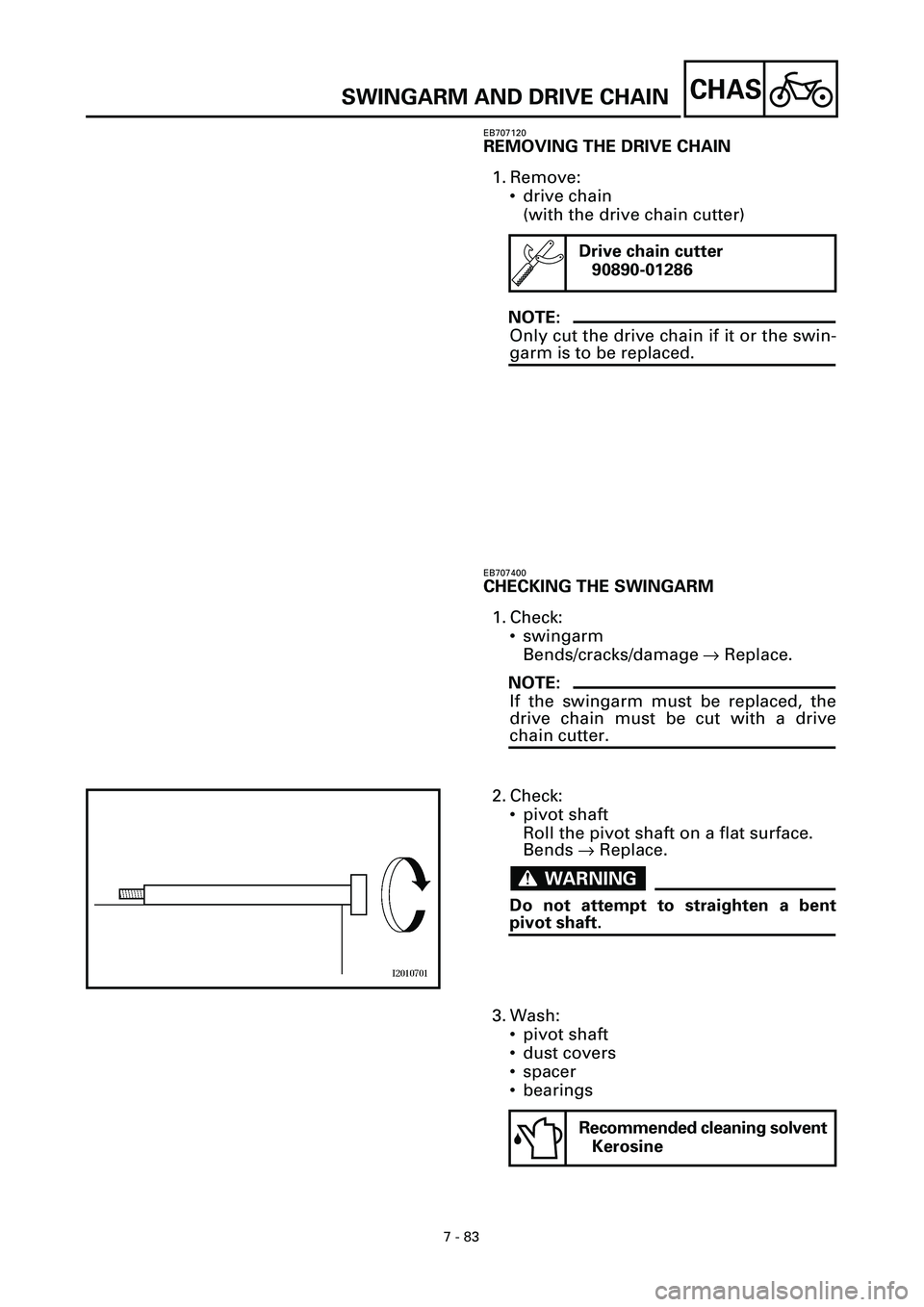
2. Check:
• pivot shaft
Roll the pivot shaft on a flat surface.
Bends ® Replace.
WARNINGWARNING
Do not attempt to straighten a bent
pivot shaft.
3. Wash:
• pivot shaft
• dust covers
• spacer
• bearings
Recommended cleaning solvent
Kerosine
SWINGARM AND DRIVE CHAIN
Page 334 of 381

7 - 84
CHAS
4. Check:
• dust covers
• spacer
• oil seals
Damage/wear ® Replace.
• bearings
Damage/pitting ® Replace.
EB707410
CHECKING THE DRIVE CHAIN
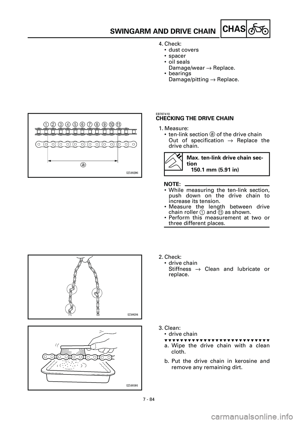
1. Measure:
• ten-link section a of the drive chain
Out of specification ® Replace the
drive chain.
NOTE:
• While measuring the ten-link section,
push down on the drive chain to
increase its tension.
• Measure the length between drive
chain roller 1 and A as shown.
• Perform this measurement at two or
three different places.
Max. ten-link drive chain sec-
tion
150.1 mm (5.91 in)
2. Check:
• drive chain
Stiffness ® Clean and lubricate or
replace.
3. Clean:
• drive chain
t t t t t t t t t t t t t t t t t t t t t t t t t t t
a. Wipe the drive chain with a clean
cloth.
b. Put the drive chain in kerosine and
remove any remaining dirt.
SWINGARM AND DRIVE CHAIN
Page 335 of 381

7 - 85
CHAS
c. Remove the drive chain from the ker-
osine and completely dry it.
ACHTUNG:CAUTION:
This motorcycle has a drive chain with
small rubber O-rings 1 between the
drive chain side plates. Never use high-
pressure water or air, steam, gasoline,
certain solvents (e.g., benzine), or a
coarse brush to clean the drive chain.
High-pressure methods could force dirt
or water into the drive chain’s internals,
and solvents will deteriorate the O-
rings. A coarse brush can also damage
the O-rings. Therefore, use only kero-
sine to clean the drive chain.
s s s s s s s s s s s s s s s s s s s s s s s s s s s
4. Check:
• O-rings 1
Damage ® Replace the drive chain.
• drive chain rollers 2
Damage/wear ® Replace the drive
chain.
• drive chain side plates 3
Cracks/damage/wear ® Replace the
drive chain.
5. Lubricate:
• drive chain
Recommended lubricant
Engine oil or chain lubricant
suitable for O-ring chains
6. Check:
• drive sprocket
• rear wheel sprocket
More than 1/4 tooth a wear ® Replace
the drive chain sprockets as a set.
Bent teeth ® Replace the drive chain
sprockets as a set.
b Correct
1Drive chain roller
2Drive chain sprocket
SWINGARM AND DRIVE CHAIN
Page 336 of 381

7 - 86
CHAS
EB707700
INSTALLING THE SWINGARM
1. Lubricate:
• bearings
• spacers
• dust covers
• pivot shaft
2. Install:
• spacers
• swingarm
• pivot shaft bosses
• pivot shaft
• washer
• pivot shaft nut
3. Install:
• drive chain pullers
NOTE:
Install the drive chain pullers onto the
swingarm so that the sides stamped
“IN” face toward the inside (i.e., the rear
wheel).
4. Install:
• rear shock absorber assembly
• rear wheel
Refer to “REAR SHOCK ABSORBER
ASSEMBLY” and “REAR WHEEL”.
5. Adjust:
• drive chain slack
Refer to “ADJUSTING THE DRIVE
CHAIN SLACK” in chapter 3.
Recommended lubricant
Molybdenum disulfide grease
Drive chain slack
40 ~ 50 mm (1.57 ~ 1.97 in)
T R..125 Nm (12.5 m · kg, 90 ft · lb)
SWINGARM AND DRIVE CHAIN
Page 337 of 381

8 - 1
–+ELEC
ELECTRICAL COMPONENTS
EB800000
ELECTRICAL
ELECTRICAL COMPONENTS
1
Wire harness
2
Main switch
3
Front brake light switch
4
Ignition coils
5
Clutch switch
6
Throttle position sensor
7
Intake air temperature sensor
8
Intake air pressure sensor
9
Atmospheric pressure sensor
0
Turn signal relay
A
Relay unit
B
ECU
C
CDI unit
D
Fuse box
E
Fall detection switch
F
Starter relay
G
Main fuse
H
Main relay
I
Battery
J
Rectifier/regulator
K
Rear brake light switch
L
Neutral switch
M
Speed sensor
N
Sidestand switch
O
Stator coil assembly
P
Oil level switch
Q
Pickup coil
R
Radiator fan
S
Horn
T
Coolant temperature
sender
U
Thermo switch
V
Camshaft sensor
8
Page 338 of 381

8 - 2
–+ELEC
SWITCHES
EB801000
SWITCHES
CHECKING SWITCH CONTINUITY
Check each switch for continuity with the
pocket tester. If the continuity reading is
incorrect, check the wiring connections and
if necessary, replace the switch.
CAUTION:
Never insert the tester probes into the cou-
pler terminal slots
1
. Always insert the
probes from the opposite end of the cou-
pler, taking care not to loosen or damage
the leads.
NOTE:
• Before checking for continuity, set the
pocket tester to “0” and to the “
W
´
1”
range.
• When checking for continuity, switch back
and forth between the switch positions a
few times.
The terminal connections for switches (e.g.,
main switch, engine stop switch) are shown
in an illustration similar to the one on the
left.
The switch positions
a
are shown in the far
left column and the switch lead colors
b
are shown in the top row in the switch illus-
tration.
NOTE:
“ ” indicates a continuity of electric-
ity between switch terminals (i.e., a closed
circuit at the respective switch position).
The example illustration on the left shows
that:
There is continuity between blue/red and
red when the switch is set to “ ”.
There is continuity between blue/red and
blue, between brown/blue and red, and
between blue/yellow and blue/black when
the switch is set to “ON”.
Pocket tester
90890-03112
ONR
Br/LL/YL/B
OFF
ab
Br/L
L/B R
L/Y
8
Page 339 of 381

8 - 3
–+ELEC
CHECKING THE SWITCHES
EB801010
CHECKING THE SWITCHES
Check each switch for damage or wear, proper connections, and also for continuity between
the terminals. Refer to “CHECKING SWITCH CONTINUITY”.
Damage/wear
® Repair or replace the switch.
Improperly connected ® Properly connect.
Incorrect continuity reading ® Replace the switch.
1Main switch
2Light switch
3Pass switch
4Dimmer switch
5Turn signal switch6Horn switch
7Clutch switch
8Engine stop switch
9Start switch
0Front brake light switchAOil level switch
BRear brake light switch
CFuse
DNeutral switch
ESidestand switch
1L/YL/B
LL/R
R
Br/L
OFF
ONP
L/RLBr/LRL/YL/B
3
4
5
Br/WR/YPLB
Dg Y
G Ch
B/YL/YPASS—
R/YY
67
YG
—BP
(BLUE)
(BLACK)
(BLACK)
R/WBr
R/BB
G/YL/W
B
B
G/YBr
OFF
ChBr/WDg
8R/WR/B
9
0—L/WB
2R/YL•
C
E
(BLUE)
B
B
B D
(BROWN)
Sb
A
W
L/YB/Y
L/YB/Y
Page 340 of 381

8 - 4
–+ELECCHECKING THE BULBS AND BULB SOCKETS
EB801020
CHECKING THE BULBS AND
BULB SOCKETS
Check each bulb and bulb socket for dam-
age or wear, proper connections, and also
for continuity between the terminals.
Damage/wear ® Repair or replace the
bulb, bulb socket or both.
Improperly connected ® Properly con-
nect.
Incorrect continuity reading ® Repair or
replace the bulb, bulb socket or both.
TYPES OF BULBS
The bulbs used on this motorcycle are
shown in the illustration on the left.
• Bulbs A and B are used for headlights
and usually use a bulb holder which must
be detached before removing the bulb.
The majority of these bulbs can be
removed from their respective socket by
turning them counterclockwise.
• Bulb C is used for turn signal and tail/
brake lights and can be removed from the
socket by pushing and turning the bulb
counterclockwise.
• Bulbs
D and E are used for meter and
indicator lights and can be removed from
their respective socket by carefully pulling
them out.
CHECKING THE CONDITION OF THE BULBS
The following procedure applies to all of
the bulbs.
1.Remove:
• bulb