door lock Abarth 500 2020 Owner handbook (in English)
[x] Cancel search | Manufacturer: ABARTH, Model Year: 2020, Model line: 500, Model: Abarth 500 2020Pages: 196, PDF Size: 3.53 MB
Page 13 of 196
KEYS
1)
1)
MECHANICAL KEY
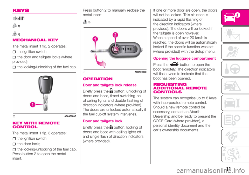
The metal insert 1 fig. 2 operates:
the ignition switch;
the door and tailgate locks (where
provided);
the locking/unlocking of the fuel cap.
KEY WITH REMOTE
CONTROL
The metal insert 1 fig. 3 operates:
the ignition switch;
the door lock;
the locking/unlocking of the fuel cap.
Press button 2 to open the metal
insert.Press button 2 to manually reclose the
metal insert.
2)
OPERATION
Door and tailgate lock release
Briefly press thebutton: unlocking of
doors and boot, timed switching-on
of ceiling lights and double flashing of
direction indicators (where provided).
The doors are unlocked automatically if
the fuel cut-off system intervenes.
Door and tailgate lock
Briefly press thebutton: locking of
doors and boot with ceiling lights off
and single flash of direction indicators
(where provided).If one or more door are open, the doors
will not be locked. This situation is
indicated by a rapid flashing of
the direction indicators (where
provided). The doors will be locked if
the tailgate is open however.
When a speed of over 20 km/h is
reached, the doors will be automatically
locked if the specific function was set
(where provided) with the Setup menu.
Opening the luggage compartment
Press thebutton to open the
boot remotely. The direction indicators
will flash twice to indicate that the
boot has been opened.
REQUESTING
ADDITIONAL REMOTE
CONTROLS
The system can recognise up to 8 keys
with incorporated remote control.
Should a new remote control be
necessary, contact an Abarth
Dealership and be ready to present the
CODE Card (where provided), a
personal identity document and the
car's ownership documents.
2AB0A0303C
3AB0A0006C
11
Page 14 of 196
WARNING
1)The electronic components inside the
key may be damaged if the key is
subjected to strong shocks. In order to
ensure complete efficiency of the
electronic devices inside the keys, they
should never be exposed to direct sunlight.
2)Press button 2 fig. 3only with the key
away from your body, especially your eyes
and from objects which could get
damaged (e.g. your clothes). Do not leave
the key unattended to avoid the button
being accidentally pressed while it is being
handled, e.g. by a child.
WARNING
1)Used batteries may be harmful to the
environment if not disposed of correctly.
They must be disposed of as specified by
law in the special containers or taken to
an Abarth Dealership, which will take care
of their disposal.
IGNITION DEVICE
OPERATION
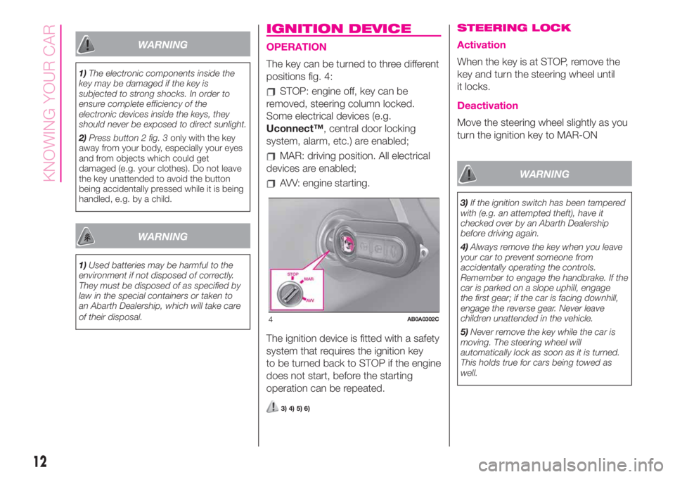
The key can be turned to three different
positions fig. 4:
STOP: engine off, key can be
removed, steering column locked.
Some electrical devices (e.g.
Uconnect™, central door locking
system, alarm, etc.) are enabled;
MAR: driving position. All electrical
devices are enabled;
AVV: engine starting.
The ignition device is fitted with a safety
system that requires the ignition key
to be turned back to STOP if the engine
does not start, before the starting
operation can be repeated.
3) 4) 5) 6)
STEERING LOCK
Activation
When the key is at STOP, remove the
key and turn the steering wheel until
it locks.
Deactivation
Move the steering wheel slightly as you
turn the ignition key to MAR-ON
WARNING
3)If the ignition switch has been tampered
with (e.g. an attempted theft), have it
checked over by an Abarth Dealership
before driving again.
4)Always remove the key when you leave
your car to prevent someone from
accidentally operating the controls.
Remember to engage the handbrake. If the
car is parked on a slope uphill, engage
the first gear; if the car is facing downhill,
engage the reverse gear. Never leave
children unattended in the vehicle.
5)Never remove the key while the car is
moving. The steering wheel will
automatically lock as soon as it is turned.
This holds true for cars being towed as
well.
4AB0A0302C
12
KNOWING YOUR CAR
Page 16 of 196
DOORS
7)
1)
DOOR CENTRAL
LOCKING/UNLOCKING
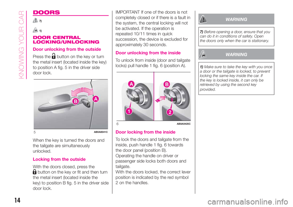
Door unlocking from the outside
Press thebutton on the key or turn
the metal insert (located inside the key)
to position A fig. 5 in the driver side
door lock.
When the key is turned the doors and
the tailgate are simultaneously
unlocked.
Locking from the outside
With the doors closed, press the
button on the key or fit and then turn
the metal insert (located inside the
key) to position B fig. 5 in the driver side
door lock.IMPORTANT If one of the doors is not
completely closed or if there is a fault in
the system, the central locking will not
be activated. If the operation is
repeated 10/11 times in quick
succession, the device is excluded for
approximately 30 seconds.
Door unlocking from the inside
To unlock from inside (door and tailgate
locks) pull handle 1 fig. 6 (position A).
Door locking from the inside
To lock the doors and tailgate from the
inside, push handle 1 fig. 6 towards
the door panel (position B).
Operating the handle on driver or
passenger side locks both doors and
tailgate.
With the doors locked, the correct lever
position is indicated by the red symbol
2 on the handles.
WARNING
7)Before opening a door, ensure that you
can do it in conditions of safety. Open
the doors only when the car is stationary.
WARNING
1)Make sure to take the key with you once
a door or the tailgate is locked, to prevent
locking the same key inside the car. If
the key is locked inside, it can only be
retrieved by using the second key
provided.
5AB0A0041C
6AB0A0425C
14
KNOWING YOUR CAR
Page 19 of 196
REAR SEATS
Extending the luggage
compartment
11)
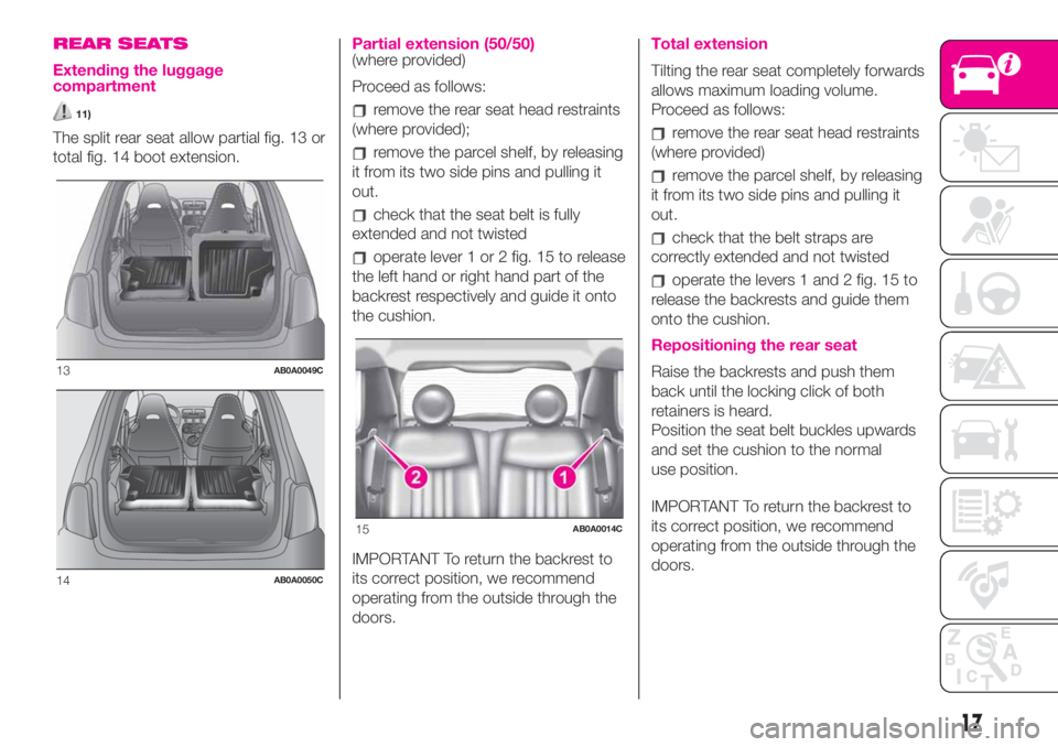
The split rear seat allow partial fig. 13 or
total fig. 14 boot extension.
Partial extension (50/50)(where provided)
Proceed as follows:
remove the rear seat head restraints
(where provided);
remove the parcel shelf, by releasing
it from its two side pins and pulling it
out.
check that the seat belt is fully
extended and not twisted
operate lever 1 or 2 fig. 15 to release
the left hand or right hand part of the
backrest respectively and guide it onto
the cushion.
IMPORTANT To return the backrest to
its correct position, we recommend
operating from the outside through the
doors.
Total extension
Tilting the rear seat completely forwards
allows maximum loading volume.
Proceed as follows:
remove the rear seat head restraints
(where provided)
remove the parcel shelf, by releasing
it from its two side pins and pulling it
out.
check that the belt straps are
correctly extended and not twisted
operate the levers 1 and 2 fig. 15 to
release the backrests and guide them
onto the cushion.
Repositioning the rear seat
Raise the backrests and push them
back until the locking click of both
retainers is heard.
Position the seat belt buckles upwards
and set the cushion to the normal
use position.
IMPORTANT To return the backrest to
its correct position, we recommend
operating from the outside through the
doors.13AB0A0049C
14AB0A0050C
15AB0A0014C
17
Page 25 of 196
WARNING
16)The daytime running lights are an
alternative to the dipped beam headlights
for driving during the daytime in countries
where it is compulsory to have lights on
during the day; where it is not compulsory,
the use of daytime running lights is
permitted.
17)Daytime running lights cannot replace
dipped beam headlights when driving at
night or through tunnels. The use of
daytime running lights is governed by the
highway code of the country in which
you are driving. Comply with legal
requirements.
ROOF LIGHTS
FRONT CEILING LIGHT
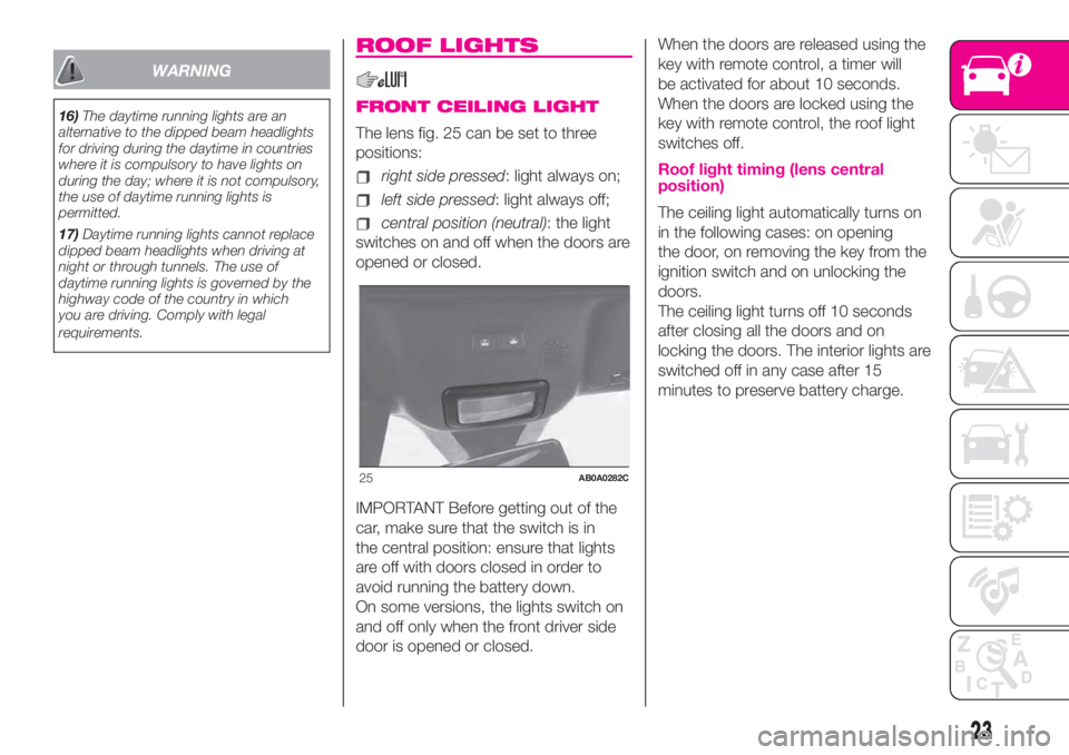
The lens fig. 25 can be set to three
positions:
right side pressed: light always on;
left side pressed: light always off;
central position (neutral): the light
switches on and off when the doors are
opened or closed.
IMPORTANT Before getting out of the
car, make sure that the switch is in
the central position: ensure that lights
are off with doors closed in order to
avoid running the battery down.
On some versions, the lights switch on
and off only when the front driver side
door is opened or closed.When the doors are released using the
key with remote control, a timer will
be activated for about 10 seconds.
When the doors are locked using the
key with remote control, the roof light
switches off.
Roof light timing (lens central
position)
The ceiling light automatically turns on
in the following cases: on opening
the door, on removing the key from the
ignition switch and on unlocking the
doors.
The ceiling light turns off 10 seconds
after closing all the doors and on
locking the doors. The interior lights are
switched off in any case after 15
minutes to preserve battery charge.
25AB0A0282C
23
Page 46 of 196
NOTE Buttons+and–activate different
functions according to the following
situations:
within the menu, they allow you to
scroll up or down through the options;
during setting operations, they
increase or decrease values.
The menu comprises the following
functions:
LIGHTING: adjusts the dashboard
and instrument panel lighting
SPEED BEEP: sets the vehicle
speed limit (km/h or mph). The driver is
alerted when this speed is exceeded.
TRIP B ACTIVATION/DATA: activates
(”On”) and deactivates (”Off”) the Trip
B display (partial trip counter)
SET TIME: set the display clock
SET DATE: sets the display date
AUTOCLOSE: enables or disables
automatic door locking on exceeding a
speed of 20 km/h
MEASUREMENT UNITS: sets the
measurement units for distance and
fuel consumption
LANGUAGE: sets the display
language
WARNING VOLUME: sets the
volume (on 8 levels) of the audible
warning (buzzer) that accompanies the
failure/warning display
SEAT BELT BUZZER: reactivation of
the SBR buzzer (displayed only if the
SBR system was disabled by the
Abarth Dealership)
SERVICE: displays mileage intervals
for scheduled servicing
AIRBAG/PASSENGER BAG:
enables/disables the passenger side
airbag
DAYTIME RUNNING LIGHTS:
enables/disables daytime running lights
ITPMS RESET: resets the iTPMS
system (”self-learning”, see the “iTPMS
System” paragraph)
SEE RADIO (if present): enables/
disables duplicating some of the radio
information shown on theUconnect™
system display on the instrument panel
display.
SEE PHONE (if present): enables/
disables duplicating some of the call
information shown on theUconnect™
system display on the instrument panel
display.
SEE NAVIGATION (if present):
enables/disables duplicating some of
the navigation information shown on
theUconnect™system display on the
instrument panel display.
EXIT MENU
TRIP COMPUTER
The Trip computer is used to display
information on car operation when the
key is turned to MAR.
This function is characterised by two
separate memories, called "Trip A" and
"Trip B", where the car's "complete
missions" (journeys) are recorded in a
reciprocally independent manner, as
well as, for versions where present,
"Instant info" and "Best average
consumption".
Both memories can be reset: i.e. start
of a new journey.
"Trip A" can be used to display the
values relating to:
Range (where present)
Distance travelled A
Average consumption A
Instantaneous fuel consumption
(where present)
Average speed A
Trip time A (driving time)
Reset Trip A.
“Best average consumption": in ECO
mode, displays a screen summarising
the best average consumption (where
provided). The
icon indicates the
best performance. This information can
be reset by resetting Trip A.
"Trip B" allows the display of the
following parameters:
44
KNOWING THE INSTRUMENT PANEL
Page 102 of 196
REPLACING AN
EXTERIOR BULB
For the type of bulb and power rating,
see paragraph "Replacing a bulb".
FRONT LIGHT CLUSTERS
The front light clusters contain side
lights, dipped headlights, main beam
headlights and direction indicator bulbs.
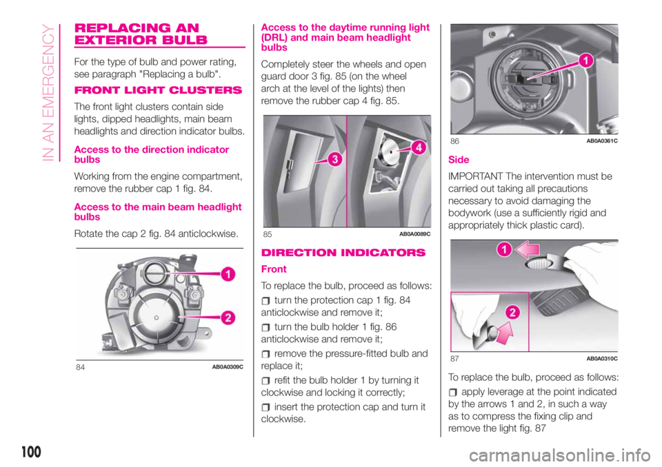
Access to the direction indicator
bulbs
Working from the engine compartment,
remove the rubber cap 1 fig. 84.
Access to the main beam headlight
bulbs
Rotate the cap 2 fig. 84 anticlockwise.
Access to the daytime running light
(DRL) and main beam headlight
bulbs
Completely steer the wheels and open
guard door 3 fig. 85 (on the wheel
arch at the level of the lights) then
remove the rubber cap 4 fig. 85.
DIRECTION INDICATORS
Front
To replace the bulb, proceed as follows:
turn the protection cap 1 fig. 84
anticlockwise and remove it;
turn the bulb holder 1 fig. 86
anticlockwise and remove it;
remove the pressure-fitted bulb and
replace it;
refit the bulb holder 1 by turning it
clockwise and locking it correctly;
insert the protection cap and turn it
clockwise.
Side
IMPORTANT The intervention must be
carried out taking all precautions
necessary to avoid damaging the
bodywork (use a sufficiently rigid and
appropriately thick plastic card).
To replace the bulb, proceed as follows:
apply leverage at the point indicated
by the arrows 1 and 2, in such a way
as to compress the fixing clip and
remove the light fig. 87
84AB0A0309C
85AB0A0089C
86AB0A0361C
87AB0A0310C
100
IN AN EMERGENCY
Page 105 of 196
REPLACING FUSES
GENERAL INFORMATION
Fuses protect the electrical system:
they intervene (blow) in the event of a
failure or improper action on the
system.
121) 122) 123) 124) 125) 126)
To facilitate fuse replacement, use the
pliers hooked inside the fuse box lid on
the dashboard left-hand side.
Refer to the tables on the following
pages to identify the protective fuse.
FUSE LOCATION
Dashboard fuse box
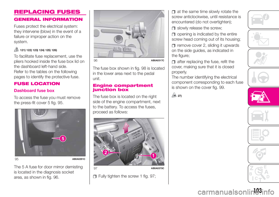
To access the fuse you must remove
the press-fit cover 5 fig. 95.
The 5 A fuse for door mirror demisting
is located in the diagnosis socket
area, as shown in fig. 96.The fuse box shown in fig. 98 is located
in the lower area next to the pedal
unit.
Engine compartment
junction box
The fuse box is located on the right
side of the engine compartment, next
to the battery. To access the fuses,
proceed as follows:
Fully tighten the screw 1 fig. 97;
at the same time slowly rotate the
screw anticlockwise, until resistance is
encountered (do not overtighten);
slowly release the screw;
opening is indicated by the entire
screw head coming out of its housing;
remove cover 2, sliding it upwards
on the side guides, as indicated in
the figure;
after replacing the fuse, refit the
cover, making sure that it is closed
properly.
The number identifying the electrical
component corresponding to each fuse
is shown on the cover fig. 99.
27)
95AB0A0291C
96AB0A0317C
97AB0A0375C
103
Page 106 of 196
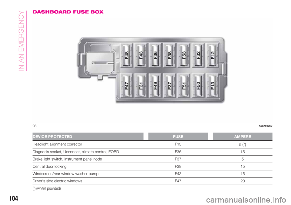
DASHBOARD FUSE BOX
DEVICE PROTECTED FUSE AMPERE
Headlight alignment corrector F13
5(*)
Diagnosis socket, Uconnect, climate control, EOBD F36 15
Brake light switch, instrument panel node F37 5
Central door locking F38 15
Windscreen/rear window washer pump F43 15
Driver's side electric windows F47 20
(*) (where provided)
98AB0A0106C
104
IN AN EMERGENCY
Page 113 of 196

WARNING
29)Never use a fast battery-charger to
start the engine as this could damage the
electronic systems of your vehicle,
particularly the ignition and engine fuel
supply control units.
WARNING
129)This starting procedure must be
performed by expert personnel because
incorrect actions could cause electrical
discharge of considerable intensity.
Furthermore, battery fluid is poisonous and
corrosive: avoid contact with skin and
eyes. Keep naked flames and lighted
cigarettes away from the battery and do
not cause sparks.
FUEL CUT-OFF
SYSTEM
This intervenes in the case of an impact
causing:
the interruption of the fuel supply
with the engine consequently cutting
out
the automatic unlocking of the doors
turning on the lights inside the car.
The intervention of the system is
indicated by a message shown on the
display.
IMPORTANT Carefully check the car for
fuel leaks, for instance in the engine
compartment, under the car or near the
tank area.
130)
After a crash, turn the ignition key to
STOP position to prevent the battery
from running down.
To restore the correct operation of the
car, proceed as follows:
turn the ignition key to the MAR
position
activate the right direction indicator
deactivate the right direction
indicator
activate the left direction indicator
deactivate the left direction indicator
activate the right direction indicator
deactivate the right direction
indicator
activate the left direction indicator
deactivate the left direction indicator
turn the ignition key to the STOP
position
turn the ignition key to the MAR-ON
position.
WARNING
130)If, after an impact, you smell fuel or
notice leaks from the fuel system, do
not reactivate the system to avoid the risk
of fire.
111