fuse Abarth 500 2020 Owner handbook (in English)
[x] Cancel search | Manufacturer: ABARTH, Model Year: 2020, Model line: 500, Model: Abarth 500 2020Pages: 196, PDF Size: 3.53 MB
Page 30 of 196
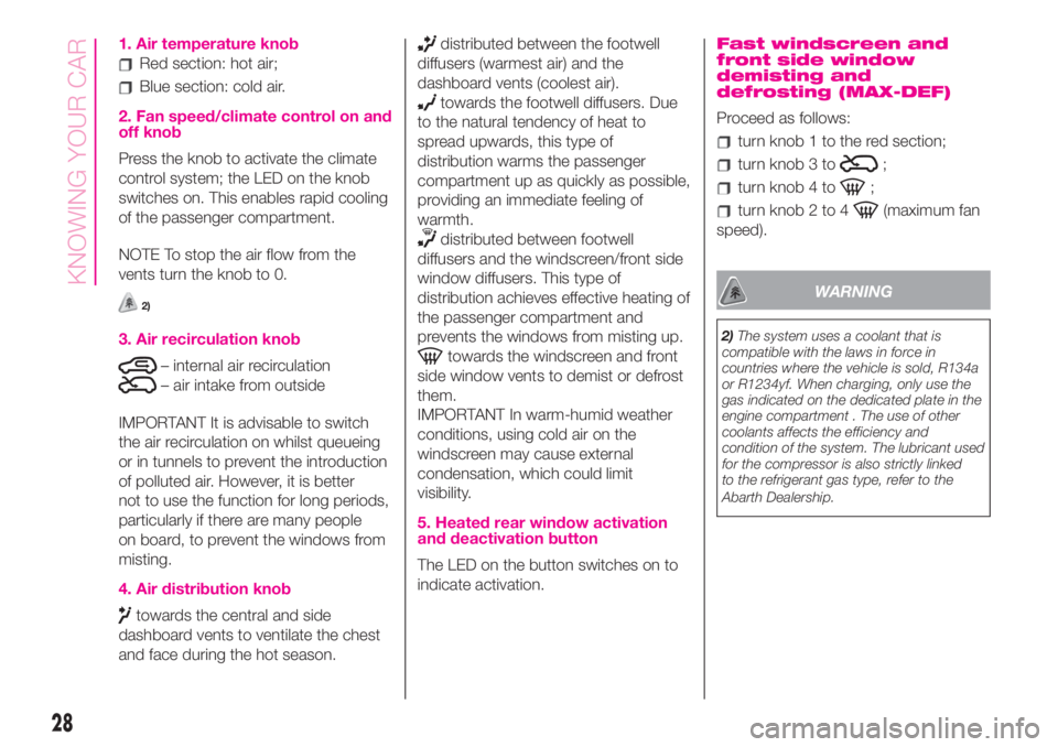
1. Air temperature knob
Red section: hot air;
Blue section: cold air.
2. Fan speed/climate control on and
off knob
Press the knob to activate the climate
control system; the LED on the knob
switches on. This enables rapid cooling
of the passenger compartment.
NOTE To stop the air flow from the
vents turn the knob to 0.
2)
3. Air recirculation knob
– internal air recirculation
– air intake from outside
IMPORTANT It is advisable to switch
the air recirculation on whilst queueing
or in tunnels to prevent the introduction
of polluted air. However, it is better
not to use the function for long periods,
particularly if there are many people
on board, to prevent the windows from
misting.
4. Air distribution knob
towards the central and side
dashboard vents to ventilate the chest
and face during the hot season.
distributed between the footwell
diffusers (warmest air) and the
dashboard vents (coolest air).
towards the footwell diffusers. Due
to the natural tendency of heat to
spread upwards, this type of
distribution warms the passenger
compartment up as quickly as possible,
providing an immediate feeling of
warmth.
distributed between footwell
diffusers and the windscreen/front side
window diffusers. This type of
distribution achieves effective heating of
the passenger compartment and
prevents the windows from misting up.
towards the windscreen and front
side window vents to demist or defrost
them.
IMPORTANT In warm-humid weather
conditions, using cold air on the
windscreen may cause external
condensation, which could limit
visibility.
5. Heated rear window activation
and deactivation button
The LED on the button switches on to
indicate activation.
Fast windscreen and
front side window
demisting and
defrosting (MAX-DEF)
Proceed as follows:
turn knob 1 to the red section;
turn knob 3 to;
turn knob 4 to;
turn knob 2 to 4(maximum fan
speed).
WARNING
2)The system uses a coolant that is
compatible with the laws in force in
countries where the vehicle is sold, R134a
or R1234yf. When charging, only use the
gas indicated on the dedicated plate in the
engine compartment . The use of other
coolants affects the efficiency and
condition of the system. The lubricant used
for the compressor is also strictly linked
to the refrigerant gas type, refer to the
Abarth Dealership.
28
KNOWING YOUR CAR
Page 34 of 196
Opening and closing the roof
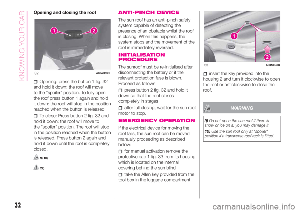
Opening: press the button 1 fig. 32
and hold it down: the roof will move
to the "spoiler" position. To fully open
the roof press button 1 again and hold
it down: the roof will stop in the position
reached when the button is released.
To close: Press button 2 fig. 32 and
hold it down: the roof will move to
the "spoiler" position. The roof will stop
in the position reached when the button
is released. Press button 2 again and
hold it down until the roof is completely
closed.
9) 10)
22)
ANTI-PINCH DEVICE
The sun roof has an anti-pinch safety
system capable of detecting the
presence of an obstacle whilst the roof
is closing. When this happens, the
system stops and the movement of the
roof is immediately reversed.
INITIALISATION
PROCEDURE
The sunroof must be re-initialised after
disconnecting the battery or if the
relevant protection fuse is blown.
Proceed as follows:
press button 2 fig. 32 and hold it
down so that the roof closes
completely in stages
after full closing, wait for the sun roof
motor to stop.
EMERGENCY OPERATION
If the electrical device for moving the
roof fails, the sun roof can be moved
manually proceeding as described
below:
for manual activation remove the
protective cap 1 fig. 33 from its housing
which is located on the internal
covering behind the sun blind
take the Allen key provided from the
tool box in the luggage compartment
insert the key provided into the
housing 2 and turn it clockwise to open
the roof or anticlockwise to close the
roof.
WARNING
9)Do not open the sun roof if there is
snow or ice on it: you may damage it
10)Use the sun roof only at "spoiler"
position if a transverse roof rack is fitted.
32AB0A0287C
33AB0A0040C
32
KNOWING YOUR CAR
Page 37 of 196
EMERGENCY OPERATION
If the buttons fail, the soft top can be
moved manually proceeding as
described below:
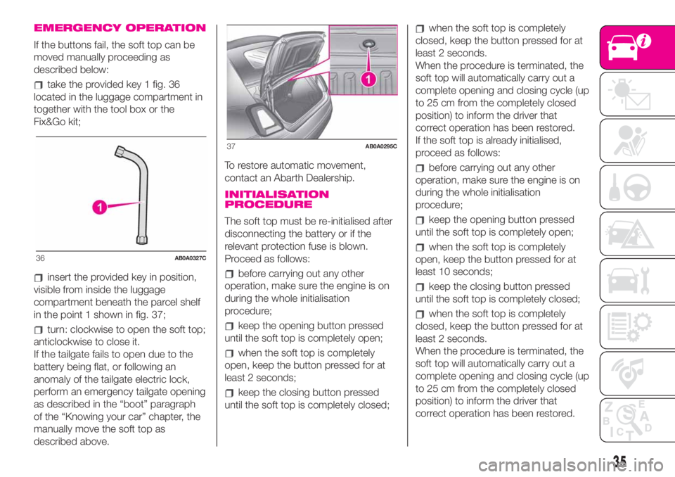
take the provided key 1 fig. 36
located in the luggage compartment in
together with the tool box or the
Fix&Go kit;
insert the provided key in position,
visible from inside the luggage
compartment beneath the parcel shelf
in the point 1 shown in fig. 37;
turn: clockwise to open the soft top;
anticlockwise to close it.
If the tailgate fails to open due to the
battery being flat, or following an
anomaly of the tailgate electric lock,
perform an emergency tailgate opening
as described in the “boot” paragraph
of the “Knowing your car” chapter, the
manually move the soft top as
described above.To restore automatic movement,
contact an Abarth Dealership.
INITIALISATION
PROCEDURE
The soft top must be re-initialised after
disconnecting the battery or if the
relevant protection fuse is blown.
Proceed as follows:
before carrying out any other
operation, make sure the engine is on
during the whole initialisation
procedure;
keep the opening button pressed
until the soft top is completely open;
when the soft top is completely
open, keep the button pressed for at
least 2 seconds;
keep the closing button pressed
until the soft top is completely closed;
when the soft top is completely
closed, keep the button pressed for at
least 2 seconds.
When the procedure is terminated, the
soft top will automatically carry out a
complete opening and closing cycle (up
to 25 cm from the completely closed
position) to inform the driver that
correct operation has been restored.
If the soft top is already initialised,
proceed as follows:
before carrying out any other
operation, make sure the engine is on
during the whole initialisation
procedure;
keep the opening button pressed
until the soft top is completely open;
when the soft top is completely
open, keep the button pressed for at
least 10 seconds;
keep the closing button pressed
until the soft top is completely closed;
when the soft top is completely
closed, keep the button pressed for at
least 2 seconds.
When the procedure is terminated, the
soft top will automatically carry out a
complete opening and closing cycle (up
to 25 cm from the completely closed
position) to inform the driver that
correct operation has been restored.
36AB0A0327C
37AB0A0295C
35
Page 59 of 196
Symbol What it means
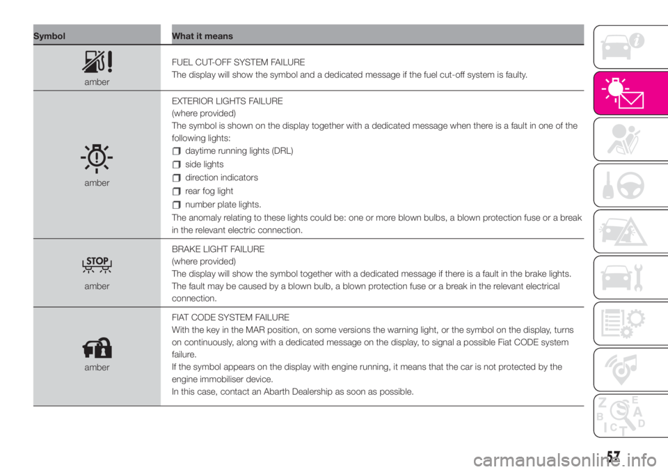
amberFUEL CUT-OFF SYSTEM FAILURE
The display will show the symbol and a dedicated message if the fuel cut-off system is faulty.
amberEXTERIOR LIGHTS FAILURE
(where provided)
The symbol is shown on the display together with a dedicated message when there is a fault in one of the
following lights:
daytime running lights (DRL)
side lights
direction indicators
rear fog light
number plate lights.
The anomaly relating to these lights could be: one or more blown bulbs, a blown protection fuse or a break
in the relevant electric connection.
amberBRAKE LIGHT FAILURE
(where provided)
The display will show the symbol together with a dedicated message if there is a fault in the brake lights.
The fault may be caused by a blown bulb, a blown protection fuse or a break in the relevant electrical
connection.
amberFIAT CODE SYSTEM FAILURE
With the key in the MAR position, on some versions the warning light, or the symbol on the display, turns
on continuously, along with a dedicated message on the display, to signal a possible Fiat CODE system
failure.
If the symbol appears on the display with engine running, it means that the car is not protected by the
engine immobiliser device.
In this case, contact an Abarth Dealership as soon as possible.
57
Page 96 of 196
IN AN EMERGENCY
A punctured tyre or a burnt-out bulb?
At times, a problem may interfere
with our journey.
The pages on emergencies can help
you to deal with critical situations
independently and with calm.
In an emergency we recommend that
you call the freephone number found in
the Warranty Booklet.
It is also possible to call the 00 800
3428 0000 freephone number to
search the nearest Abarth Authorised
Dealership.HAZARD WARNING LIGHTS........... 95
CHANGING A BULB ....................... 95
REPLACING AN EXTERIOR BULB ..100
REPLACING FUSES........................103
“FIX&GO” KIT ..................................108
JUMP STARTING ............................110
FUEL CUT-OFF SYSTEM ................111
TOWING THE VEHICLE ..................112
94
IN AN EMERGENCY
Page 97 of 196
HAZARD WARNING
LIGHTS
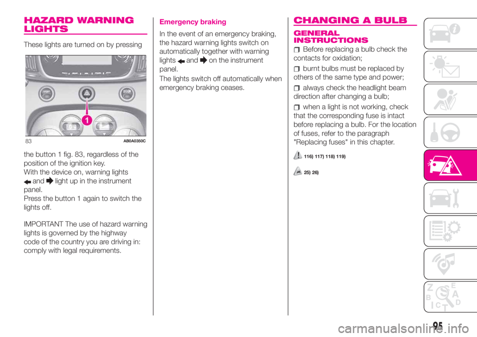
These lights are turned on by pressing
the button 1 fig. 83, regardless of the
position of the ignition key.
With the device on, warning lights
andlight up in the instrument
panel.
Press the button 1 again to switch the
lights off.
IMPORTANT The use of hazard warning
lights is governed by the highway
code of the country you are driving in:
comply with legal requirements.
Emergency braking
In the event of an emergency braking,
the hazard warning lights switch on
automatically together with warning
lights
andon the instrument
panel.
The lights switch off automatically when
emergency braking ceases.
CHANGING A BULB
GENERAL
INSTRUCTIONS
Before replacing a bulb check the
contacts for oxidation;
burnt bulbs must be replaced by
others of the same type and power;
always check the headlight beam
direction after changing a bulb;
when a light is not working, check
that the corresponding fuse is intact
before replacing a bulb. For the location
of fuses, refer to the paragraph
"Replacing fuses" in this chapter.
116) 117) 118) 119)
25) 26)
83AB0A0350C
95
Page 98 of 196
IMPORTANT When the weather is cold
or damp or after heavy rain or washing,
the surface of headlights or rear lights
may steam up and/or form drops of
condensation on the inside. This is
a natural phenomenon due to the
difference in temperature and humidity
between the inside and the outside
of the glass which does not indicate a
fault and does not compromise the
normal operation of lighting devices.
The mist disappears quickly when the
lights are turned on, starting from
the centre of the diffuser, extending
progressively towards the edges
96
IN AN EMERGENCY
Page 105 of 196
REPLACING FUSES
GENERAL INFORMATION
Fuses protect the electrical system:
they intervene (blow) in the event of a
failure or improper action on the
system.
121) 122) 123) 124) 125) 126)
To facilitate fuse replacement, use the
pliers hooked inside the fuse box lid on
the dashboard left-hand side.
Refer to the tables on the following
pages to identify the protective fuse.
FUSE LOCATION
Dashboard fuse box
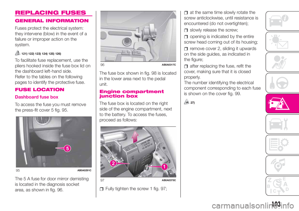
To access the fuse you must remove
the press-fit cover 5 fig. 95.
The 5 A fuse for door mirror demisting
is located in the diagnosis socket
area, as shown in fig. 96.The fuse box shown in fig. 98 is located
in the lower area next to the pedal
unit.
Engine compartment
junction box
The fuse box is located on the right
side of the engine compartment, next
to the battery. To access the fuses,
proceed as follows:
Fully tighten the screw 1 fig. 97;
at the same time slowly rotate the
screw anticlockwise, until resistance is
encountered (do not overtighten);
slowly release the screw;
opening is indicated by the entire
screw head coming out of its housing;
remove cover 2, sliding it upwards
on the side guides, as indicated in
the figure;
after replacing the fuse, refit the
cover, making sure that it is closed
properly.
The number identifying the electrical
component corresponding to each fuse
is shown on the cover fig. 99.
27)
95AB0A0291C
96AB0A0317C
97AB0A0375C
103
Page 106 of 196
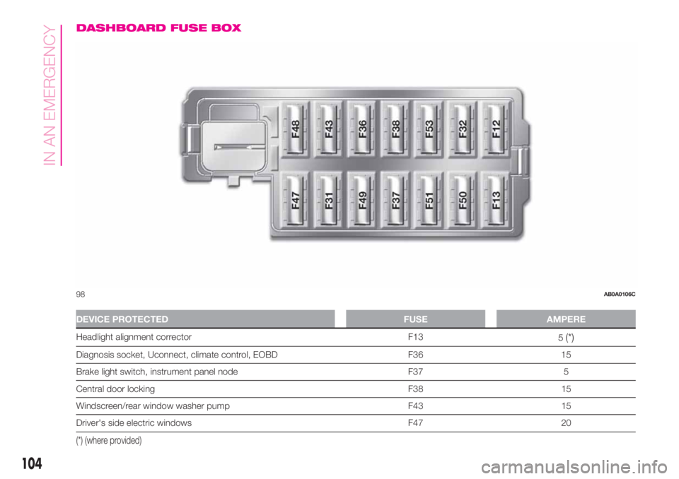
DASHBOARD FUSE BOX
DEVICE PROTECTED FUSE AMPERE
Headlight alignment corrector F13
5(*)
Diagnosis socket, Uconnect, climate control, EOBD F36 15
Brake light switch, instrument panel node F37 5
Central door locking F38 15
Windscreen/rear window washer pump F43 15
Driver's side electric windows F47 20
(*) (where provided)
98AB0A0106C
104
IN AN EMERGENCY
Page 107 of 196
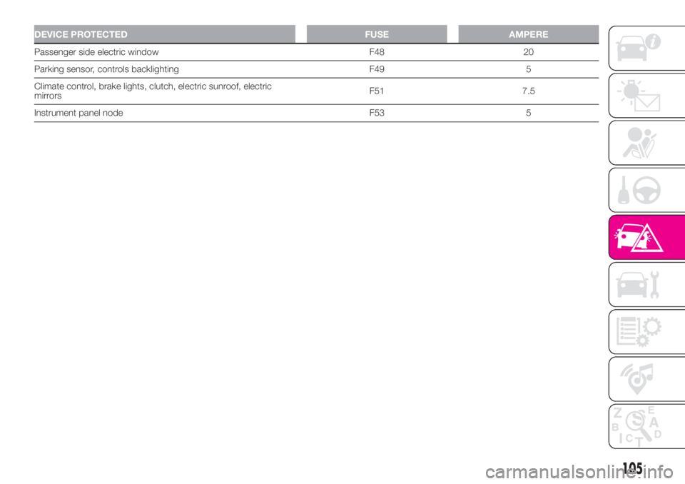
DEVICE PROTECTED FUSE AMPERE
Passenger side electric window F48 20
Parking sensor, controls backlighting F49 5
Climate control, brake lights, clutch, electric sunroof, electric
mirrorsF51 7.5
Instrument panel node F53 5
105