Abarth Grande Punto 2010 Owner handbook (in English)
Manufacturer: ABARTH, Model Year: 2010, Model line: Grande Punto, Model: Abarth Grande Punto 2010Pages: 207, PDF Size: 3.01 MB
Page 51 of 207

49
SAFETY
DEVICES
CORRECT USE
OF THE CAR
WARNING
LIGHTS AND
MESSAGES
IIN AN
EMERGENCY
CAR
MAINTENANCE
TECHNICAL
SPECIFICATIONS
INDEX
DASHBOARD
AND CONTROLS
WINDOW WASHING
The right stalk fig. 37controls windscreen
wiper/washer and heated rear window
wiper/washer operation.
WINDSCREEN WASHER/
WIPER
The device can only work when the igni-
tion key is atMAR.
The stalk ring nut can be moved to four
different positions:
Owindscreen wiper off;
≤intermittent;
≥continuous slow;
¥continuos fast.
Moving the stalk to A(unstable position)
operation is limited to the time the stalk
is held in this position. When the stalk is
released it returns to its original position
automatically stopping the wiper.Never use the window wiper
to remove ice or snow from
the windscreen. In these con-
ditions, the wiper is submitted
to excessive effort that results in motor
protection cutting in and wiper opera-
tion inhibition for few seconds as a con-
sequence. If operation is not restored
(also after restarting the car by the ig-
nition key) contact Abarth Dealership.
With ring nut at
≤, wiping speed is au-
tomatically adapted to the car speed.
IMPORTANT Replace wiper blades as
specified in section “Car maintenance”.
fig. 37F0M0062m
Page 52 of 207
50
SAFETY
DEVICES
CORRECT USE
OF THE CAR
WARNING
LIGHTS AND
MESSAGES
IN AN
EMERGENCY
CAR
MAINTENANCE
TECHNICAL
SPECIFICATIONS
INDEX
DASHBOARD
AND CONTROLS
RAIN SENSOR (for versions/
markets, where provided)
The rain sensor is located behind the dri-
ving mirror in contact with the windscreen
and has the purpose of automatically ad-
just, during the intermittent operation, the
frequency of the windscreen wiper
strokes as to the rain intensity.
IMPORTANT Keep clean the glass in the
sensor area.
Activation
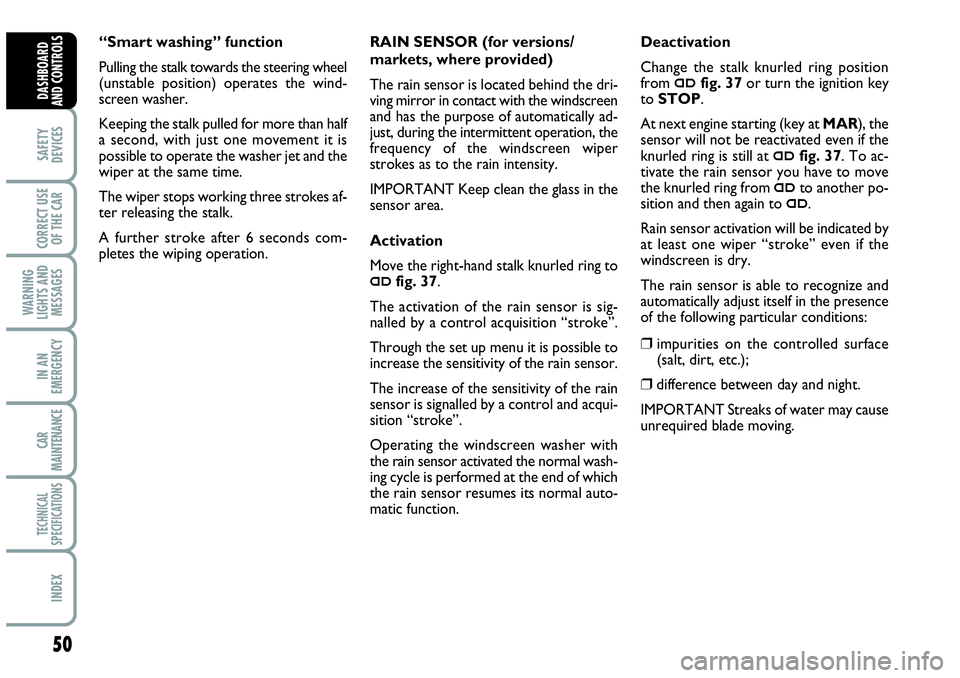
Move the right-hand stalk knurled ring to
≤fig. 37.
The activation of the rain sensor is sig-
nalled by a control acquisition “stroke”.
Through the set up menu it is possible to
increase the sensitivity of the rain sensor.
The increase of the sensitivity of the rain
sensor is signalled by a control and acqui-
sition “stroke”.
Operating the windscreen washer with
the rain sensor activated the normal wash-
ing cycle is performed at the end of which
the rain sensor resumes its normal auto-
matic function.Deactivation
Change the stalk knurled ring position
from
≤fig. 37or turn the ignition key
to STOP.
At next engine starting (key at MAR), the
sensor will not be reactivated even if the
knurled ring is still at
≤fig. 37. To ac-
tivate the rain sensor you have to move
the knurled ring from
≤to another po-
sition and then again to
≤.
Rain sensor activation will be indicated by
at least one wiper “stroke” even if the
windscreen is dry.
The rain sensor is able to recognize and
automatically adjust itself in the presence
of the following particular conditions:
❒ impurities on the controlled surface
(salt, dirt, etc.);
❒difference between day and night.
IMPORTANT Streaks of water may cause
unrequired blade moving. “Smart washing” function
Pulling the stalk towards the steering wheel
(unstable position) operates the wind-
screen washer.
Keeping the stalk pulled for more than half
a second, with just one movement it is
possible to operate the washer jet and the
wiper at the same time.
The wiper stops working three strokes af-
ter releasing the stalk.
A further stroke after 6 seconds com-
pletes the wiping operation.
Page 53 of 207

51
SAFETY
DEVICES
CORRECT USE
OF THE CAR
WARNING
LIGHTS AND
MESSAGES
IIN AN
EMERGENCY
CAR
MAINTENANCE
TECHNICAL
SPECIFICATIONS
INDEX
DASHBOARD
AND CONTROLS
REAR WINDOW WASHER/WIPER
fig. 38
The device can only work when the igni-
tion key is at MAR.
Operation will stop when releasing the
stalk.
Turning the knurled ring from Oto
'will
operate the rear window wiper as follows:
❒intermittent operation if the wind-
screen wiper is off;
❒synchronised with the windscreen
wiper (but with half stroke frequency);
❒continuous operation with reverse en-
gaged and windscreen wiper on.Never use the rear window
wiper to remove ice or snow
from the rear window. In these
conditions, the wiper is sub-
mitted to excessive effort that results in
motor protection cutting in and wiper
operation inhibition for few seconds as
a consequence. If operation is not re-
stored contact Abarth Dealership.
With windscreen wiper on and reverse
gear engaged, rear window wiping will be
continuous.
Pushing the stalk towards the dashboard
(unstable position) will activate the rear
window washer.
Keeping the stalk pushed for over half a
second will activate also the rear window
wiper.
Releasing the stalk will activate the smart
washing function as described for the
windscreen wiper.
fig. 38F0M0218m
Page 54 of 207

52
SAFETY
DEVICES
CORRECT USE
OF THE CAR
WARNING
LIGHTS AND
MESSAGES
IN AN
EMERGENCY
CAR
MAINTENANCE
TECHNICAL
SPECIFICATIONS
INDEX
DASHBOARD
AND CONTROLS
CRUISE CONTROL
(constant speed
regulator)
(for versions/markets,
where provided)
It is a device able to support the driver,
with electronic control, which allows dri-
ving at speed over 30 km/h on long and
straight dry roads (e.g.: motorways), at a
desired speed, without pressing the ac-
celerator pedal. Therefore it is not sug-
gested to use this device on extra-urban
roads with traffic. Do not use it in town.DEVICE ENGAGEMENT
Turn knob A-fig. 39to ON.
The Cruise Control cannot be engaged
in first or reverse gear. It is advisable to
engage it in 4th or higher gears.
Travelling downhill with the device en-
gaged, the car speed may increase more
than the memorised one.
When the device is activated the warn-
ing light
Üturns on together with the rel-
evant message on the instrument panel
(for versions/markets, where provided).TO MEMORISE SPEED
Proceed as follows:
❒turn knob A-fig. 39to ONand press
the accelerator pedal to the required
speed;
❒move the stalk upwards (+) for at
least one second, then release it. The
car speed is memorised and it is
therefore possible to release the ac-
celerator pedal.
In the case of need (when overtaking for
instance) acceleration is possible simply
pressing the accelerator pedal: releasing
the accelerator pedal, the car will return
to the speed memorised previously.
fig. 39F0M0064m
Page 55 of 207
53
SAFETY
DEVICES
CORRECT USE
OF THE CAR
WARNING
LIGHTS AND
MESSAGES
IIN AN
EMERGENCY
CAR
MAINTENANCE
TECHNICAL
SPECIFICATIONS
INDEX
DASHBOARD
AND CONTROLS
TO RESET THE
MEMORISED SPEED
If the device has been disengaged for ex-
ample pressing the brake or clutch pedal,
the memorised speed can be reset as fol-
lows:
❒accelerate gradually until reaching a
speed approaching the one memorised;
❒engage the gear selected at the time of
speed memorising;
❒press button RES B-fig. 39.
TO INCREASE THE
MEMORISED SPEED
The speed memorised can be increased in
two ways:
❒pressing the accelerator and then mem-
orising the new speed reached;
or
❒moving the stalk upwards (+).
Each operation of the stalk will corre-
spond to a slight increase in speed (about
1 km/h), while keeping the stalk upwards
will correspond to a continuous speed in-
crease. TO REDUCE
MEMORISED SPEED
The speed memorised can be increased in
two ways:
❒disengaging the device and then mem-
orising the new speed;
or
❒moving the stalk downwards (–) until
reaching the new speed which will be
memorised automatically.
Each operation of the stalk will corre-
spond to a slight reduction in speed (about
1 km/h), while keeping the stalk down-
wards will correspond to a continuous
speed reduction.
DEVICE DISENGAGEMENT
The device can be disengaged in the fol-
lowing ways:
❒turn knob Ato OFF;
❒turning the engine off;
❒pressing the brake pedal;
❒pressing the clutch pedal;
❒pressing the accelerator pedal; in this
case the system is not really disengaged
but the request for acceleration takes
priority over the system. The cruise
control is however active and it will not
be necessary to press button RES
B-fig. 39to resume previous condi-
tions after ending acceleration.
The device is automatically deactivated in
one of the following cases:
❒ABSor ESPsystem cut-in;
❒ with car speed below the preset limit;
❒system failure.
When travelling with the de-
vice on, never set the
gearshift lever to neutral.
WARNING
In the event of device mal-
function or failure, turn knob
A to OFF and contact a Abarth Deal-
ership.
WARNING
Page 56 of 207
54
SAFETY
DEVICES
CORRECT USE
OF THE CAR
WARNING
LIGHTS AND
MESSAGES
IN AN
EMERGENCY
CAR
MAINTENANCE
TECHNICAL
SPECIFICATIONS
INDEX
DASHBOARD
AND CONTROLS
CEILING LIGHTS
FRONT CEILING LIGHT WITH
SPOT LIGHTS
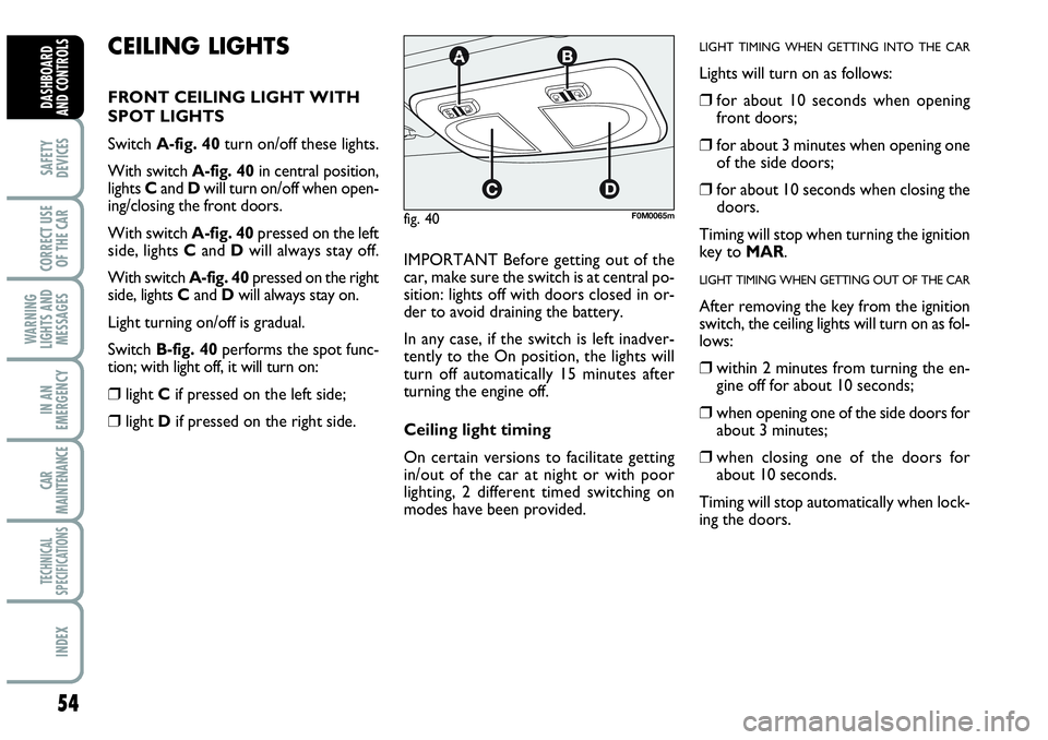
Switch A-fig. 40turn on/off these lights.
With switch A-fig. 40in central position,
lights Cand Dwill turn on/off when open-
ing/closing the front doors.
With switch A-fig. 40pressed on the left
side, lights Cand Dwill always stay off.
With switch A-fig. 40pressed on the right
side, lights Cand Dwill always stay on.
Light turning on/off is gradual.
Switch B-fig. 40performs the spot func-
tion; with light off, it will turn on:
❒light Cif pressed on the left side;
❒light Dif pressed on the right side.IMPORTANT Before getting out of the
car, make sure the switch is at central po-
sition: lights off with doors closed in or-
der to avoid draining the battery.
In any case, if the switch is left inadver-
tently to the On position, the lights will
turn off automatically 15 minutes after
turning the engine off.
Ceiling light timing
On certain versions to facilitate getting
in/out of the car at night or with poor
lighting, 2 different timed switching on
modes have been provided.
LIGHT TIMING WHEN GETTING INTO THE CAR
Lights will turn on as follows:
❒for about 10 seconds when opening
front doors;
❒for about 3 minutes when opening one
of the side doors;
❒for about 10 seconds when closing the
doors.
Timing will stop when turning the ignition
key to MAR.
LIGHT TIMING WHEN GETTING OUT OF THE CAR
After removing the key from the ignition
switch, the ceiling lights will turn on as fol-
lows:
❒within 2 minutes from turning the en-
gine off for about 10 seconds;
❒when opening one of the side doors for
about 3 minutes;
❒when closing one of the doors for
about 10 seconds.
Timing will stop automatically when lock-
ing the doors.
fig. 40F0M0065m
Page 57 of 207

55
SAFETY
DEVICES
CORRECT USE
OF THE CAR
WARNING
LIGHTS AND
MESSAGES
IIN AN
EMERGENCY
CAR
MAINTENANCE
TECHNICAL
SPECIFICATIONS
INDEX
DASHBOARD
AND CONTROLS
BOOT LIGHT fig. 41
For versions fitted with boot light, it will
turn on automatically when opening the
tailgate and it will turn off at closing.
PUDDLE LIGHTS fig. 42
These lights Aare located in the doors
and they will turn on when opening the
relevant door, regardless of the ignition
key position.
CONTROLS
HAZARD LIGHTS fig. 43
They turn on by pressing switch A, re-
gardless of the position of the ignition key.
When the device is on warning lights
Îand ¥on the cluster come on.
Press the switch again to turn the lights
off.
The use of hazard lights is governed by the
Highway Code of the country you are in.
Keep to the rules.
FRONT FOG LIGHTS fig. 44
To active, with front side lights on, press
button
5.
Warning light
5on the instrument pan-
el will turn on.
Press the button again to turn the lights
off.
The use of front fog lights is governed by
the Highway Code of the country you are
in. Keep to the rules.
fig. 41F0M0068m
fig. 42F0M0176m
fig. 43F0M073Ab
fig. 44F0M0070m
Page 58 of 207

56
SAFETY
DEVICES
CORRECT USE
OF THE CAR
WARNING
LIGHTS AND
MESSAGES
IN AN
EMERGENCY
CAR
MAINTENANCE
TECHNICAL
SPECIFICATIONS
INDEX
DASHBOARD
AND CONTROLS
HEATED REAR WINDOW fig. 47
Press button Ato turn on this function.
This function will turn off automatically af-
ter about 20 minutes. REAR FOG LIGHT fig. 45
Press button 4, to turn these lights on it
is necessary to have the dipped beam head-
lights or the front fog lights (for versions/
markets, where provided) switched on.
Warning light 4on the instrument panel
will turn on.
Press the button again to turn the light off
or turn off dipped beams and/or front fog
lights (for versions/markets, where pro-
vided).
The use of rear fog lights is governed by the
Highway Code of the country you are in.
Keep to the rules.
PARKING LIGHTS
These lights can only be turned on with ig-
nition key at STOP or removed, by mov-
ing the left stalk knurled ring first to Oand
then to
6or 2.
The warning light
3on the instrument
cluster will come on at the same time.SPORT BOOST fig. 46
Press the Abutton to start the “SPORT
BOOST” function (see “SPORT BOO-
ST” paragraph in the herein section). On-
ce this function has been started, the
“SPORT” warning light on the instru-
ment board panel turns on. Press the A
button again to switch this function off.
fig. 45F0M0071mfig. 47F0M0038mfig. 46F0M074Ab
Page 59 of 207
57
SAFETY
DEVICES
CORRECT USE
OF THE CAR
WARNING
LIGHTS AND
MESSAGES
IIN AN
EMERGENCY
CAR
MAINTENANCE
TECHNICAL
SPECIFICATIONS
INDEX
DASHBOARD
AND CONTROLS
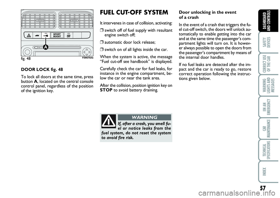
DOOR LOCK fig. 48
To lock all doors at the same time, press
button A, located on the central console
control panel, regardless of the position
of the ignition key.
FUEL CUT-OFF SYSTEM
It intervenes in case of collision, activating:
❒switch off of fuel supply with resultant
engine switch off;
❒automatic door lock release;
❒switch on of all lights inside the car.
When the system is active, the message
“Fuel cut-off see handbook” is displayed.
Carefully check the car for fuel leaks, for
instance in the engine compartment, be-
low the car or near the tank area.
After the collision, position ignition key on
STOPto avoid battery draining.
fig. 48F0M076Ab
Door unlocking in the event
of a crash
In the event of a crash that triggers the fu-
el cut-off switch, the doors will unlock au-
tomatically to enable getting into the car
and at the same time the passenger’s com-
partment lights will turn on. It is howev-
er always possible to open the doors from
the passenger’s compartment by means of
the internal door handles.
If no fuel leaks are detected after the im-
pact and the car is ready to go, restore
correct operation following the instruc-
tions given below.
If, after a crash, you smell fu-
el or notice leaks from the
fuel system, do not reset the system
to avoid fire risk.
WARNING
Page 60 of 207
58
SAFETY
DEVICES
CORRECT USE
OF THE CAR
WARNING
LIGHTS AND
MESSAGES
IN AN
EMERGENCY
CAR
MAINTENANCE
TECHNICAL
SPECIFICATIONS
INDEX
DASHBOARD
AND CONTROLS
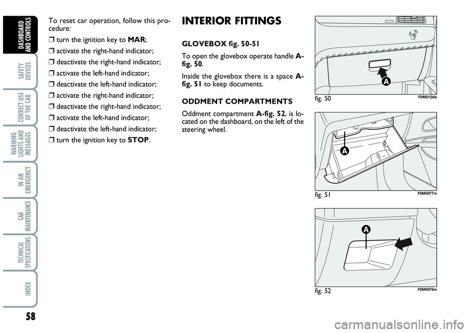
INTERIOR FITTINGS
GLOVEBOX fig. 50-51
To open the glovebox operate handle A-
fig. 50.
Inside the glovebox there is a space A-
fig. 51to keep documents.
ODDMENT COMPARTMENTS
Oddment compartment A-fig. 52, is lo-
cated on the dashboard, on the left of the
steering wheel.
fig. 51F0M0077m
fig. 50F0M012Ab
fig. 52F0M0078m
To reset car operation, follow this pro-
cedure:
❒turn the ignition key to MAR;
❒activate the right-hand indicator;
❒deactivate the right-hand indicator;
❒activate the left-hand indicator;
❒deactivate the left-hand indicator;
❒activate the right-hand indicator;
❒deactivate the right-hand indicator;
❒activate the left-hand indicator;
❒deactivate the left-hand indicator;
❒turn the ignition key to STOP.